manuals.online logo
Brands
  1. Home
  2. •
  3. Brands
  4. •
  5. Tekon
  6. •
  7. Microphone System
  8. •
  9. Tekon DUOS User manual

Tekon DUOS User manual

TEKON ELECTRONICS AVEIRO, PORTUGAL
P.: +351 234 303 320 M.: +351 933 033 250 E.: sales@tekonelectronics.com
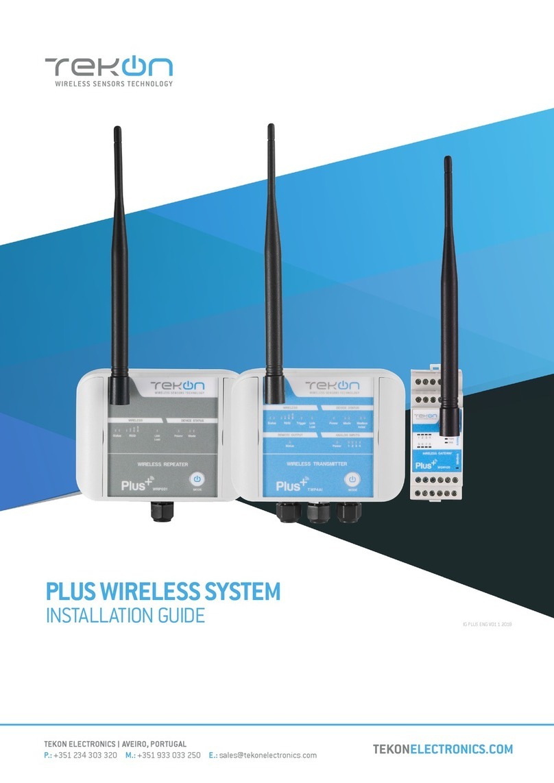
DUOS WIRELESS SYSTEM
INSTALLATION GUIDE
TEKON ELECTRONICS AVEIRO, PORTUGAL
P.: +351 234 303 320 M.: +351 933 033 250 E.: sales@tekonelectronics.com
IG.DUOS.ENG.V01.3.2018
2
DUOS WIRELESS SYSTEM INSTALLATION GUIDE
01
step
02
step
CONNECT AND CONFIGURE THE DUOS WIRELESS GATEWAY
Pages 4 to 10
CONNECT AND CONFIGURE THE DUOS WIRELESS TRANSMITTER
Pages 11 to 15
DUOS WIRELESS SYSTEM
INSTALLATION GUIDE
Table of contents
3
DUOS WIRELESS SYSTEM INSTALLATION GUIDE
03
step
04
step
CHECK WIRELESS COMMUNICATION BETWEEN THE DUOS TRANSMITTER AND THE GATEWAY
Page 16
CONNECT AND CONFIGURE THE DUOS WIRELESS REPEATER
Pages 17 to 22
DUOS WIRELESS SYSTEM
INSTALLATION GUIDE
Table of contents
4
DUOS WIRELESS SYSTEM INSTALLATION GUIDE
01
step
CONNECT AND CONFIGURE THE DUOS WIRELESS GATEWAY
01 Connect the antenna to the Gateway.
02 Connect the DUOS RS485-USB cable to the
computer and then to the Gateway.
03 Check the device connection through the LED signage.
If the red and blue LEDs are active, both the cable and Gateway are working correctly.
LED ashes slowly
LED switched on and steady
Red LED ashes every second
whenever it sends beacons to new
elements to join the network
Green LED ashes as soon as the
device receives data from other
equipment
10 Seconds to enter
conguration mode
TEKON CONFIGURATOR SOFTWARE is only compatible with the Microsoft Windows Operating System.
01
step
CONNECT AND CONFIGURE THE DUOS WIRELESS GATEWAY
5
DUOS WIRELESS SYSTEM INSTALLATION GUIDE
04 Open Tekon Congurator Software1and select from the menu DUOS >> Gateway >> Conguration
05 Select the Serial Port of the DUOS Wireless Gateway
Click on the Refresh Serial Ports button.
2
1
3
1 Tekon Congurator software is free of charge and available at www.tekonelectronics.com
6
DUOS WIRELESS SYSTEM INSTALLATION GUIDE
01
step
CONNECT AND CONFIGURE THE DUOS WIRELESS GATEWAY
06 Select the Port name2of the device.
07 Remove the DUOS RS485-USB cable from the
Gateway side and reinsert it.
NOTE:
After reinserting the cable, you have 10 seconds to enter in conguration mode by clicking on the Connect ( )
button, while the blue LED ashes slowly.
In this mode, you can manage the device parameters: Modbus Address, Modbus baud rate, Modbus Parity, Wire-
less Network ID and Wireless Channel.
2You can check the device port name in the Device Manager menu in the Windows operating system.
01
step
CONNECT AND CONFIGURE THE DUOS WIRELESS GATEWAY
7
DUOS WIRELESS SYSTEM INSTALLATION GUIDE
08
10 Seconds to enter
conguration mode
LED ashes slowly
LED ashes quickly
LED switched on and steady
Click on the Connect ( ) button to enter conguration mode.
The status string at the bottom of the software window gives feedback of reading operations, as well as the
Gateway LED indication.
NOTE:
When 10 seconds have been exceeded, the blue LED is steady and it is no longer possible to enter conguration
mode. In this case, the cable must be removed and reiserted - step 2.
8
DUOS WIRELESS SYSTEM INSTALLATION GUIDE
01
step
CONNECT AND CONFIGURE THE DUOS WIRELESS GATEWAY
09
10 Click on the Disconnect ( ) button.
The Modbus interface and the wireless network are active if the blue LED is on and steady and the red LED is ashing
once per second.
Take note of the device conguration data available, namely: Modbus Address, Modbus Baudrate, Modbus Parity,
Wireless Network ID and Wireless Channel.
NOTE:
The wireless network connection between devices is ensured by the Wireless Network ID and Wireless Channel
eld parameters.
01
step
CONNECT AND CONFIGURE THE DUOS WIRELESS GATEWAY
9
DUOS WIRELESS SYSTEM INSTALLATION GUIDE
11 Modbus Communication
Open the Modbus tab of the Gateway and set the previously saved congurations.
Ensure that the Port name, Baudrate, Parity and the Modbus Address elds are the same obtained in conguration mode.
LED switched on and steady
Red LED ashes every second
whenever it sends beacons
to new elements to join the
network.
10
DUOS WIRELESS SYSTEM INSTALLATION GUIDE
01
step
CONNECT AND CONFIGURE THE DUOS WIRELESS GATEWAY
12
The messages Connected to Modbus and Reading successfully will appear if the Serial Port conguration
parameters are correct and the Modbus connection established.
If the blue LED is on and steady and red LED ashes once per second, the Gateway is fully operational on the
Modbus and wireless interfaces.
Click on the Connect ( ) button and check the operation status at the bottom of the window.
02
step
CONNECT AND CONFIGURE THE DUOS WIRELESS TRANSMITTER
DUOS WIRELESS SYSTEM INSTALLATION GUIDE
11
01 Connect probe to the DUOS Wireless
Transmitter.
The DUOS Temp Wireless Transmitter is the
device chosen for this guide.
The following steps are valid for any Transmitter from the DUOS system.
The device (previously mentioned as “unknown model”), as well as the rmware and hardware versions, will be detected when
the USB is set. The Tekon Congurator software graphical interface is then adjusted to the detected device.
NOTE:
Although the transmitters are physically equal, probe compatibility is different. This means that the DUOS TEMP
Wireless Transmitter is only compatible with temperature probes (models: Plug and Play probe and Temperature
Probe), whereas the DUOS Hygrotemp Wireless Transmitter is only compatible with temperature and humidity
probes (models: TK07-PFT5 and TK07-MFT9-HC01).
02 Open a new window of the Tekon Congurator Software and select the menu DUOS >> Transmitter.
2
1
12
DUOS WIRELESS SYSTEM INSTALLATION GUIDE
02
step
CONNECT AND CONFIGURE THE DUOS WIRELESS TRANSMITTER
03 Connect the DUOS TRANSMITTER SARC cable
to the computer and then to the transmitter.
After cable connection, all LEDs stay active
during 10 seconds.
LED switched on and steady
04 Click on the Refresh Serial Ports button.
02
step
CONNECT AND CONFIGURE THE DUOS WIRELESS TRANSMITTER
DUOS WIRELESS SYSTEM INSTALLATION GUIDE
13
05 Select the Port name of the device. 3
3You can check the device port name in the Device Manager menu in the Windows operating system.
06 Remove the cable from the Transmitter side
and reinsert it. This will access the device’s
conguration input window during 10
seconds.
14
DUOS WIRELESS SYSTEM INSTALLATION GUIDE
02
step
CONNECT AND CONFIGURE THE DUOS WIRELESS TRANSMITTER
Click on Connect ( ) button to enter conguration mode. These congurations are read automatically.
In conguration mode, the Transmitter activates 4 LEDS: 2 blue LEDs ash and the red and green LEDs remain
active and steady.
LED ashes quickly
LED stays on and xed
NOTE:
After reinserting the cable, you have 10 seconds to enter conguration mode by clicking on the Connect ( )
button, while the blue LEDs ash slowly.
When the 10 seconds have been exceeded, the blue LEDs are steady and it is no longer possible to enter
conguration mode.
In that case, the cable must be removed from the Transmitter and reiserted - step 3.
07 The status string at the bottom of the software window gives feedback on reading operations.
The device’s identication data is now available in the software window.
In this guide, the DUOS TEMP Wireless Transmitter has been considered.
02
step
CONNECT AND CONFIGURE THE DUOS WIRELESS TRANSMITTER
DUOS WIRELESS SYSTEM INSTALLATION GUIDE
15
08 Congure the Wireless Network ID and the Wireless Channel previously obtained from the Gateway. The wireless
connection between both devices is ensured by the Wireless Network ID and the Wireless Channel parameters.
Ensure that the Transmitter ID is unique in the network. Each device must have a different Transmitter ID. Change
it (if necessary) and take note to view the data later.
Click on the Write button to update the settings for the Transmitter.
16
DUOS WIRELESS SYSTEM INSTALLATION GUIDE
02
step
CONNECT AND CONFIGURE THE DUOS WIRELESS TRANSMITTER
09 Click on the Conguration Mode ( ) button to exit setup and start the equipment in normal operation mode.
After this procedure:
• The Transmitter awaits connection to the Gateway, when only the red LED ashes;
LED ashes slowly
• The Transmitter is connected via wireless and its data is available in the Gateway, when the red and green
LEDs ash.
LED ashes
NOTE:
If the green LED does not ash, communication as not been established. Make sure that the devices are at a distance of
at least 3 meters, or remove the antenna from the gateway (in case both devices are near each other).
The Transmitter LEDs remain active during 1 minute. After this period, all LEDs shut down in order to optimise battery life.
To reset the transmitter, the batteries should be removed, during - at least - 50 seconds (in sleep mode) or instead, as the
transmitter has a magnetic switch, a magnet can be used to reset it by passing the magnet close to the transmitter’s front
side in the blue LED’s area.
03
step
CHECK WIRELESS COMMUNICATION BETWEEN THE DUOS TRANSMITTER AND THE GATEWAY
DUOS WIRELESS SYSTEM INSTALLATION GUIDE
17
01
02
Place the two windows of Tekon Congurator software devices’ side by side, in order to analyse communication
between both devices.
Select the congured Transmitter ID in the Gateway window. After this, it is possible to access the address
window of the Transmitter in analysis.
The communication between devices is successfull when the Communication Period eld is in compliance with
its duration cycle. Therefore, as soon as the cycle duration has nished, it will turn back to 0.
Communication does not occur if the Communication Period eld presents a higher value than the Elapsed Time
eld.
In the following example, it was established that the temperature monitoring cycle (or Elapsed Time) is 2 seconds.
Therefore, the Communication Period eld will turn back to 0 as soon as it reaches 2 seconds and the analysed
parameters (in this case, the temperature) will be updated in accordance with ambient conditions.
You can dene the communication period of the Transmitter (or the Elapsed Time) in the write eld by clicking on
the register ( ) button.
DUOS WIRELESS SYSTEM INSTALLATION GUIDE
04
step
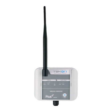
CONNECT AND CONFIGURE THE DUOS WIRELESS REPEATER
18
01 Connect the antenna to the Repeater.
02 Connect the DUOS RS485-USB cable to the
computer and then to Repeater.
Check the device connection through the LEDs signage.
LED switched on and steady
(red/green LED)
LED switched off
POWER ON
When connected
to the Gateway
04
step
CONNECT AND CONFIGURE THE DUOS WIRELESS REPEATER
DUOS WIRELESS SYSTEM INSTALLATION GUIDE
19
03 Open the Tekon Congurator Software and select the menu DUOS >> Repeater.
04 Click on Refresh Serial Ports button.
DUOS WIRELESS SYSTEM INSTALLATION GUIDE
04
step
CONNECT AND CONFIGURE THE DUOS WIRELESS REPEATER
20
05 Select Port name of the device.4
4You can check the device port name in the Device Manager menu in the Windows operating system.
06 Remove the cable from Repeater and reinsert it.
After reinserting the cable you have 10
seconds to enter conguration mode
by clicking on the Connect ( ) button,
while the blue LED ashes slowly.erting
the cable you have 10 seconds to enter in
conguration mode by clicking on Connect
button, while blue LED ashes slowly.
NOTE:
When the 10 seconds have been exceeded, the blue LED remains steady and it is no longer possible to enter
Conguration mode. In that case, the cable must be removed from Repeater and reiserted.

Other Tekon Microphone System manuals

Tekon Plus Series User manual

Tekon

Tekon Plus Series User manual

Tekon PLUS TWPH-1UT User manual

Tekon

Tekon PLUS TWPH-1UT User manual

Tekon PLUS TWP4AI User manual

Tekon

Tekon PLUS TWP4AI User manual

Tekon PLUS TWP4AI User manual

Tekon

Tekon PLUS TWP4AI User manual

Popular Microphone System manuals by other brands

Majorcom: EMAGP16 user manual

Majorcom:

Majorcom: EMAGP16 user manual

ETC CS-64-F Administration & setup guide

ETC

ETC CS-64-F Administration & setup guide

Sennheiser Evolution Wireless Digital EW-DX EM 2 quick guide

Sennheiser

Sennheiser Evolution Wireless Digital EW-DX EM 2 quick guide

AkkuPoint TPH 900 user manual

AkkuPoint

AkkuPoint TPH 900 user manual

4EVAC 4E-FM Installation and user guide

4EVAC

4EVAC 4E-FM Installation and user guide

Better Music Builder VM-62U Beta operating instructions

Better Music Builder

Better Music Builder VM-62U Beta operating instructions

Zycoo M100 Quick installation guide

Zycoo

Zycoo M100 Quick installation guide

Omnitronic UHF-502 user manual

Omnitronic

Omnitronic UHF-502 user manual

VocoPro UHF-5900 owner's manual

VocoPro

VocoPro UHF-5900 owner's manual

JTS R-4 instruction manual

JTS

JTS R-4 instruction manual

Shure UHF Wireless System user guide

Shure

Shure UHF Wireless System user guide

Toa WA-641C Specifications

Toa

Toa WA-641C Specifications

Stagg SUW50 user manual

Stagg

Stagg SUW50 user manual

Gemini UHF UX-1600 instruction manual

Gemini

Gemini UHF UX-1600 instruction manual

VocoPro UHF-5805 owner's manual

VocoPro

VocoPro UHF-5805 owner's manual

Voscom VOS-0100FT/R Series installation manual

Voscom

Voscom VOS-0100FT/R Series installation manual

Shure T series user guide

Shure

Shure T series user guide

Otto Earphone Kit user manual

Otto

Otto Earphone Kit user manual

manuals.online logo
manuals.online logoBrands
  • About & Mission
  • Contact us
  • Privacy Policy
  • Terms and Conditions

Copyright 2025 Manuals.Online. All Rights Reserved.