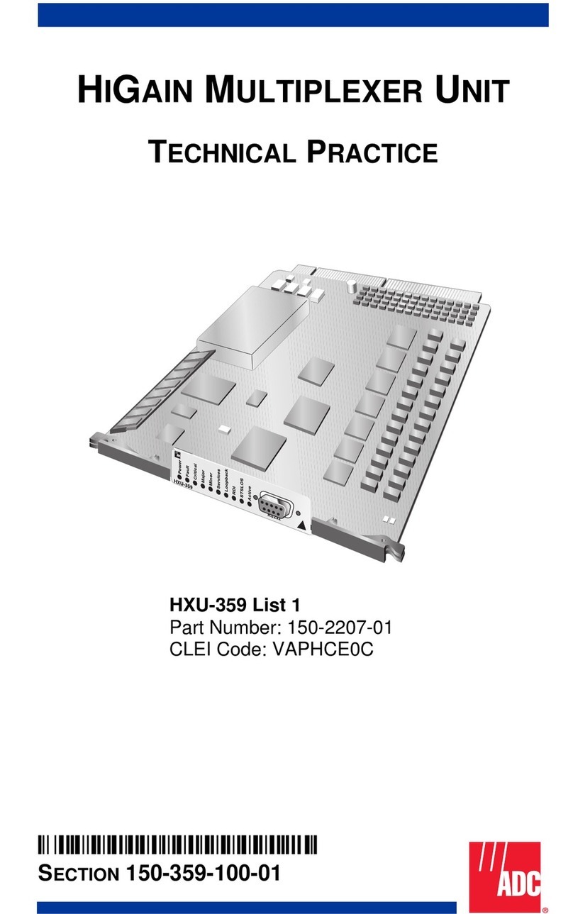
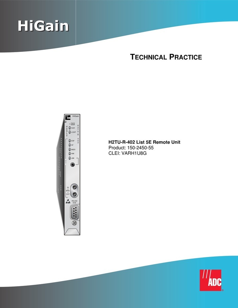
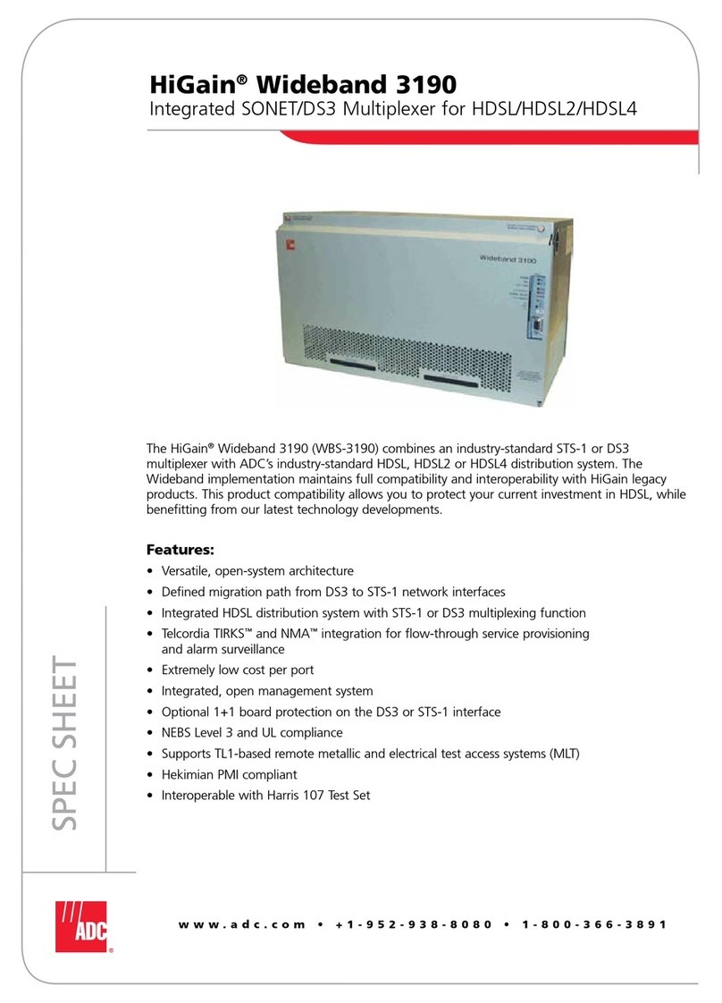
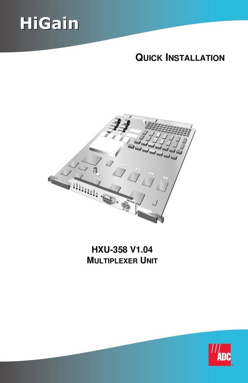
ADC HiGain HXU-357 User manual

HiGain
HiGain
USER MANUAL
HXU-357 List 1 HiGain Multiplexer Unit
Product Catalog: 150-2206-01
CLEI: T3D1JP0EAA

150-357-200-02, Issue 2
ii February 9, 1999 HXU-357 List 1
Revision History of This Manual
Copyright
February 9, 1999
© 1999 ADC DSL Systems, Inc. All rights reserved.
Trademark Information
ADC is a registered trademark of ADC Telecommunications, Inc. HiGain is a
registered trademark of ADC DSL Systems, Inc. No right, license, or interest to such
trademarks is granted hereunder, and you agree that no such right, license, or interest
shall be asserted by you with respect to such trademark.
Other product names mentioned in this practice are used for identification purposes
only and may be trademarks or registered trademarks of their respective companies.
Disclaimer of Liability
Information contained in this document is company private to ADC DSL Systems, Inc.,
and shall not be modified, used, copied, reproduced or disclosed in whole or in part
without the written consent of ADC.
Contents herein are current as of the date of publication. ADC reserves the right to
change the contents without prior notice. In no event shall ADC be liable for any
damages resulting from loss of data, loss of use, or loss of profits, and ADC further
disclaims any and all liability for indirect, incidental, special, consequential or other
similar damages. This disclaimer of liability applies to all products, publications and
services during and after the warranty period.
Revision Release Date Revisions Made
01 February 9, 1999 Initial Release
02 March 8, 2002 ADC rebranding

150-357-200-02, Issue 2 Using This Manual
HXU-357 List 1 February 9, 1999 iii
USING THIS MANUAL
The following conventions are used in this manual:
•Monospace type indicates screen text, including text you type at a
screen prompt.
•Keys you press are indicated by small icons such as . Key
combinations to be pressed simultaneously are indicated with a plus sign
as follows: + .
•Two types of messages, identified by icons, appear in text.
For a list of abbreviations used in this document, refer to “Appendix D -
Glossary”onpage63.
RELATED DOCUMENTATION
Notes contain information about special circumstances.
Cautions indicate the possibility of equipment damage,
potential loss of customer data or service, or the possibility
of personal injury.
Document Number Title
400-100-100-xx TL1 Command Set Reference
800-357-100-xx HMS-357 List 1 HiGain Wideband 3190
150-357-100-xx HFA-357 List 1 HiGain Fan Assembly
150-319-107-xx HMU-319 List 7 and 7A HiGain Management Unit
ENTER
CTRL ESC

Inspecting Shipment 150-357-200-02, Issue 2
iv February 9, 1999 HXU-357 List 1
INSPECTING SHIPMENT
Upon receipt of the equipment:
•Unpack each container and inspect the contents for signs of damage. If
the equipment has been damagedin transit, immediately report the extent
of damageto the transportation companyand to ADC DSL Systems, Inc.
Order replacement equipment, if necessary.
•Check the packing list to ensurecomplete and accurate shipment of each
listed item. If the shipment is short or irregular, contact ADC DSL
Systems, Inc. as described in “Appendix C - Product Support” on page
60. If you must store the equipment for a prolonged period, store the
equipment in its original container.

150-357-200-02, Issue 2 Table of Contents
HXU-357 List 1 February 9, 1999 v
TABLE OF CONTENTS
Overview _______________________________________________ 1
Features.................................................................................... 2
Application...............................................................................3
Description...............................................................................4
Functional Overview ................................................. 5
LED Indicators .......................................................... 6
Alarm Drivers............................................................ 7
Interfaces ................................................................... 8
Microprocessor.......................................................... 9
Microprocessor System Software.............................. 9
Multiplexer / Demultiplexer Circuitry..................... 10
Memory ................................................................... 10
Clock Circuit ........................................................... 10
Watchdog Timer...................................................... 11
Real Time Clock...................................................... 11
DC-to-DC Converter............................................... 11
Installation ____________________________________________ 12
Unpacking.............................................................................. 12
Safety Precautions.................................................................. 12
Installing the HXU-357.......................................................... 13
Provisioning ___________________________________________ 15
Accessing the Management Interface.................................... 15
Accessing the HXU-357 Root Menu..................................... 16
Minimal Configuration Requirements................................... 29
Setting up the Communications Channel to the HXU-357.... 31
Setting up System Administration......................................... 32

Table of Contents 150-357-200-02, Issue 2
vi February 9, 1999 HXU-357 List 1
Configuring the HXU DS3 Interface......................................33
Configuring the HXU DS1 Interface......................................34
Placing the Wideband 3190 in Service...................................35
Placing the HXU DS1 Interface in Service..............35
Placing the HXU DS3 Interface in Service..............36
HXU-357 Interface State Descriptions....................37
Understanding HXU-357 Alarms...........................................38
Viewing Alarm Status..............................................39
Alarm Lockout.........................................................43
Viewing System Configuration Status ...................................44
Viewing Performance at the HXU ........................................45
Upgrading the Multiplexer Software......................................46
Accessing the System Administration Screen .........47
Verifying the Multiplexer IP Address......................47
Setting the Download Filename...............................48
Setting the Server IP Address ..................................48
Beginning the Software Download..........................48
Burning in the Flash RAM.......................................48
Restoring Factory Defaults.....................................................49
Troubleshooting_________________________________________52
Appendix A - HXU-357 Specifications_______________________55
Appendix B - Network Addresses___________________________56
Hardware Addresses and IP Addresses....................56
Subnet Mask.............................................................57
Routers or Gateways................................................58
Trap IP Address .......................................................59

List of Figures 150-357-200-02, Issue 2
viii February 9, 1999 HXU-357 List 1
LIST OF FIGURES
1. HXU-357 Multiplexers Installed in Wideband 3190.............................1
2. HiGain Wideband 3190 Application .....................................................3
3. HXU-357 Multiplexer Block Diagram..................................................4
4. LED Indicators.......................................................................................6
5. Installing an HXU-357 Multiplexer Card............................................13
6. Management Interface .........................................................................16
7. Root Menu ...........................................................................................17
8. Root Menu for Multiplexer Configuration ..........................................19
9. System Loopbacks and Test Access....................................................52
10. Location of Bar Code Label and Configuration Number....................61

150-357-200-02, Issue 2 List of Tables
HXU-357 List 1 February 9, 1999 ix
LIST OF TABLES
1. HXU-357 LED Indicators..................................................................... 7
2. Keyboard Commands.......................................................................... 18
3. Configuration Management................................................................. 20
4. Performance Management................................................................... 23
5. Fault Management............................................................................... 24
6. System Configuration Status............................................................... 25
7. System Administration........................................................................ 26
8. DS3 Interface State Descriptions ........................................................ 37
9. DS1 Interface State Descriptions ........................................................ 38
10. HXU-357 Alarms................................................................................ 40
11. HXU-357 Default Software Settings................................................... 50
12. System Loopback Definitions ............................................................ 52
13. Network Addressing............................................................................ 57
14. Sample Class C IP Address Plan for the HMS-357 ............................ 58
15. Bar Code and Configuration Number ................................................. 62

List of Tables 150-357-200-02, Issue 2
x February 9, 1999 HXU-357 List 1

150-357-200-02, Issue 2 Overview
HXU-357 List 1 February 9, 1999 1
OVERVIEW
The HiGain®Multiplexer Unit HXU-357 List 1 is the newest generation of
broadband multiplexers. It offers a low-cost multiplexing solution that
features low-power consumption and a data transfer rate of 45 mbps. The
HXU-357 is designed for HiGain Wideband 3190s that provide a complete
T1 delivery system using a standard open architecture system in a 23-inch
rack space. These HiGain systems multiplex DS1 channels into a single,
industry-standard DS3 data channel. The HXU-357 is capable of transmitting
and receiving up to 28 DS1 signals over a DS3 interface. It also displays
standard office alarms (Figure 1).
When used in a protection configuration comprised of two multiplexers (one
active and the other as a standby), each card monitors the integrity of the user
data and automatically switches out a faulty unit.
Figure 1. HXU-357 Multiplexers Installed in Wideband 3190
PairGain
LB (loopback)
FAULT
ABNORMAL
Active multiplexer Standby multiplexer
ACTIVE
PWR (power)
FE (far end alarm)
MN (minor alarm)
MJ (major alarm)
CR (critical alarm)

Overview 150-357-200-02, Issue 2
2 February 9, 1999 HXU-357 List 1
FEATURES
•complete software provisioning
•advanced management using Terminal Access Option (TAO) or
Transaction Language 1 (TL1) software (through an HMU-319 List 7 or
List 7A)
•software-selectable DS3 local and network loopback
•DS1 line code and loopback options
•downloadable software
•automatic and manual protection switching
•password protection
•internal diagnostics testing
•office alarms (Major, Minor, Far-End, Critical)
•front panel status indicators

150-357-200-02, Issue 2 Overview
HXU-357 List 1 February 9, 1999 3
APPLICATION
The HXU-357 allows you to combine 28 lines into one high-speed DS3
interface, thus providing a substantial cost savings over 28 individual HDSL
lines.
Figure 2. HiGain Wideband 3190 Application

Overview 150-357-200-02, Issue 2
4 February 9, 1999 HXU-357 List 1
DESCRIPTION
This section provides a general functional overview and describes the key
components of the HXU-357 multiplexer.
Figure 3. HXU-357 Multiplexer Block Diagram
CH 1-28 RX
TIP and
RING
CH 1-28 RX
TIP and
RING
DS3 RX
DATA DS3 TX
LINE
DATA
DS3 RX
LINE
DATA
DS3
RX CLK
DS3 TX
DATA
DS3 TX
CLK
CH 1-28 TX
TIP and
RING
CH 1-28
TX DATA
CH 1-28
RX DATA
M13 MUX/DEMUX
DS1 Interface
CH 1-28
TX CLK
CH 1-28
RX CLK
CH 1-28 TX
TIP and
RING
28 DS1
LINE PROT
and
ON/OFF
LINE
DS3
MUX/
DEMUX
28 DS1
LIU DS3 LINE
TRANSCEIVER
MICROPROCESSOR
MC68EN302
I/O
SRAM
WATCH
DOG
REAL TIME
CLOCK
CRAFT TERMINAL
INTERFACE
ETHERNET
INTERFACE
INTER
MIC COM
CLOCK
CIRCUITRY
FLASHI/OEEPROM
DATA BUS
ADDRESS
BUS

150-357-200-02, Issue 2 Overview
HXU-357 List 1 February 9, 1999 5
Functional Overview
Transmit Signal Flow
In the transmit direction, the HXU-357 takes the 28 incoming bipolar,
asynchronous, Tl low-speed signals, and adds line conditioning. It then
multiplexes the signals with DS3 overhead data and stuffing bits to produce
an industry-standard DS3 data stream.
The DS3 data and timing signals are converted into a signal for coaxial
interface to external equipment. In a 1:1 protection configuration, the
microprocessor on each card monitors the integrity of the transmit data signal
from the active (primary) and standby card and communicates with the other
to determine the online card.
Receive Signal Flow
In the receive direction, the HXU-357 converts the incoming DS3 signal into
clock and data signals for interface to the demultiplexer circuitry. In a 1:1
protection configuration, the microprocessor on each card monitors the
integrity of the receive data signal and communicates with the other to
determine the online card.
The demultiplexer circuitry receives the DS3 data and timing signals and
demultiplexes them into the 28 DS1 signals. All stuffing bits added for bit
synchronization at the transmitting end of the system are deleted from the
data stream prior to line signal encoding.
Protection Switching
In a 1:1 protected configuration, the primary card is defined as the active or
online card. The secondary card is the standby. The microprocessors on each
card communicate with each other to determine active and standby status.
When a card fails, either because the external watch dog timer timed-out or
because the software detected a failure of the hardware, a priority switch is
initiated. If the failure is on the primary card, a priority switch to the
secondary card occurs. Priority switching occurs from the secondary card to
the primary card and, if necessary, back again until the fault is corrected or
more than three switches occur in a 10-minute period.

150-357-200-02, Issue 2 Overview
HXU-357 List 1 February 9, 1999 7
Alarm Drivers
The microprocessor drives the alarm relays for the multiplexer unit. The relay
outputs are wire-ORed from both cards on the back left side of the Wideband
System 3190 chassis and are read by the HMU, which in turn combines this
information to generate Critical, Major, Minor, and Far-End alarm outputs.
Table 1. HXU-357 LED Indicators
Indicator Type Illuminates when …
FAULT (red) Fault a critical (CR), major (MJ) or minor (MN) alarm
condition exists.
ABNORMAL
(yellow) Abnormal an external status condition exists.
ACTIVE (green) Active the multiplexer is online.
CR (red) Critical a service-affecting fault exists or more than four DS1
inputs are removed or faulty.
MJ (red) Major a service-affecting fault exists or up to four DS1
inputs are removed or faulty.
MN (yellow) Minor a potential service-affecting fault exists.
FE (yellow) Far-End any remote alarm exists and also illuminates when
an alarm or loopback occurs at the far end.
PWR (green) Power power (A and B) is applied to the multiplexer card
and the card is operating normally.
PWR A (green) Power Supply A -48 Vdc is being supplied to leg A of the power
supply circuit. Located near the card connector.
PWR B (green) Power Supply B -48 Vdc is being supplied to leg B of the power
supply circuit. Located near the card connector.
LB (yellow) Loopback a local DS1 or DS3 loopback is active.
For a more complete description of Critical, Major, Minor,
Far-End and Abnormal alarms, see Table10onpage40.

Overview 150-357-200-02, Issue 2
8 February 9, 1999 HXU-357 List 1
Interfaces
Address/Data Bus
A bidirectional data bus controls the transfer of data to and from the
microprocessor in response to the state of the read/write control line.
The alarm inputs to the HXU-357 multiplexer card enter at the data bus.
When an alarm signal is received, the corresponding alarm LED on the front
panel of the HXU-357 illuminates. The HXU-357 sends independent alarm
signals to activate critical (CR), major (MJ), minor (MN), and far-end (FE)
alarm relays on the HMU-319 List 7 or List 7A management unit.
HiGain Management Unit Interface
The multiplexer card interfaces with the HMU over a serial RS-232 interface.
The HMU provisions the system parameters (for example, setting the BER
threshold), performs maintenance tasks, and monitors system status.
DS1 Interface
The DS1 signals enter the HXU as balanced, half-width bipolar waveforms
where they are converted to DS1 NRZ data and clock signals by the T1 Line
Interface Unit (LIU). (See Figure 3 on page 4.) The LIU also provides BPV
detection and loopback functions.
Signals transmitted by the HXU are converted back to bipolar DSX-1 before
they are presented to the 28 Tip and Ring interfaces on the card.
The Line Protection block provides high-voltage protection and a line
protection switch.

150-357-200-02, Issue 2 Overview
HXU-357 List 1 February 9, 1999 9
Microprocessor
The microprocessor reads and writes data to the bidirectional data bus using
a system clock of 40 MHz divided down to 20 MHz.
The microprocessor performs arithmetic and logic operations as directed and
monitors various alarm point functions throughout the multiplexer. These
tasks include:
•illuminating appropriate fault and status indicators on the circuit card.
•using lockout software to isolate a fault condition to a specific card,
thereby suppressing down-line faults due to sympathetic alarm
conditions.
•performing automatic switching from the defective multiplexer card to
the standby card.
•calculating DS3 BER for the online and offline cards.
•calculating the bipolar violation (BPV) errored-seconds performance for
each DS1 low-speed input and DS3 channel inputs.
•providing remotealarm reporting,externaltothemultiplexer,usingrelay
contact closures to indicate major, minor, critical, abnormal and far-end
alarm conditions.
Microprocessor System Software
The microprocessor system software supports the following operational,
administrative, maintenance and provisioning features:
•performance management: retrieves and schedules all performance
management parameters, thresholds and histories.
•configuration management: enters, edits, deletes, and retrieves
provisionable parameters.
•fault management: clears and views current alarms, views 100-event
alarm history log.
•system administration: logs in, initializes, edits password, and manages
user names.

Overview 150-357-200-02, Issue 2
10 February 9, 1999 HXU-357 List 1
•controls: operates and releases controls, including loopback and
switching.
•Simple Management Network Protocol (SNMP): supports both standard
and proprietary Management Information Bases (MIBs); supports
SNMP version I and MIB II.
Multiplexer / Demultiplexer Circuitry
The HXU-357 accepts up to 28 DS1 (data and clock) signals and multiplexes
them into an electrical DS3 clock and data signal. It also demultiplexes the
electrical DS3 clock and data signal into28 DS1 (data and clock) signals. The
transceiver converts the NRZ signals to a bipolar drive for the coax cable.
The HXU-357 firmware controls multiplexer operation. The firmware allows
the local multiplexer to perform tests as well as initiate loopbacks on the
far-end multiplexer.
Memory
Resident software programming is permanently stored in three types of
memory: EEPROM, Flash RAM, and SRAM. Each can be upgraded from
1MBto2MB.
In addition to the three memories mentioned above, there are four 16-bit
registers (two read registers and two write-parallel registers).
Clock Circuit
The microprocessor derives its clock source from a crystal oscillator
operating at 40 MHz divided down to 20 MHz. This provides the timing
references at the clock input for the HXU-357.
You can download the HXU-357 software over the Ethernet
connectionor locally by a maintenance terminal connected to
the craft port of an HMU-319 List 7 or List 7A. This operation
is under software control. See “Upgrading the Multiplexer
Software”on page 46.
This manual suits for next models
1
Table of contents
Other ADC Multiplexer manuals
Popular Multiplexer manuals by other brands

Racal Instruments
Racal Instruments 1260-100X X Series user manual

GE
GE T1 Multiplexer installation manual

Metro DataVac
Metro DataVac Mux4 user manual

Optelecom-nkf
Optelecom-nkf 9252DT Installation and operation manual

Pickering
Pickering 40-682A user manual

Paradyne
Paradyne HOTWIRE 8610 DSLAM installation instructions