Hickok AUTO WAVE II User manual

USER GUIDE

Safety Information
Before using this equipment, carefully read, understand and follow instructions and safety messages
on equipment and in this guide.
This guide cannot anticipate or provide advice and cautions for all situations encountered by
technicians. With this in mind, always follow and refer to the manuals provided by the manufacturer
of the vehicle or equipment being tested or used for all information and testing procedures whenever
diagnosing, repairing or operating such vehicle or equipment.
Failure to follow the instructions, cautions and warnings provided here as well as those provided by the
vehicle and equipment manufacturers can result in re, explosion, bodily injury and property damage.
In addition to the information listed below, additional warnings and cautions are listed throughout the
guide. Please read them carefully.
Fuel vapors are toxic and explosive, which can cause severe injury or death.
• Use proper ventilation to avoid breathing fuel vapors.
• Minimize contact with the skin with the use of gloves (such as nitrile gloves) when there is
possibility of getting methanol fuel on your hands.
• If the skin is directly exposed, wash the area immediately and change any clothes that have
become wet with fuel.
• Always wear approved safety glasses when testing. Should fuel get into eyes, ush eyes
immediately with water and consult your physician.
Vehicles emit ammable vapors which can ignite.
• Keep ames, sparks, cigarettes and other ignition sources away from the vehicle at all times.
• In case of re, never use water to ght ames caused by methanol or methanol blended gasoline.
This will cause the ames to spread instead of extinguishing them.
• Use a dry chemical extinguisher to ght ames (preferably one marked ABC, though BC is
acceptable). A foam extinguisher is acceptable only if it is ARF grade, which is resistant to alcohol.
Before beginning any tests, make sure the test environment is safe and the vehicle meets these conditions:
• Test area should be well ventilated.
• Vehicle should be in park.
• Wheels should be blocked.
• Engine should be at normal operating temperature.
• Vehicle should have normal exhaust ow.
• Keep all tester cables clear of exhaust manifolds and radiator fan blades.
• Use caution when testing on a vehicle while the engine is running (surfaces may become hot,
electric cooling fans may turn on unexpectedly, etc.)
© 2017 Hickok Inc. All rights reserved.
All rights reserved.
No part of this manual may be reproduced or transmitted in any form or by any means, electronic or
mechanical, without written permission from Hickok.
Hickok assumes no responsibility for use of this equipment by untrained or unauthorized persons.
Printed in the United States of America.

3
Contents
Components.....................................................................................5
Auto Wave II ................................................................................................................................................ 6
Red Test Leads............................................................................................................................................. 6
Black Test Lead............................................................................................................................................ 6
USB Cable ..................................................................................................................................................... 6
Flexible Back Probe Pins.......................................................................................................................... 6
Lantern Tip Test Probes............................................................................................................................6
Alligator Clips.............................................................................................................................................. 6
Controls and Connections...............................................................7
Front View .........................................................................................................................7
On-O / Menu Button.............................................................................................................................. 7
Help / Channel Button.............................................................................................................................7
Select Button............................................................................................................................................... 8
Navigation Buttons................................................................................................................................... 8
Back View...........................................................................................................................9
LCD Screen Symbols and Indicators..................................................................... 10
Setup Procedure ............................................................................11
For One Channel Use ................................................................................................. 11
For Two Channel Use.................................................................................................. 11
Why Ground Hookup Is Important ....................................................................... 12
How To… ........................................................................................13
View a Live Waveform................................................................................................ 13
Zoom or Pan While Viewing Live or Saved Waveform.................................... 13
Capture and Save a
Waveform .......................................................................................................13
Create Bitmaps ............................................................................................................. 14
View Saved
Waveforms................................................................................................. 14
Replace the
B
a
tt
er
y...............................................................................................................16
Main Menu Functions....................................................................17
Main Menu..................................................................................................................... 17
Auto-Set.......................................................................................................................... 17

4
Contents
Volt Meter....................................................................................................................... 18
File List............................................................................................................................. 18
Browse Waves ............................................................................................................... 19
Battery Status................................................................................................................ 19
Delayed Capture.......................................................................................................... 19
USB File Access............................................................................................................. 20
Voltage Range .............................................................................................................. 20
Trigger Mode................................................................................................................. 20
Trigger Using................................................................................................................. 20
Trigger Level.................................................................................................................. 21
Coupling ......................................................................................................................... 21
Example Waveforms......................................................................22
Accessories.....................................................................................23
75300 Secondary Ignition Pickup.......................................................................... 23
77300 Flex Probe Combo Kit................................................................................... 23
Technical Information ...................................................................24
Time Scales ................................................................................................................... 24
Time Scales and Associated Sampling Characteristics .................................. 24
Voltage Scales .............................................................................................................. 25
Specications.................................................................................26
Contact Information......................................................................27
Warranty.........................................................................................28
5
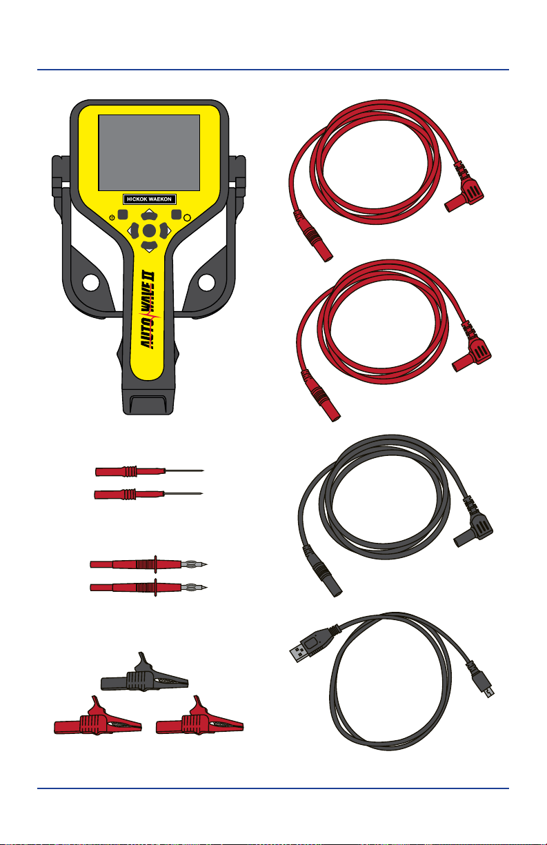
Components
MENU CHNL
?
Test Lead
Test Lead
Test Lead
USB Cable
Auto Wave II
Alligator Clips
Flexible Back Probe Pins
Lantern Tip Test Probes

6
Components
Auto Wave II
Use along with the supplied test leads and accessories. Allows you to view single
or dual waveforms.
Red Test Leads
Two 5ft right angle/straight shielded banana plug test leads for viewing single or
dual waveforms.
Black Test Lead
One 5ft right angle/straight shielded banana plug test lead for ground.
Note: A good ground connection is required for obtaining clean waveforms.
USB Cable
One 3ft standard A male to mini-B USB cable. Cable is used to download Large
and Small saved BMP waveform images for viewing on a PC.
Flexible Back Probe Pins
Two red female shielded exible slip on back probe pins.
Lantern Tip Test Probes
Two red male banana plug tip test probes. Attach female banana plug test
accessories to the tips or use as standard test probes.
Alligator Clips
Two red and one black female banana plug slip on alligator clips.

7
Controls and ConnectionsControls and Connections
Front View
On-O / Menu Button
To power on Auto Wave II — press and release the On-O / Menu button.
To access the Main Menu — press and release the On-O / Menu button with the
unit on.
• Press and release the Menu button again to return.
To power o Auto Wave II — press and hold the On-O / Menu button.
• Auto Wave II automatically turns off after 2-minutes of no activity.
Help / Channel Button
To display help on the current operation — press and release the Help /Channel
button at any time.
• Continue to press and release the Help button to scroll through the
pages (if there is more than one) and to return to the current operation.
To toggle between channel CH-1 and CH-2 for adjustments when viewing dual
waves—press and release the Help / Channel button.
MENU CHNL
?
Help/ Channel
On-O / Menu
Navigation Buttons (up, down, left, right)
LCD Screen
Select Button

8
Controls and Connections
Select Button
The function of this button varies depending on use and the mode of operation
you are currently in.
Press and release to:
•Select Main Menu items.
• Toggle between Zoom and Pan modes.
Press and hold to:
• Capture and save the currently displayed wave.
• Display a list of options (Resume, Bitmap, Cancel, Delete) while viewing
saved waveforms.
Navigation Buttons
The function of this button varies depending on the mode of operation you are
currently in.
Up, Down, Left, Right buttons are used to:
• Navigate Main Menu items.
• Adjust time and voltage scales when viewing live or saved
waveforms (ZOOM).
• Move waveform left, right, up or down when viewing live or saved
waveforms (PAN).
• Toggle through File List and Browse Waves menu items.
• Clear Min / Max values in Voltmeter mode.
• Select Voltage Ranges, Trigger Mode, Trigger Using, Trigger Level and
Coupling modes.
See Main Menu and How To sections for more detail
9
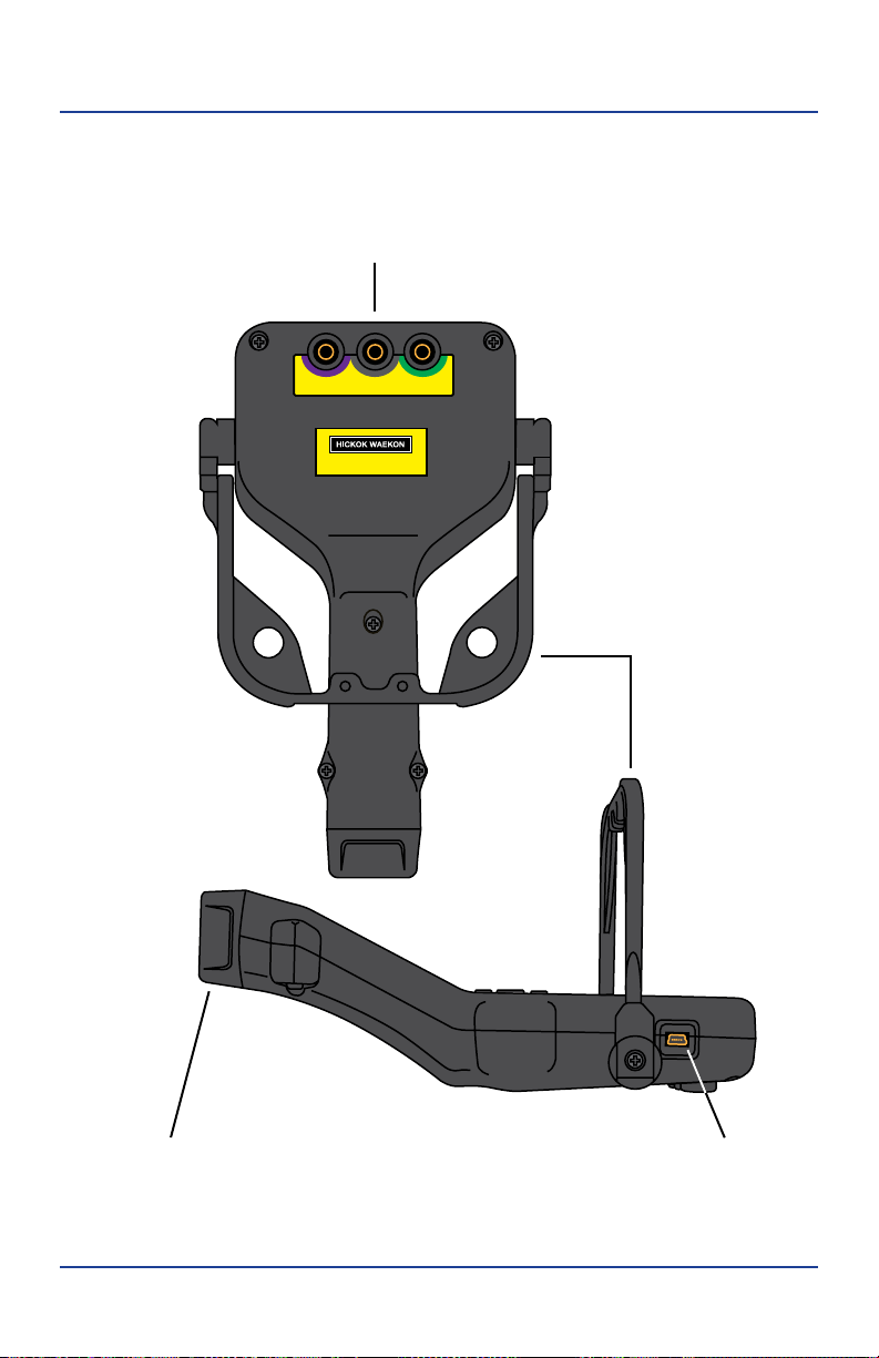
Controls and Connections
CH 2 CH 1GND
www.hickokwaekon.com
Input Jacks
CH-2, GND, & CH-1
Mini USB Port9V Battery Compartment
Hanger / Stand
Back View
(Right Side View)
10
Controls and Connections
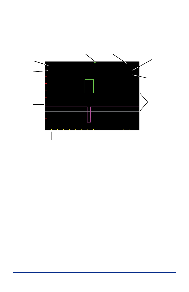
LCD Screen Symbols and Indicators
ZOOM
CH-1
T=2 mS
V1= 2V
V2= 1V
Active PAN /
ZOOM
Time Divisions
(yellow)
Trigger
Indicator
Voltage
Divisions
(red)
Zero Voltage
Lines (gray)
Time Scale
(Yellow) Channel 1
Voltage Scale
(green)
Channel Channel 2
Voltage Scale
(purple)
11
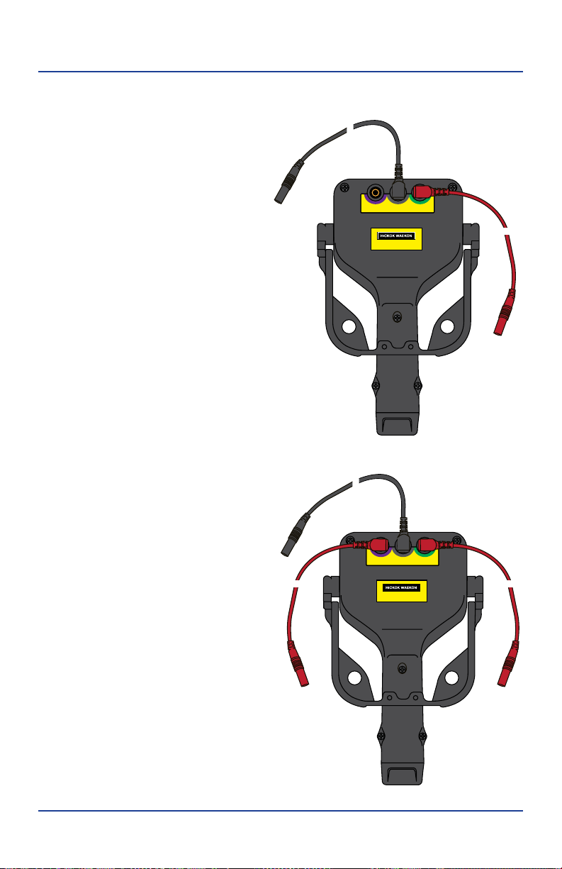
Setup Procedure
For One Channel Use
• Plug red test lead into CH-1
input jack.
• Plug the black test lead intothe
groundjack.
For Two Channel Use
• Plug red test leads into CH-1
and CH-2 input jacks
• Plug black test lead into the
ground jack.
Note: When using the test leads, make
sure to keep them away from high
noise sources to prevent noise
coupling into the wire and aecting
the signal clarity being viewed.
Black
Test Lead
(GND)
Red Test Lead
(CH-1)
Black
Test Lead
(GND)
Red TesT Lead
(CH-2)
Red Test
Lead (CH-1)
CH 2 CH 1GND
www.hickokwaekon.com
CH 2 CH 1GND
www.hickokwaekon.com
12
Setup Procedure
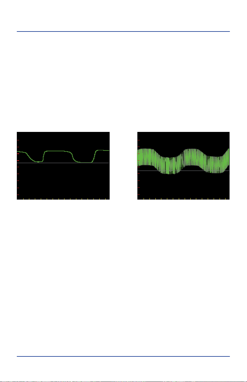
Why Ground Hookup Is Important
• Connecting a good ground point is important for obtaining clean
waveforms.
• For most vehicle signals, the battery negative terminal or the engine
block will provide a clean ground.
• A bad ground, such as the vehicle chassis, may add false noise
to the signal.
The same O2 sensor signal with the Ground Cable connected in two dierent places:
ZOOM
CH-1
T=400 mS
V1= 500mV
ZOOM
CH-1
T=400 mS
V1= 300mV
Good Ground Bad Ground

13
How To…
View a Live Waveform
Basic overview on how to use Auto Wave II.
• Determine the setup you require (one or two channels) and connect the
black test lead to a good ground on the vehicle.
• Turn Auto Wave II on and probe the desired electrical signal or voltage
on the vehicle. A waveform should appear on the LCD screen indicating
the presence of a signal.
• If needed, go to the Main Menu and select Auto-Set.
• If needed, go to the Main Menu and adjust Trigger Mode.
• If needed, go to the Main Menu and adjust Trigger Level.
• If needed, go to the Main Menu and adjust Coupling.
Zoom or Pan While Viewing Live or Saved Waveform
Press and release the navigation buttons to Zoom or Pan the screen view.
Zoom
• Left button decreases (Zoom in) the time setting (T=)
• Right button increases (Zoom out) the time setting (T=)
• Up button decreases (Zoom In) the voltage setting (V=)
• Down button increases (Zoom out) the voltage setting (V=)
Pan
•Use the Navigation buttons to move the screen view in the desired direction.
Note: The time and voltage scale setting used during live waveform viewing sets
the sample rate and the saved waveforms length.
Capture and Save a
Waveform
A waveform can be captured and saved for further review.
• While viewing a live waveform,
press and hold the Select button to
capture and save it.
• A yellow box appears around
the waveform and displays the
assigned filename (i.e. WAVE0025).
• To view saved waveforms on a PC
ZOOM
Saving...WAVE0001
CH-1
T=500 uS
V1= 10V
14
How To…
they will need to be saved as a
Bitmap file (See Create Bitmaps).
• To return to live waveform
viewing, press and hold Select
until the file options list appears
and then select RESUME.
Note: A saved waveform’s resolution is
determined by the Time and Voltage
settings at the time a waveform is
captured and cannot be adjusted once
saved.
Create Bitmaps
While viewing saved waves, create
a customized bitmap to show the
attributes of a captured waveform for
viewing on a PC.
• Position the waveform using
ZOOM/PAN, then hold down
the Select button until the File
Option list appears.
• Select BITMAP and wait for the
process to complete.
• Adjusting the ZOOM/PAN and resaving the file will overwrite the
previous bitmap.
Note: Once saved, the bitmap retains the same lename except with a .BMP extension.
(LARG0000.BMP, SMAL0000.BMP)
View Saved
Waveforms
Access and view saved waveforms on Auto Wave through the Main Menu
options, on your PC, or immediately after saving a waveform.
Saved waveform le options
Press and hold the Select button to view the le options.
• Resume — Returns to the previous live settings
• Bitmap — Creates and saves a le as a bitmap (required for viewing on a PC)
ZOOM
CH-1
T=1 mS
V1= 5V
RESUME
BITMAP
CANCEL
DELETE
ZOOM
CH-1
T=1 mS
V1= 5V
RESUME
BITMAP
CANCEL
DELETE

15
How To…
• Cancel — Exit file option list (no action)
• Delete — Deletes the current saved waveform (cannot be undone).
• Press and release the Select button to choose desired option.
Viewing saved waveforms
Choose the waveform to be viewed and press Select.
• Voltage and time settings are shown as they appeared when the
waveform was saved.
• Zoom and Pan functions can be used to get a more detailed view of
the waveform.
• To view additional waveforms press and release the Menu button to be
returned to the last Main Menu item selected.
• To exit viewing saved waveforms, press and hold the Select button.
Selecting RESUME will take you back to the live waveform viewing screen.
Viewing waveforms saved as Bitmaps on a PC
• Insert USB mini end of the cable into USB port on the side of the Auto
Wave II.
• Insert other standard size A end of USB Cable into PC USB port.
• Select USB File Access from the Main Menu once the USB cable is
connected to both.
• It may take up to a minute for full access to AUTOWAVE II media storage
drive.
• Files saved as Bitmaps will have the .BMP le extension (ie. LARG0007.
BMP,SMAL0007.BMP).
• When nished, eject the media storage drive from the PC. Then unplug
the USB cable.
IMPORTANT! It is recommended to only delete the WAVEFILE.DAT le if the media
becomes corrupted or les are missing. Deleting this le forces the unit to scan all
les and rebuild the missing or corrupted les.
Note: The rst time you plug the USB Cable into your PC it may need to load
drivers. Drivers are standard Microsoft Interface Drivers and should already be
available on your PC.

16
How To…
Replace the
B
a
tt
er
y
Auto Wave II uses a 9V Alkaline battery located in the bottom of the handle.
• Hold unit with LCD screen facing down and remove bottom plug.
• Lift the battery off the retainer ledge and slide battery out.
• Locate the plus (+) symbol in front of the retainer ledge and install the
new battery with the + side to the right.
• Push down to snap the battery in behind the retainer ledge.
• Re-insert the bottom plug.
Note: Not all 9V batteries are exactly the same size. While most will t correctly
you may nd one that does not snap in. Do not force the battery into the handle
as you may damage the internal connectors.

17
Main Menu Functions
Main Menu Functions
Main Menu
The Main Menu is available at ay time by pressing and releasing the Menu button.
• Use the Up/Down Navigation
buttons to scroll through the
menu.
• Use the Left/Right Navigation
buttons to change the item with an
> next to them.
• Press and release the Select button
to select or change the item.
• Press and release the Menu button
again to return to the previous
mode.
Auto-Set
Performs automatic time and voltage scales adjustment.
• Connect Black Test Lead to known good ground.
• Connect Red Test Lead(s) to
desired signals or voltages.
• Go to the Main Menu and select
Auto-Set.
• During the process the percent
progress is displayed on the top
of the LCD next to the Time/
Voltage scale.
• Make sure to keep the Red Test
Lead(s) in contact with the signal until it completes.
• Press and release Select at any time to abort the process leaving Auto
Wave II at the current settings.
MAIN MENU
AUTO-SET
VOLT METER
FILE LIST
BROWSE WAVES
BATTERY STATUS > ALKALINE
DELATED CAPTURE
USB FILE ACCESS
VOLTAGE RANGE > DEFAULT +/– 100V
TRIGGER MODE > AUTO
TRIGGER USING > CH-1 SINGLE WAVE
TRIGGER LEVEL > 50% FALLING
COUPLING > CH-1=DC
ZOOM 27%
CH-1
T=10 mS
V1=200mV

18
Main Menu Functions
Volt Meter
Provides basic auto-ranging digital volt meter functionality to read D/C or True
RMS A/C voltage.
• Volt readings are updated 40/sec.
• The voltage reading is displayed
in the NOW box.
• MAX and MIN boxes represent
the highest and lowest voltages
seen in the NOW box.
• Press and hold the Left/Right
navigation buttons to change
A/C or D/C voltage reading.
• To clear the MAX value, press and release the Up button. To clear the MIN
value, press and release the Down button.
• To clear NOW value, press and hold the Select button. Press and release
the Select button a second time to clear MAX/MIN values at the same
time.
Note: For very low millivolt measurments zero the volt meter by connecting
(short) the Black and Red Test leads together, press and hold the Select button
until the digits read 0.000.
File List
Displays a list of the waveform les currently stored in the Auto Wave II.
• Use the up/down navigation
buttons to scroll through the list
one file at a time or use the left/
right buttons to scroll by page.
• Press and release the Select
button to load the file for
viewing.
• Press and hold the Select button
to display a list of file options.
• The total number of saved
waveform files is shown at the
bottom of the LCD.
VOLT METER
AC
MAX
NOW
MIN
VDC
VDC
VDC
DC
RUN
DC VOLTS
–0.001
– 00.2
–0.001
SAVED WAVE FILE LIST
TOTAL SAVED = 6
WAVE0001
WAVE0002
WAVE0003
WAVE0004
WAVE0005
WAVE0006

19
Main Menu Functions
Browse Waves
Displays a graphical preview of each waveform.
• Use the Left/Right Navigation buttons to preview the saved waveforms.
• Press and release Select to load the file for viewing.
• Press and hold the Select button to display a list of file options.
Battery Status
Displays the current battery charge level in percent and shows battery voltage.
• Auto Wave II needs 6V or more to
operate. When the percentage
charge reaches 0% the Battery
needs to be replaced.
Note: The Battery Charge status has two
options Alkaline or Li-lon (rechargeable).
Choose the appropriate setting based
on style of battery being used. Alkaline is
the default setting.
Delayed Capture
Sets a 10 second timer to automatically
capture the waveform.
• When viewing a live waveform
make any necessary adjustments
to the time/voltage scales and
triggering.
• Go to the Main Menu and select
Delayed Capture.
• A large countdown number
appears in the upper top center of the LCD display showing the seconds
remaining until capture (starts at 10 sec.).
• When the countdown reaches zero the waveform is captured and saved.
Note: Delayed Capture only works on a time base between 50 mS-100 uS.
3%
BATTERY CHARGE
ALKALINE ALKALINE LI_ION
6.11V
ZOOM
CH-1
T=20 mS
V1= 200mV
3

20
Main Menu Functions
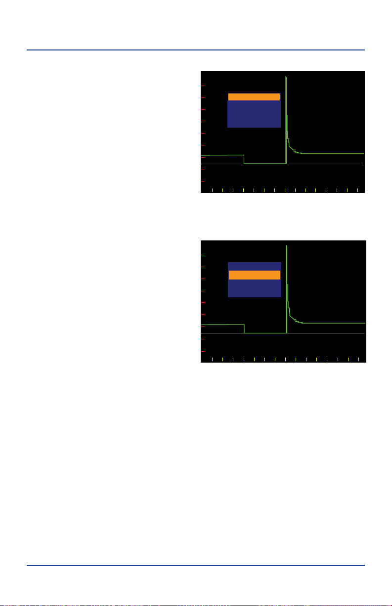
USB File Access
Allows access to Auto Wave II media storage drive for viewing saved Bitmaps les
on a PC.
• Two files are created when a waveform is saved as a Bitmap.
• The LARG0000.BMP larger 4096x1024 pixel file is a detailed panoramic
view of the waveform. The SMAL0000.BMP is a smaller 320x240 pixel file
which is actual LCD size view of the waveform.
• Files viewed on a PC may be renamed and saved to the PC only.
Note: The WAVA0000.TXT & WAVB0000.TXT les are the raw wave data les used
by Autowave II for storing/viewing saved waves. They cannot be viewed on a PC.
Voltage Range
Used to select voltage range of both channels. Highlight Voltage Range on the
Main Menu and use the Left/Right Navigation buttons to change then press
Select button to set.
• Default +/- 100V
• Negative -200V
• Positive +200V
Note: Voltage Range selections are 200V maximum.
Trigger Mode
Use to enhance the acquisition and visibitly of live waveforms. Highlight Trigger
Mode on the Main Menu and use the Left/Right Navigation buttons to change
then press Select button to set.
• Auto
• Manual
Trigger Using
Use to change Single or Dual channel viewing. Highlight Trigger Using on the
Main Menu and use the Left/Right Navigation buttons to change then press
Select button to set.
• CH-1 Single Wave - Trigger uses channel 1
• CH-2 Dual Waves - Trigger uses channel 2 with dual waveforms
• CH-1 Dual Waves - Trigger uses channel 1 with dual waveforms
Table of contents
Other Hickok Test Equipment manuals


