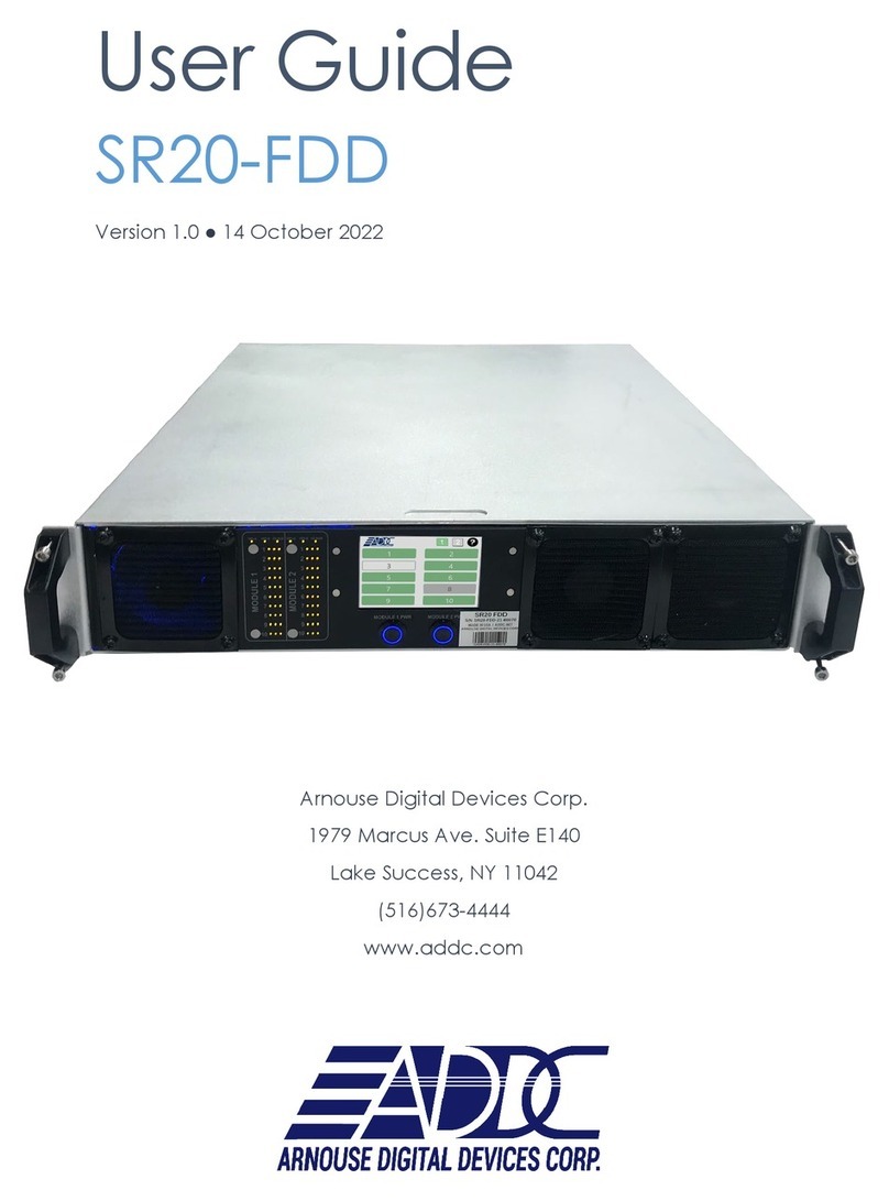
ADDC SR10-FDD User manual

User Guide
SR10-FDD
Version 1.0 ● 09 February 2021
Arnouse Digital Devices Corp.
1983 Marcus Ave, Suite 104
Lake Success, NY 11042
(516)673-4444
www.addc.net

Revision Notes
V1.0 Revision 1.0 was published in December 2020

Arnouse Digital Devices User Guide
SR10-FDD Version 1.0
© Arnouse Digital Devices 2021. All rights reserved.
Page 3 of 26
© 2020 Arnouse Digital Devices Corp (ADDC). All rights reserved.
Arnouse Digital Devices Corp. 1983 Marcus Ave, Suite 104, Lake Success, NY 11042
(516)673-4444, www.addc.net
Trademarks
SR10-FDD and BioDigitalPC®are registered trademarks of Arnouse Digital Devices Corp. All other
trademarks or registered trademarks are the property of their respective owners.
Disclaimer
The information provided in this document is provided "as is" without warranty of any kind. ADDC
disclaims all warranties, either express or implied, including the warranties of merchantability and
fitness for a particular purpose. In no event shall ADDC be liable for any damages whatsoever
including direct, indirect, incidental, consequential, loss of business profits or special damages, even if
ADDC or its suppliers have been advised of the possibility of such damages.
Document Lifetime
ADDC may occasionally update online documentation between releases of the related hardware and
software. Consequently, if this document was not downloaded recently, it may not contain the most
up-to-date information. Please refer to www.addc.net for the most current information.
From the Web site, you may also download and refresh this document if it has been updated, as
indicated by a change in this date: 20 December 2020.
Where to get help
ADDC support, product, and licensing information can be obtained as follows.
Product information — Documentation, release notes, software updates, and information about
ADDC products, licensing, and service, are at ADDC website at:
http://wwwaddc.net
Technical support — Go to http://www.addc.net and select Support. On the Support page, you will
see several options, including one for making a service request. Note that to open a service request,
you must have a valid support agreement.
Your comments
Your suggestions will help us continue to improve the accuracy, organization, and overall quality of the
user publications. Please send your opinion of this document to:
Documentation@addc.net
If you have issues, comments, or questions about specific information or procedures, please include
the title and, if available, the part number, the revision, the page numbers, and any other details that
will help us locate the subject that you are addressing.

Arnouse Digital Devices User GuideSR10-FDD User Guide-V1.0_12-21-2020.docx
SR10-FDD Version 1.0
© Arnouse Digital Devices 2021. All rights reserved. Page 4 of 26
Table of Contents
1Introduction ............................................................................................................ 6
1.1 Purpose …...……………………………………………………………………………………… 5
1.2 Scope ……...……………………………………………………………………………………... 5
1.3 System Organization ……………………………………………………………………………. 5
2System Description ................................................................................................ 7
2.1 Key Features.......................................................................................................... 7
2.2 System Inventory.................................................................................................... 7
2.3 Environment ......................................................................................................... 10
2.4 System Operations............................................................................................... 10
3Installing, Starting and Stopping the System........................................................ 11
3.1 Installing the System ............................................................................................ 11
3.2 Installing the SR10-FDD Into a Rack.................................................................... 11
3.3 Installing System Components............................................................................. 11
3.4 Networking the System ........................................................................................ 17
4Step by Step Operating Instructions..................................................................... 19
4.1 SR10-FDD Overview............................................................................................ 19
4.2 SR10 Modules...................................................................................................... 20
5ROMWare Lite Software ...................................................................................... 22
5.1 Login .................................................................................................................... 22
5.2 Main Web GUI Screen Overview.......................................................................... 22
5.3 PC Card Power Control and Monitoring ............................................................... 22
5.4 Front Panel Touchscreen Overview ..................................................................... 22

Arnouse Digital Devices User Guide
SR10-FDD Version 1.0
© Arnouse Digital Devices 2021. All rights reserved.
Page 5 of 26
List of Figures
Figure 1- SR10-FDD System Block Diagram .................................................................. 7
Figure 2- SR10-FDD Chassis.......................................................................................... 9
Figure 3- Cable Management Arm .................................................................................. 9
Figure 4- 10Gbps SFP+ Cables ...................................................................................... 9
Figure 5- AC Power Cord ................................................................................................ 9
Figure 6- AC/DC Power Supply....................................................................................... 9
Figure 7- BioDigitalPC®................................................................................................... 9
Figure 8- SR10-FDD Rear Panel .................................................................................. 12
Figure 9- PC Card Fully Inserted and Locked ............................................................... 12
Figure 10- PC Card Track Setup................................................................................... 12
Figure 11- PC Card Track ............................................................................................. 13
Figure 12- PC Card Locking Mechanism....................................................................... 13
Figure 13- SR10 PC Card Unlocking............................................................................. 14
Figure 14- SR10 PC Card Ejection................................................................................ 14
Figure 15- PC Card ejection lever position.................................................................... 16
Figure 16- KVM PCB Stack Modules ............................................................................ 16
Figure 17- KVM PCB Power Cable ............................................................................... 16
Figure 18- SR10-FDD AC/DC Power Supply ................................................................ 16
Figure 19- SR10-FDD Switch Management Ports......................................................... 17
Figure 20- SR10-FDD Ethernet Networking Ports......................................................... 17
Figure 21- SR10-FDD Ethernet Networking Ports (Recommended Configuration)....... 18
Figure 22- SR10-FDD Front Panel................................................................................ 18
Figure 23- SR10-FDD Front Panel Controls and Indicators .......................................... 19
Figure 24- SR10-FDD Rear Panel Connections............................................................ 19
Figure 25- SR10 Block Diagram.................................................................................... 20
Figure 26- SR10-FDD Front Panel................................................................................ 21

Arnouse Digital Devices User GuideSR10-FDD User Guide-V1.0_12-21-2020.docx
SR10-FDD Version 1.0
© Arnouse Digital Devices 2021. All rights reserved. Page 6 of 26
1Introduction
1.1 Purpose
The purpose of this document is to define the functionality, operation, and maintenance of the
SR10-FDD Data Center. This document serves as the sole reference for the system
functionality at time of delivery. Any change to the Functional Specifications will require
agreement via the change control process between the user and ADDC. The SR10-FDD was
designed to provide long range (up to 24 km) remote operation via fiber optic cable KVM of up
to 10 BioDigitalPC®computers.
1.2 Scope
Summarize the purpose and contents of this guide and describe any security or privacy
considerations associated with its use.
This guide has 3 main sections, system functional specifications, operation, and maintenance.
The maintenance section requires that only qualified technicians gain access to the internal
components of the system. The system’s power management controls via the front panel touch
screen or the ROMWare GUI are PIN and password protected for security.
1.3 System Organization
Figure 1 is the block diagram for the SR10-FDD system. The system consists of the following
main components:
• SR10 Module
• AC-DC 12V Power Supply (main power source for SR10 Module and fans)
• DC-DC 12V-5V Converter (power for all KVM modules)
• ROMWARE Lite Module (provides remote power control of each individual PC Card)
• ROMWARE Lite Software (provides touch screen control and/or web GUI remote power
control)

Arnouse Digital Devices User Guide
SR10-FDD Version 1.0
© Arnouse Digital Devices 2021. All rights reserved.
Page 7 of 26
Figure 1- SR10-FDD System Block Diagram

Arnouse Digital Devices User GuideSR10-FDD User Guide-V1.0_12-21-2020.docx
SR10-FDD Version 1.0
© Arnouse Digital Devices 2021. All rights reserved. Page 8 of 26
2System Description
The SR10-FDD combines the power of the ADDC SR10 module with the Made in the USA, long
distance, fiber KVM (Keyboard, Video, Mouse) terminal for extraordinary capability. The SR10
module specifically designed to be integrated into a SR10-FDD features 10 separate and
distinct computers with USB and video delivered through fiber KVM. Each computer is
connected to a high-speed layer 2 managed switch through 3 physical 1 GbE NICs. The
embedded switch manages the individual NICs and has two 10G SFP+ trunk ports. Serial and
HTTP based switch management is included. Individual auto and remote computer power
control.
2.1 Key Features
The SR10-FDD System provides the following key features:
•10 Separate BioDigitalPC®Cards that can be easily remove and replaced for ease of
maintenance and upgradeability.
•Remote power control for each individual PC Card via a web GUI to allow remote
resetting of the PC Card.
•Each PC Card has its own KVM over fiber adapter to allow an additional remote
operation of the PC Card and its software applications.
2.2 System Inventory
The SR10-FDD system ships with the following components:
•SR10-FDD Chassis (Figure 2)
•1 each Cable Management Arm (Figure 3)
•2 each 10Gbps SFP+ Cables (Figure 4)
•1 each AC power Cord (Figure 5)
•1 each AC/DC Power Supply (Figure 6)
•BioDigitalPC®Cards (Check Invoice for Quantity) (Figure 7)

Arnouse Digital Devices User Guide
SR10-FDD Version 1.0
© Arnouse Digital Devices 2021. All rights reserved.
Page 9 of 26
Figure 2- SR10-FDD Chassis
Figure 3- Cable Management Arm
Figure 4- 10Gbps SFP+ Cables
Figure 5- AC Power Cord
Figure 6- AC/DC Power Supply
Figure 7- BioDigitalPC
®

Arnouse Digital Devices User GuideSR10-FDD User Guide-V1.0_12-21-2020.docx
SR10-FDD Version 1.0
© Arnouse Digital Devices 2021. All rights reserved. Page 10 of 26
2.3 Environment
The system is intended to be used in an environmentally controlled and secured facility. The
following system components are required for installation and remote-control operation.
•Rack Slides (not provided)
•Remote KVM Transceiver Unit (purchased separately)
•Fiber Optic cable (length determined by the end user)
•Laptop or PC with an Ethernet NIC for Remote Control Operation
•Laptop or PC with a Serial Communications Port for Switch Management
•Routers with 10G SFP+ Port
2.4 System Operations
The SR10-FDD can operate unattended once is properly installed and configured for remote
KVM operation. The remote users can have as much control of each PC Card as allowed by the
system administrator. Each user may be able to login and logout of the PC Card and operate
applications also as allowed by the System Administrator. However, System power controls and
switch management functions are not available to the user and must be accomplished from a
PC or laptop connected to the power and switch management ports on the rear panel of the
unit. These functions are password protected and available only to the System Administrator.

Arnouse Digital Devices User Guide
SR10-FDD Version 1.0
© Arnouse Digital Devices 2021. All rights reserved.
Page 11 of 26
3Installing, Starting and Stopping the
System
3.1 Installing the System
When installing the SR10-FDD into a rack, the selected location should meet environmental
standards as described below.
Rack Space and Airflow Considerations
To allow for adequate airflow, technicians should observe the following space and airflow
requirements when deciding where to install a rack.
• Leave a minimum clearance of 36in (91.4cm) in front of the rack.
• Leave a minimum clearance of 20in (50.8cm) behind the rack.
Temperature Considerations
Your SR10-FDD is designed to operate at room temperature with its self-contained cooling.
Power Considerations
When properly configured and installed the SR10-FDD can draw up to 500 Watts depending on
the number, load, and version of the BioDigitalPC®s used.
•To prevent improper cooling of equipment, do not block the fans.
•Clean the front fan filters periodically (at least once a month).
•If the system is intended to operate from an Uninterrupted Power Supply (UPS) power
source, ensure that the UPS unit has enough capacity to run the system.
3.2 Installing the SR10-FDD into a rack
The SR10-FDD does not ship with rack rails. The rails must be provided by the end user; follow
the rail and rack manufacturers installation instructions.
3.3 Installing System Components
BioDigitalPC®s are hot-pluggable, meaning technicians do not need to remove power to begin
adding or removing them.
Note: Only trained technicians are authorized to work inside the SR10-FDD System and access
any of the components inside the system.

Arnouse Digital Devices User GuideSR10-FDD User Guide-V1.0_12-21-2020.docx
SR10-FDD Version 1.0
© Arnouse Digital Devices 2021. All rights reserved. Page 12 of 26
3.3.1 Removing the SR10-FDD Top Cover
To add or remove BioDigitalPC®s, the SR10-FDD chassis must be pulled out of the rack, and
the SR10-FDD's Top Cover needs to be removed temporarily.
Warning: The SR10-FDD can be running while installing new server cards. However,
caution must be taken to prevent damage to the equipment as exposed circuit
components may short if any metal objects are inadvertently dropped inside the chassis.
Future versions of all electronic components will be conformal coated to prevent this from
happening.
Figure 8- SR10-FDD Rear Panel
•Step 1- Remove the center Phillips head screw.
•Step 2- Slide the top cover to the rear and lift to release the cover from the 4 side locking
pins.
3.3.2 Installing a BioDigitalPC®
Figure 9- PC Card Fully Inserted and locked
•Step 1- Make the PC Card ejection lever is perpendicular to the system cover.
•Step 2- Make sure locking tab is unlocked.
Figure 10- PC Card Track Setup
PC Card Ejection Lever Small locking tab

Arnouse Digital Devices User Guide
SR10-FDD Version 1.0
© Arnouse Digital Devices 2021. All rights reserved.
Page 13 of 26
•Step 3- Insert Card with “Arnouse Digital Devices Corp.” facing upwards and the
connector of the card is facing towards the PC Card ejection lever. When inserting the
card, place it between the two horizontal metal bars, ensuring the card is going to be
aligned properly.
Figure 11- PC Card Track
•Step 4- Once the card is in between the two horizontal bars, locate the small locking tab
and push it in towards the PC Card until the tab locks into place.
Figure 12- PC Card Locking Mechanism

Arnouse Digital Devices User GuideSR10-FDD User Guide-V1.0_12-21-2020.docx
SR10-FDD Version 1.0
© Arnouse Digital Devices 2021. All rights reserved. Page 14 of 26
3.3.3 Removing a BioDigitalPC®
•Step 1- Find the locking tab located to the right of the card slot. Unlock the locking tab.
Figure 13- SR10 PC Card Unlocking
•Step 2- Pull the PC Card ejection lever forward towards you, you should feel the card
pop out of the connector.
Figure 14- SR10 PC Card Ejection

Arnouse Digital Devices User Guide
SR10-FDD Version 1.0
© Arnouse Digital Devices 2021. All rights reserved.
Page 15 of 26
•Step 3- Reset the ejection lever to the original position to make the PC Card removal
easier.
Figure 15- PC Card ejection lever position
3.3.4 Replacing a KVM Over Fiber PCB Stack Module
•Disconnect all cables (USB, miniDP, 5V power, and Fiber Optic)
•Remove 4 Phillips pan head 4-40 X ¼” screws located at the bottom of each corner of
the module (see Figure 12).
•Remove the KVM PCB Stack Module from the chassis.
•Install the KVM PCB Stack Module in reverse order as removal.
Warning: The 5V power cable must be installed with the proper polarity (see Figure 13).
Connecting the 5V power cable with reverse polarity will severely damage the KVM PCB.
Figure 16- KVM PCB Stack Modules Figure 17- KVM PCB Power Cable
USB Cables
Fiber Cables
miniDP Cables
(not installed)
+ Positive (red wire)
located to the rear
close to the USB
connector
- Negative
(black wire)
located to the
front close to
the fiber cable
transceiver
4-40 X ¼”
Phillips head
screws, 4 per
KVM module

Arnouse Digital Devices User GuideSR10-FDD User Guide-V1.0_12-21-2020.docx
SR10-FDD Version 1.0
© Arnouse Digital Devices 2021. All rights reserved. Page 16 of 26
3.3.5 Replacing the SR10-FDD Top Cover
Once complete, a technician should replace the SR10-FDD top cover following the 2-step
removal process in reverse order.
3.3.6 Installing the AC/DC Power Supply
Figure 18- SR10-FDD AC/DC Power Supply
•Step 1- Push the AC power supply straight into the power supply cavity. Ensure the
power supply is oriented properly and that the locking tab engages inside the cavity.
•Step 2- Connect the AC power cord into the power supply and connect it to a 20 Amp
AC outlet. The green power “OK” LED should illuminate.
3.3.7 Removing the SR10-FDD Power Supply
•Refer to Figure 14.
•Step 1- Turn off power to the system and disconnect the AC power cord.
•Step 2- Push the locking tab to the left to release the power supply.
•Step 3- Pull on the power supply handle to remove it.
Handle
Locking Tab

Arnouse Digital Devices User Guide
SR10-FDD Version 1.0
© Arnouse Digital Devices 2021. All rights reserved.
Page 17 of 26
3.4 Networking the system
3.4.1 Minimal/Testing Equipment
•1 each 10/100 Ethernet Cable
•1 each Cisco compatible RS232 Serial Communications Cable
•1 each External Computer (e.g., a laptop)
Figure 19- SR10-FDD Switch Management Ports
3.4.2 1Gbps Networking Schema
•1 each 10/100 Ethernet Cable
•1 each Cisco compatible RS232 Serial Communications Cable
•1 each 10/100/1000 Ethernet Cable
•1 each 10 port (or more) 10/100/1000 Ethernet Switch
Figure 20- SR10-FDD Ethernet Networking Ports

Arnouse Digital Devices User GuideSR10-FDD User Guide-V1.0_12-21-2020.docx
SR10-FDD Version 1.0
© Arnouse Digital Devices 2021. All rights reserved. Page 18 of 26
3.4.3 10Gbps Networking (with ROMWare Switch
Management)
•This is the recommended SR10-FDD Networking Configuration
•1 each 10/100 Ethernet Cable
•1 each Cisco compatible RS232 Communications Cable
•1 each 4 port (or more) 10/100 Ethernet Switch
•1 or 2 10Gbps SFP+ Cables
Figure 21- SR10-FDD Ethernet Networking Ports (Recommended Configuration)
3.4.4 SR10-FDD Power ON and OFF
•Connect SR10-FDD to a 20 Amp AC power receptacle.
•Press the ON/OFF Power Button on the front panel.
•The blue ring LED on the power button should illuminate.
•Pressing the power button again will turn OFF the system.
Figure 22- SR10-FDD Front Panel
Power Button

Arnouse Digital Devices User Guide
SR10-FDD Version 1.0
© Arnouse Digital Devices 2021. All rights reserved.
Page 19 of 26
4Step by Step Operating Instructions
This section outlines the step-by-step procedure for system power ON/OFF and remote-control
operation via the ROMWare Lite GUI.
4.1 SR10-FDD Overview
Figure 23- SR10-FDD Front Panel Controls and Indicators
Figure 24- SR10-FDD Rear Panel Connections
Power Button
LED NIC
Activity Indicators
LCD Touchscreen
Fan Filters
KVM Fiber Optic
Cable Couplers
AC/DC Power
Supply Power OK
Indicator
AC/DC Power
Supply Power
Failure Indicator
10 Gbps SFP+
Ports
Switch Management,
Power Management
and 1G Ethernet Ports

Arnouse Digital Devices User GuideSR10-FDD User Guide-V1.0_12-21-2020.docx
SR10-FDD Version 1.0
© Arnouse Digital Devices 2021. All rights reserved. Page 20 of 26
4.2 SR10 Modules
As shown in the Section 3, the SR10-FDD consists of a single SR-10 Module and 10 KVM over fiber
PCBs. The SR-10 Module contains 10 BioDigitalPC®slots, each having three 1Gbps NICs attached to an
integrated switch. The integrated switch has two SFP+ 10Gbps connectors and one 1Gbps RJ-45
connector broken out to the rear panel of the SR10-FDD (See Section 3.4for additional information).
Each SR-10's BioDigitalPC®power control is managed via the SR10-FDD's Web-based management
program called ROMWare Lite (See Section 5for additional information).
Figure 25- SR10 Block Diagram
4.2.1 Front Panel
Table of contents
Other ADDC Storage manuals
