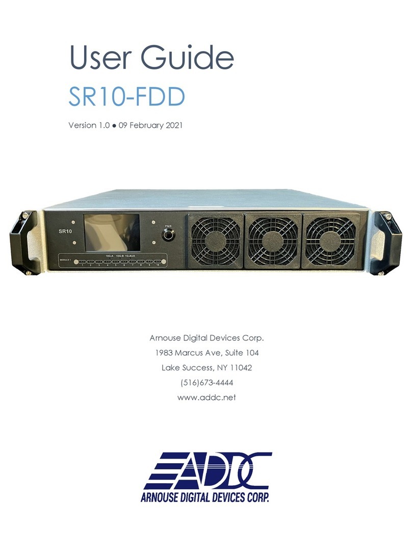
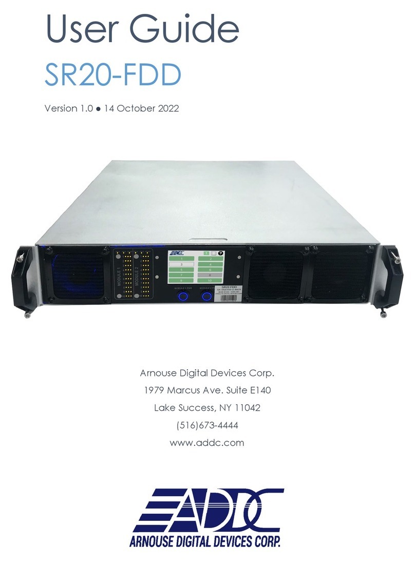
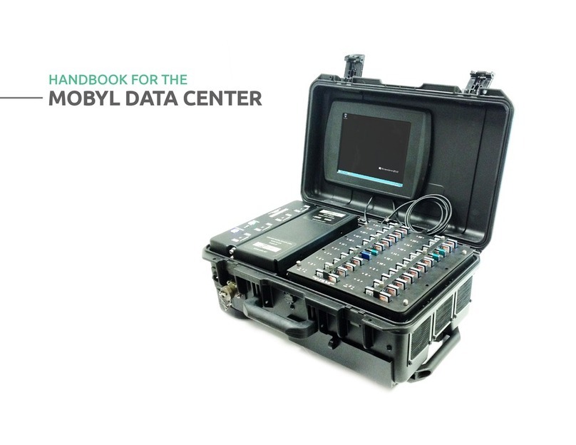
ADDC MDC-SR10-V2 User manual

MDC-SR10-V2
USER GUIDE
PLUG INTO THE FUTURE OF TECHNOLOGY

2
WWW.ADDC.COM | 516.673.4444 | INFO@ADDC.NET | ALL PRODUCTS ARE PROUDLY MADE IN THE USA
Revision History
Revision Notes
V1.0 Revision 1.0 was published in
November of 2023.

3
WWW.ADDC.COM | 516.673.4444 | INFO@ADDC.NET | ALL PRODUCTS ARE PROUDLY MADE IN THE USA
Table of Contents
Section 1 Receiving Your MDC-SR10-V2 5
Section 1.1 What's in the Box? 5
Section 2 MDC-SR10-V2 Preparation 6
Section 2.1 Preparing For Your MDC-SR10-V2 6
Section 2.2 Installing Your BioDigitalPC®s7
Section 2.3 Connect Antennas and Power On
Your MDC-SR10-V2
8
Section 3 MDC-SR10-V2 Overview 9
Section 3.1 SR-10 Module 10
Section 3.2 Side Panel 11
Section 3.3 Connect USB and Video 11
Section 3.4 Network LEDs 12
Section 4 ROMware Software 13
Section 4.1 Login 13
Section 4.2 Main Screen Overview 13
Section 4.3 BioDigitalPC® Power Control &
Monitoring
14-16
Section 4.4 MDC-SR10-V2 System Settings 17

4
WWW.ADDC.COM | 516.673.4444 | INFO@ADDC.NET | ALL PRODUCTS ARE PROUDLY MADE IN THE USA
Notes, Important Information & Warnings
This manual details installation of the mobile data center, the components inside of the mobile data center, and
notable features of the MDC-SR10-V2 mobile server solution.
Installations will be supported by ADDC. Unless otherwise specied, all instructions provided in this manual will
assume that a user is a trained technician.
How to Read this Document
You will see this icon throughout the manual intended to point out warnings, important information, and
briey explain any new terminology.

5
WWW.ADDC.COM | 516.673.4444 | INFO@ADDC.NET | ALL PRODUCTS ARE PROUDLY MADE IN THE USA
Equipment (Not Included)
• Laptop or Testing Network
Equipment (Included)
• MDC-SR10-V2 Case
• BioDigitalPC®Server Cards [Check
Invoice for Quantity]
• (1) DC Input Cable
• (1) AC Power Cord
Section 1.1 - What's in the Box?
MDC-SR10-V2 Case
AC Power Cord
a 5-pin Mil-5015 type Circular Connector DC Input Cable
Section 1.0 - Receiving Your MDC-SR10-V2

6
WWW.ADDC.COM | 516.673.4444 | INFO@ADDC.NET | ALL PRODUCTS ARE PROUDLY MADE IN THE USA
Temperature Considerations
Your MDC-SR10-V2 is designed to operate at room temperature with its self-contained cooling.
Power Considerations
When properly congured and installed the MDC-SR10-V2 can draw up to 200 Watts depending on the
number, load, and version of the BioDigitalPC®s used.
To prevent improper cooling of equipment, do not block the fans.
Section 2.1 - Preparing For Your MDC-SR10-V2
Section 2 - MDC-SR10-V2 Preparation

7
WWW.ADDC.COM | 516.673.4444 | INFO@ADDC.NET | ALL PRODUCTS ARE PROUDLY MADE IN THE USA
Section 2.2 - Installing Your BioDigitalPC®s
BioDigitalPC®s are hot-pluggable, meaning technicians do not need to remove power to begin adding or
removing them.
Section 2.2.1 - Opening the MDC-SR10-V2 Case:
Section 2.2.3 - Installing a BioDigitalPC®
Section 2.2.4 - Secure BioDigitalPC® With the Card Holder
Section 2.2.2 - Connect AC Power Cord
Only trained technicians are authorized to work beneath the MDC-SR10-V2 System Cover and
access any of the components inside the system.
Fully inserted card
Insert card into slot
Pull holder up and
rotate it 90°
Lift Clip
Lift Clip
AC Power Input

8
WWW.ADDC.COM | 516.673.4444 | INFO@ADDC.NET | ALL PRODUCTS ARE PROUDLY MADE IN THE USA
Section 2.3 - Connect Monitor and Power On Your MDC-SR10-V2
Power On Button
Mini-DP video cable
needs to be connected
to the monitor.

9
WWW.ADDC.COM | 516.673.4444 | INFO@ADDC.NET | ALL PRODUCTS ARE PROUDLY MADE IN THE USA
Section 2.3 - Connect Monitor and Power On Your MDC-SR10-V2
Power On Button
Network
connections.
Mini-DP video cable
13.3"
touchscreen
display
Card Slot
Number.
USB cable
to enable the
touchcreen.
Display power cable
SR-10
Module
screws to open
storage door. The
storage compartment
is used to store the
power cords.
Section 3 - MDC-SR10-V2 Overview

10
WWW.ADDC.COM | 516.673.4444 | INFO@ADDC.NET | ALL PRODUCTS ARE PROUDLY MADE IN THE USA
As shown in Section 3, the MDC-SR10-V2 consists of a single SR-10 Module. The
SR-10 Module contains 10 BioDigitalPC®slots, each having three 1Gbps NICs
attached to an integrated switch. Each switch has two SFP+ 10Gbps connectors
and one 1Gbps RJ-45 connector broken out to the side panel of the MDC-SR10-V2
(See Section 3.2 for additional information). Each SR-10's integrated switch and
BioDigitalPC® power control are managed via the MDC-SR10-V2's Web-based
management program called: ROMWare (See Section 4 for additional information).
Section 3.1 - SR-10 Module

11
WWW.ADDC.COM | 516.673.4444 | INFO@ADDC.NET | ALL PRODUCTS ARE PROUDLY MADE IN THE USA
Section 3.2 - Side Panel
Section 3.3 - Connect USB and Video
Switch
Management
Port
Power
Management
Port
1Gb AUX Port
AC Power
DC Power
2x10Gbps SFP+ Ports
Internal Switch
Serial Management
Port
Every slot has a dedicated
USB port.
Every slot also has a dedicated
Mini-DP video port.
connect the USB cable
coming out of the storage
compartment to the USB
port on the slot you are
using to activate the touch-
screen on that slot.

12
WWW.ADDC.COM | 516.673.4444 | INFO@ADDC.NET | ALL PRODUCTS ARE PROUDLY MADE IN THE USA
Section 3.4 - Network LEDs
10G-A: SR-10's 10Gbps SFP+ Port Status LED
An individual slot's 1Gbps NIC LEDs. One LED for each 1Gbps NIC
10G-B: SR-10's 10Gbps SFP+ Port Status LED
1G-AUX: SR-10's auxiliary one Gigabit Port Status LED

13
WWW.ADDC.COM | 516.673.4444 | INFO@ADDC.NET | ALL PRODUCTS ARE PROUDLY MADE IN THE USA
The web interface for ROMWare asks for credentials to log in and begin management
and/or monitoring of your MDC-SR10-V2 Users are supplied with administrative
credentials that have been factory set. Only one admin can be logged in at once,
through the IP 10.0.1.254.
Section 4.1 - Login
Section 4 - ROMware Software
Section 4.2 - Main Screen Overview

14
WWW.ADDC.COM | 516.673.4444 | INFO@ADDC.NET | ALL PRODUCTS ARE PROUDLY MADE IN THE USA
Displaying the card management features of the MDC-SR10-V2 is done by clicking the
Slot Number.
Powers on the BioDigitalPC®Server card.
Immediately removes power from the BioDigitalPC®Server card.
Sends a signal to the BioDigitalPC®Server card to shut down gracefully
Removes power from the BioDigitalPC® Server card, waits 30 seconds and then
applies power back to the BioDigitalPC®Server card.
Removes power from the remote power control. Do not use this unless
specically instructed to.
Gracefully reboots the BioDigitalPC®Server card.
Section 4.3 - BioDigitalPC® Power Control & Monitoring

15
WWW.ADDC.COM | 516.673.4444 | INFO@ADDC.NET | ALL PRODUCTS ARE PROUDLY MADE IN THE USA
Section 4.3 - BioDigitalPC® Power Control & Monitoring
BioDigitalPC®Slot Number The unique MDC-SR10-V2 slot number
SR-10 Module Position The position number of the SR-10 Module
within the MDC-SR10-V2
BioDigitalPC®Slot Position The Position of the Slot within the SR-10
Module
Current Status Displays the current status of the slot:
Present, Not Present, On and O
Hardware Information Click "View" to show the Slot Hardware
Information. See the page 21 for more
information.

16
WWW.ADDC.COM | 516.673.4444 | INFO@ADDC.NET | ALL PRODUCTS ARE PROUDLY MADE IN THE USA
Section 4.3 - BioDigitalPC® Power Control & Monitoring
Disable Slot Disables the slot for this SR-10 module.
Is Auto-Power On
Enabled
With this option enabled, after boot up of the MDC-SR10-V2
the BioDigitalPC®in this slot will be powered on (if present)
automatically after the number of seconds specied in the
delay box (below).
Delay The number of seconds to wait after power up of the MDC-
SR10-V2 before powering on the BioDigitalPC®(if present) in
this slot.
MAC Address [1, 2, 3] MAC addresses of the 3 1Gbps NICS for this slot.

17
WWW.ADDC.COM | 516.673.4444 | INFO@ADDC.NET | ALL PRODUCTS ARE PROUDLY MADE IN THE USA
Section 4.4 - MDC-SR10-V2 System Settings
The System Settings allows the user to change four things: ROMware password, the machines
IP address, the machines Gateway and the ability to enable or disable the Keypad
Click on the cog to
access the System
Settings
Other ADDC Storage manuals
