AddEnergie CoRe+ User manual

CoRe+MC/TM
Guide d’installation du système
de rappel des câbles
Cable management system
installation guide

© 2016 ADDÉNERGIE TECHNOLOGIES INC. TOUS DROITS RÉSERVÉS Les informations et les spécications contenues dans ce document sont sujettes aux changements, modications et ajouts à n’importe quel moment et sans préavis.
© 2016 ADDÉNERGIE TECHNOLOGIES INC. ALL RIGHTS RESERVED Information and specications contained in this document are subject to change, amendments and additions at any time, without notice.
2
V1-2017-09-01
Table of contents
Table des matières
Présentation du guide ...................................... 3
Installation murale ....................................... 4
Installation du système de rappel.............................. 6
Installation sur une borne de recharge simple ................ 8
Installation du système de rappel à cordon rétractable............. 10
Installation sur deux bornes de recharge dos à dos........... 11
Installation des deux systèmes de rappel....................... 13
Installation sur deux bornes de recharge côte à côte ......... 14
Installation des supports à borne de recharge côte
à côte et des deux systèmes de rappel......................... 16
Positionnement du serre-câble............................ 19
Installation de l’afche ..................................... 20
Presentation of the guide.................................... 3
Wall mounted installation ................................. 4
Cable management system installation ......................... 6
Single charging station installation ......................... 8
Cable management system installation ........................ 10
Dual back-to-back charging station installation.............. 11
Cable management system installation ........................ 13
Dual side-to-side charging station installation ............... 14
Side-to-side charging station supports and cable management systems
Installation .............................................. 16
Positioning the cable clamp .............................. 19
Positioning the poster panel .............................. 20

© 2016 ADDÉNERGIE TECHNOLOGIES INC. TOUS DROITS RÉSERVÉS Les informations et les spécications contenues dans ce document sont sujettes aux changements, modications et ajouts à n’importe quel moment et sans préavis.
© 2016 ADDÉNERGIE TECHNOLOGIES INC. ALL RIGHTS RESERVED Information and specications contained in this document are subject to change, amendments and additions at any time, without notice.
3
V1-2017-09-01
Le présent guide vise à expliquer l’installation d’un système de rappel à cordon rétractable sur une nouvelle borne de recharge électrique ou sur
un appareil déjà installé.
Le système de rappel des câbles est able, fait d’aluminium et facile à utiliser. Il ne demande aucun entretien et permet de ranger les câbles en
toute sécurité.
Les instructions sont adaptées selon le type d’installation. Il en a quatre types : a) installation murale; b) installation sur borne simple; c)
installation sur bornes doubles dos à dos; d) installation sur bornes doubles, côte à côte. Assurez-vous de vous reporter à la bonne section du
guide, selon le type d’installation que vous vous apprêtez à faire.
Outre les instructions, vous trouverez dans ce guide la liste des pièces qui sont fournies dans l’emballage, selon le type d’installation, ainsi que la
liste d’outils particuliers nécessaires à l’installation le cas échéant.
This guide aims at describing how to install a Cable management system on a new charging station or on a device that has already been
installed.
The Cable management system is reliable, made from aluminum and convenient to use. It’s maintenance free and keeps cables safely off the
ground.
The instructions have been adapted for each type of installation. There are four types: a) wall mounted installation; b) single charging station
installation; c) dual back-to-back charging station installation; d) dual side-to-side charging station installation. Make sure to refer to the proper
section of this guide, according to the type of installation you are about to do.
Other than instructions, you will nd in this guide the list of parts that are included in the package, depending on the type of installation, as well a
list of specic tools or material required to do the work as the case may be.
Introduction / Introduction

© 2016 ADDÉNERGIE TECHNOLOGIES INC. TOUS DROITS RÉSERVÉS Les informations et les spécications contenues dans ce document sont sujettes aux changements, modications et ajouts à n’importe quel moment et sans préavis.
© 2016 ADDÉNERGIE TECHNOLOGIES INC. ALL RIGHTS RESERVED Information and specications contained in this document are subject to change, amendments and additions at any time, without notice.
4
V1-2017-09-01
www
Installation murale / Wall mounted installation
Matériel particuliers requis et outil nécessaire
• Matériel de xation murale (vis de 6 mm [¼ po] de diamètre, rondelles et ancrages au besoin)
AVANT DE COMMENCER
! En déballant le système de rappel, assurez-vous de retirer la vis de xation qui a servi à retenir le
contrepoids durant le transport.
¡
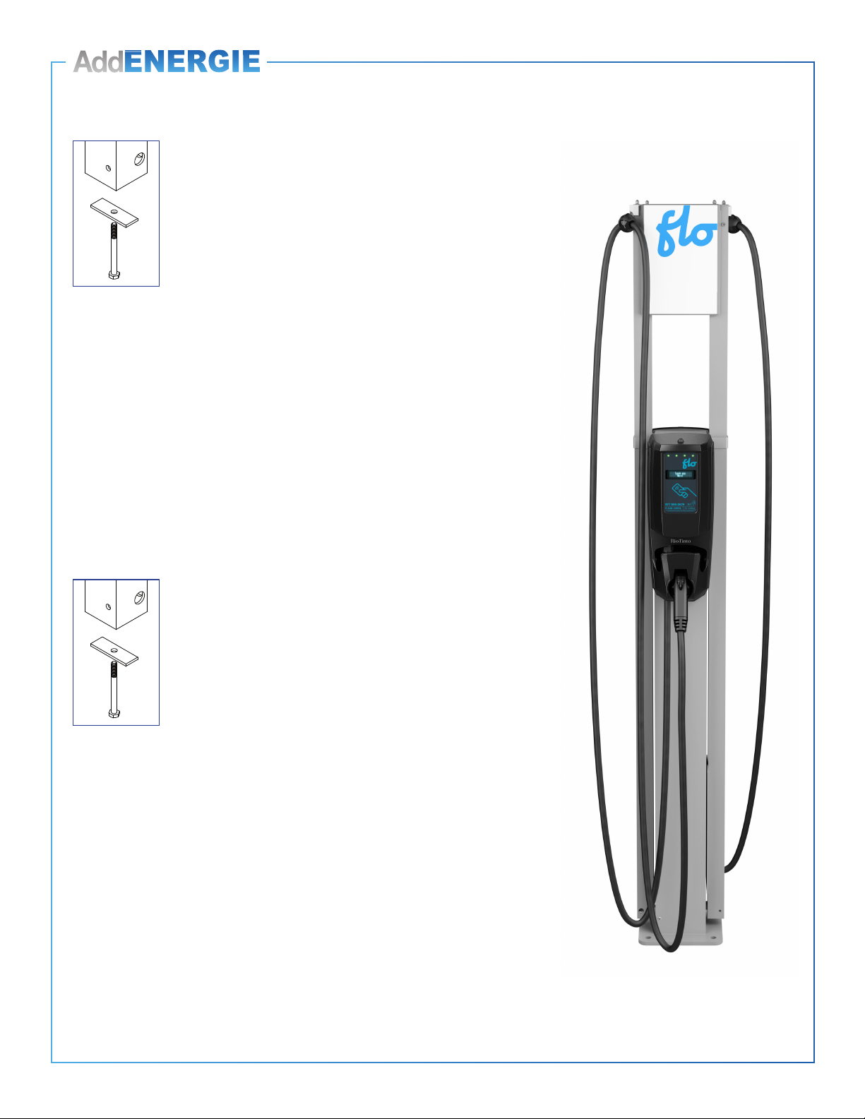
Installation d’une nouvelle borne de recharge et d’un système de rappel.
Installez d’abord la borne de recharge. Reportez-vous au CoRe+ MC Guide d’installation. Installez
ensuite le système de rappel tel qu’il est indiqué ci-après.
¡
Installation d’un système de rappel sur une borne de recharge murale existante.
Installez le système de rappel tel qu’il est indiqué ci-après.
Specic Tools or Material Required
• Wall attachment hardware material (6 mm [¼ in] diameter screw, washers and wall anchors
as required)
BEFORE GETTING STARTED
! When unpackaging the Cable management system, make sure to remove the security screw used
to hold the counterweight during transport.
¡
Installing a new charging station and a Cable management system.
First, install the charging station. Refer to the CoRe+ TM Installation Guide. Then, install the Cable
management system as indicated in the following pages.
¡
Installing a Cable management system on an existing wall mounted charging station.
Install the Cable management system as indicated in the following pages.
Matériel fourni / Included material Qté / Qty
Colonnes murale dotées du système de rappel à cordon rétractable et serre cable / Wall mounted cable
management system columns and cable clamp 1
Support mural inférieur / Lower wall mount bracket 1
Support mural supérieur / Upper wall mount bracket 1
Cales d’espacement / Spacing shims 2
Bande de caoutchouc autocollante 35 mm sur 9,5 mm (6 po sur 13/8 po) / Self-adhesive rubber band
35 mm X 9.5 mm (6 in X 13/8 in) 1
Vis de ¼-20 x 2¾ po, boulon de ¼-20 et rondelle de blocage / ¼-20 x 2¾ screw, ¼-20 bolt and Split lock
washer 1

© 2016 ADDÉNERGIE TECHNOLOGIES INC. TOUS DROITS RÉSERVÉS Les informations et les spécications contenues dans ce document sont sujettes aux changements, modications et ajouts à n’importe quel moment et sans préavis.
© 2016 ADDÉNERGIE TECHNOLOGIES INC. ALL RIGHTS RESERVED Information and specications contained in this document are subject to change, amendments and additions at any time, without notice.
5
V1-2017-09-01
• Déterminez l’emplacement de la colonne murale (colonne). Allouez
de 30 à 35 cm (de 12 à 14 po) entre la colonne et la borne de
recharge.
• Déterminez le matériel de xation requis (ancrages, vis et rondelles)
pour installer solidement les supports au mur. Utilisez des vis de 6
mm (¼ po) de diamètre ainsi que les ancrages de taille appropriée, si
les vis ne sont pas insérées directement dans un montant mural.
Recommandations : Installez la colonne à au moins 15 cm (6 po) du sol
(dégagement sufsant pour faciliter l’entretien du sol). Le support mural
supérieur devrait être installé à environ 152 cm (60 po) au dessus du
support inférieur.
• Determine where the wall mount (column) will be placed. Allow 30 to
35 cm (12 to 14 in) between the column and the charging station.
• Determine what wall attachment hardware is required (wall anchors,
screws and washers) to securely install the mount brackets to the wall.
Use 6 mm (¼ in) diameter screws and anchors of the appropriate size,
if the screws cannot be secured directly in a wall stud.
Recommendations : Install the column at least 15 cm (6 in) from the
ground (allow enough clearance to facilitate oor cleaning). The upper wall
mount bracket should be installed at least 152 cm (60 in) above the lower
wall mount bracket.
152 cm
(60 in)
15 cm
(6 in)
Sol / Floor
Avant de commencer / Before getting started

© 2016 ADDÉNERGIE TECHNOLOGIES INC. TOUS DROITS RÉSERVÉS Les informations et les spécications contenues dans ce document sont sujettes aux changements, modications et ajouts à n’importe quel moment et sans préavis.
© 2016 ADDÉNERGIE TECHNOLOGIES INC. ALL RIGHTS RESERVED Information and specications contained in this document are subject to change, amendments and additions at any time, without notice.
6
V1-2017-09-01
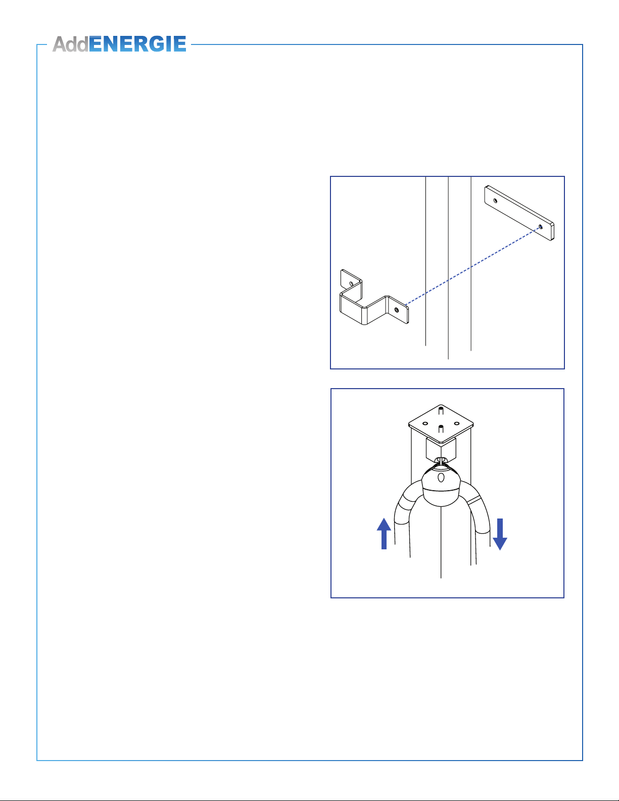
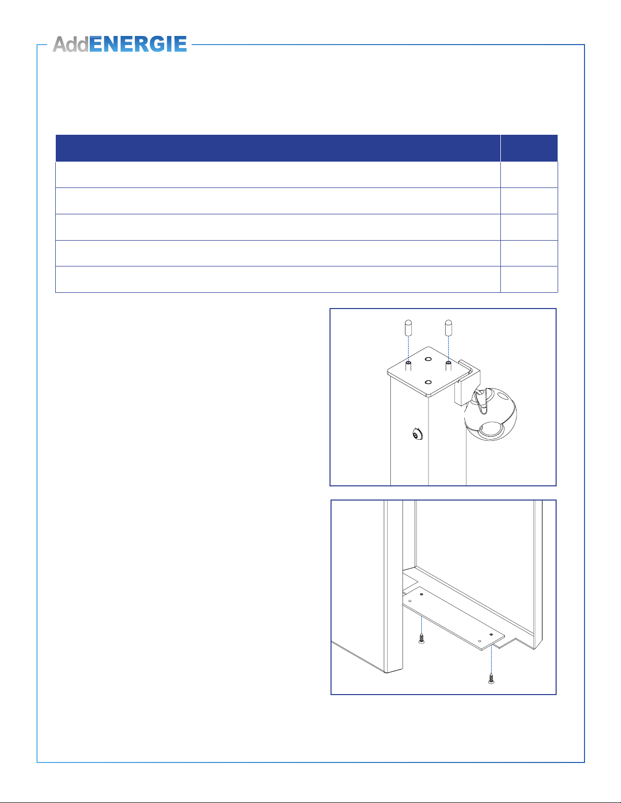
1. Installez d’abord l’une des deux cales d’espacement et
le support mural inférieur à la hauteur désirée à l’aide
de deux vis de 6 mm (¼ po) de diamètre et de deux
rondelles de dimension appropriée. Assurez vous que
les deux pièces soient de niveau horizontalement.
Remarque : Le support mural inférieur se distingue par les
trous qui ont été prépercés en usine.
2. Déposez la colonne dans le support inférieur.
Remarque : Assurez-vous de positionner le serre-câble du
système de rappel du bon côté, soit à droite ou à gauche,
selon la position de la borne de recharge.
3. Fixez la colonne en installant la vis et l’écrou dans le
support mural inférieur à travers le trou prépercé, à
l’aide d’une clé à cliquet et d’une douille à écrou (la vis
de xation est celle qui a servi à retenir le contrepoids).
Installation du système de rappel /
Cable management system installation
1. First, install one of the two spacing shims and the
lower wall mount bracket at the desired height
by using two 6 mm (¼ in) diameter screws and
appropriate washer. Make sure that both brackets are
levelled horizontally.
Remark : The lower wall mount bracket can be identied
by its factory pre-drilled holes.
2. Sit the column in the lower wall mount bracket.
Remark : Make sure to position the Cable management
system’s cable clamp on the correct side, that is on the
right or the left, according to where the charging station is
located.
3. Secure the column by installing the screw and bolt in
the lower wall mount bracket thought the pre drilled
holes with a ratchet wrench and an axel nut socket
(the security screw that was used for holding the
counterweight).
© 2016 ADDÉNERGIE TECHNOLOGIES INC. TOUS DROITS RÉSERVÉS Les informations et les spécications contenues dans ce document sont sujettes aux changements, modications et ajouts à n’importe quel moment et sans préavis.
© 2016 ADDÉNERGIE TECHNOLOGIES INC. ALL RIGHTS RESERVED Information and specications contained in this document are subject to change, amendments and additions at any time, without notice.
7
V1-2017-09-01
Installation du système de rappel /
Cable management system installation
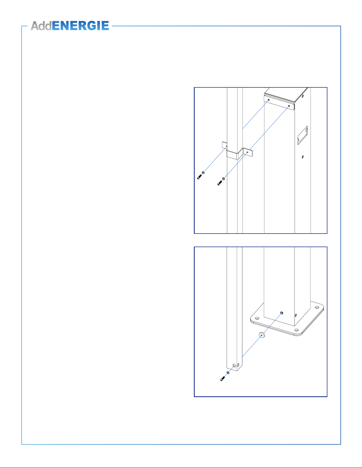
4. Installez le support supérieur et la cale d’espacement
rectangle en y insérant, entre les pièces, la colonne.
Vériez l’angle de la colonne à l’aide du niveau, puis
vissez le tout à l’aide des vis appropriés selon le type
de mur.
5. Vériez l’angle de la colonne à l’aide du niveau.
6. Procédez au positionnement du serre-câble. Reportez-
vous à la page 19.
7. Tirez sur le cordon du système de rappel à quelques
reprises pour veiller à ce que le mécanisme bouge
librement.
4. Install the top bracket and the rectangular spacing
shim while inserting the column between the parts.
Once you ensure that the bracket is ush with the plate
and assembly is level, secure it with the appropriate
screws (according to wall type).
5. Verify the column’s angle with a level.
6. Proceed with the positioning of the cable clamp. Refer
to page 19.
7. Pull on the Cable management system’s cable a few
times to ensure that all parts are moving freely.
© 2016 ADDÉNERGIE TECHNOLOGIES INC. TOUS DROITS RÉSERVÉS Les informations et les spécications contenues dans ce document sont sujettes aux changements, modications et ajouts à n’importe quel moment et sans préavis.
© 2016 ADDÉNERGIE TECHNOLOGIES INC. ALL RIGHTS RESERVED Information and specications contained in this document are subject to change, amendments and additions at any time, without notice.
8
V1-2017-09-01
Installation sur une borne de recharge simple /
Single charging station installation
Matériel fourni / Included material Qté / Qty
Colonnes dotées du système de rappel à cordon rétractable et serre cable / Cable management system
columns and cable clamp 1
Colonne vide / Empty column 1
Support supérieur / Column mount bracket 2
Cales d’espacement rondes / Round spacing shims 2
Cales d’espacement rectangulaire/ Rectangular spacing shims 2
Bande de caoutchouc autocollante / Self-adhesive rubber band 1
Vis de ¼-20 (1’’) (pour piédestal prépercé) / ¼-20 screws (1’’) (for pre-drilled pedestal) 6
Vis autoperceuses (1’’) (pour piédestal non percé) / Self-drilling screws (1’’) (for pedestal with no holes) 6
Gabarit de perçage / Drilling template 1
Gabarit de perçage (pour base) / Drilling template (bottom pedestal)1
SI LE PIÉDESTAL N’EST PAS PRÉ PERCÉ, UTILISEZ LES GABARITS DE PERÇAGES SUIVANT:
IF THE PEDESTAL IS NOT PRE-DRILLED, USE THE FOLLOWING DRILLING TEMPLATES:
Gabarit de perçage supérieur
Top Drilling template
MEC-CST-00280
Gabarit de perçage pour la base
Bottom Drilling template
MEC-CST-00278
© 2016 ADDÉNERGIE TECHNOLOGIES INC. TOUS DROITS RÉSERVÉS Les informations et les spécications contenues dans ce document sont sujettes aux changements, modications et ajouts à n’importe quel moment et sans préavis.
© 2016 ADDÉNERGIE TECHNOLOGIES INC. ALL RIGHTS RESERVED Information and specications contained in this document are subject to change, amendments and additions at any time, without notice.
9
V1-2017-09-01
AVANT DE COMMENCER
! En déballant le système de rappel, assurez-vous de retirer la
vis de xation qui a servi à retenir le contrepoids
durant le transport.
¡
Installation sur une nouvelle borne de recharge simple.
Installez d’abord le piédestal et la borne de recharge. Reportez-
vous au CoRe+ MC Guide d’installation pour piédestal et
CoRe+ MC Guide d’installation respectivement. Installez
ensuite le système de rappel tel qu’il est indiqué ci dessous. Si
le piédestal est prépercé, utilisez les vis ¼-20 fournies dans
l’emballage. Sinon, servez vous du gabarit de perçage et des vis autoperceuses
que vous trouverez avec l’ensemble. Reportez-vous à l’illustration à la page
précédente pour savoir où placer le gabarit sur le piédestal puis marquez les trous
à percer.
¡ Installation sur une borne de recharge simple existante.
Percez les trous qui serviront à accueillir le système de xation du système
de rappel et la colonne vide. Servez vous du gabarit de perçage et des vis
autoperceuses fournis dans l’emballage. Reportez-vous à l’illustration à la page
précédente pour savoir où placer le gabarit sur le piédestal puis marquez les trous
à percer.
BEFORE GETTING STARTED
! When unpackaging the Cable management system, make sure
to remove the security screw used to hold the counterweight
during transport.
¡
Installing on a new single charging station.
First, install the pedestal and the charging station. Refer to
CoRe+ MC Installation Guide for pedestal and CoRe+
MC Installation Guide respectively. Then, install the Cable
management system as indicated below. If the pedestal is
pre-drilled, use the ¼-20 screws provided in the package.
Otherwise, use the drilling template and self-drilling screws also included with the
kit. Refer to the illustration on the former page to know where to place the template
on the pedestal, and mark the holes to drill.
¡ Installing on an existing single charging station.
Drill holes that will be used to install the mount bracket for the column with the
Cable management system and the empty column. Use the drilling template and
the self-drilling screws provided with the kit. Refer to the illustration on the former
page to know where to place the template on the pedestal, and mark the holes to
drill.
© 2016 ADDÉNERGIE TECHNOLOGIES INC. TOUS DROITS RÉSERVÉS Les informations et les spécications contenues dans ce document sont sujettes aux changements, modications et ajouts à n’importe quel moment et sans préavis.
© 2016 ADDÉNERGIE TECHNOLOGIES INC. ALL RIGHTS RESERVED Information and specications contained in this document are subject to change, amendments and additions at any time, without notice.
10
V1-2017-09-01
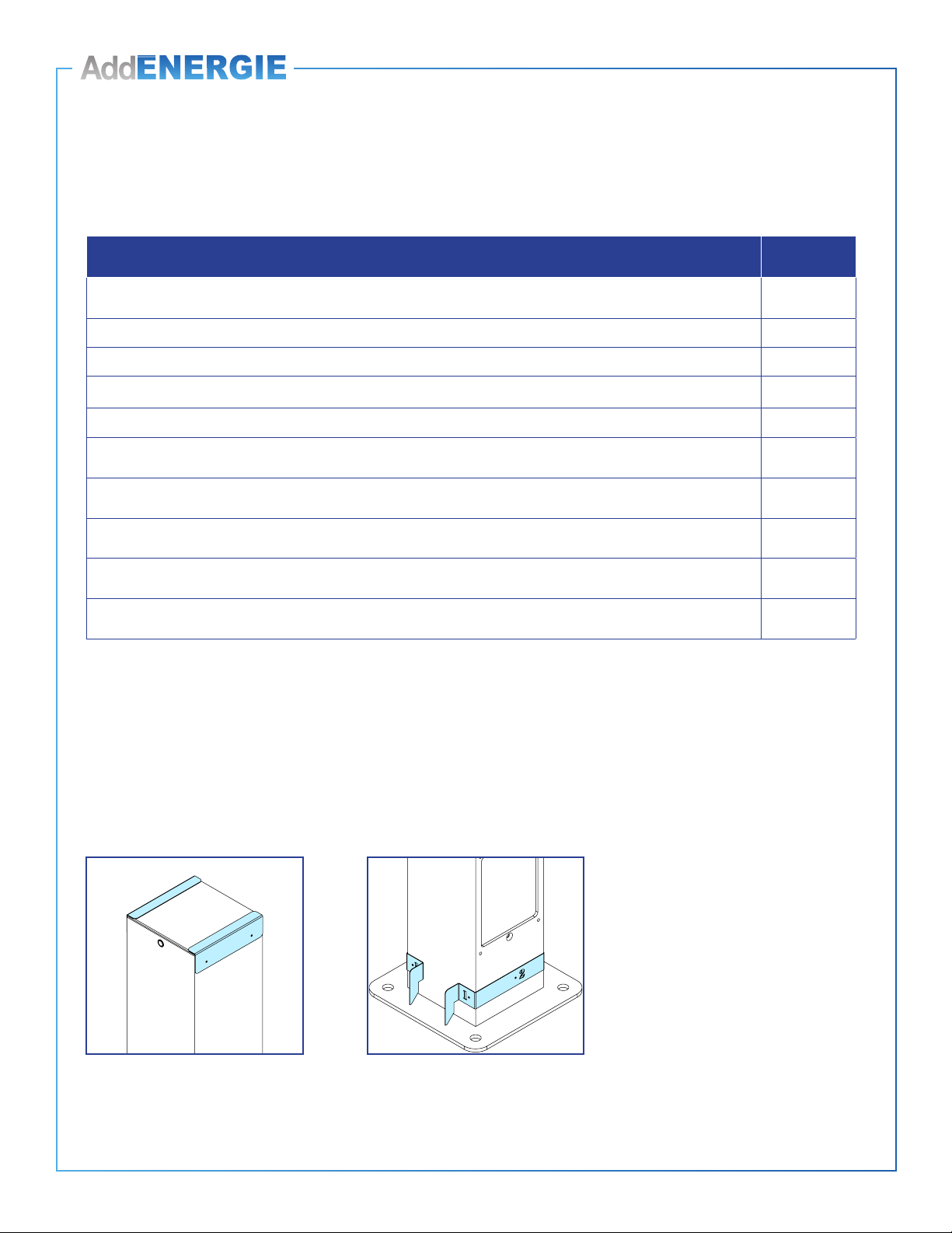
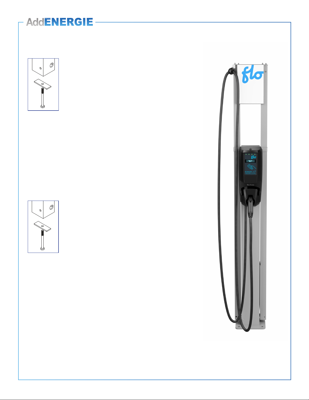
1. Installez d’abord le support supérieur et la cale
d’espacement rectangle en y insérant, entre les deux
pièces, la colonne. Vissez lâchement le tout à l’aide
des vis ¼-20 ou autoperceuses, selon le type de
piédestal, de manière à ce que la colonne du système
de rappel tienne en place et bouge librement pour
installer les pièces de xation inférieures.
Recommandation : En positionnant la colonne, lorsque
vous vous tenez devant la borne de recharge, assurez-vous
de placer la sortie du câble de rappel du côté extérieur.
2. Vissez la colonne du système de rappel en veillant de
mettre la cale d’espacement ronde entre le piédestal
et la colonne puis serrez les vis pour xer solidement la
colonne.
3. Fixer solidement le support supérieur.
4. Posez la colonne vide de l’autre côté de la borne de
recharge en suivant les étapes 1 à 3 ci dessus.
5. Procédez au positionnement du serre-câble. Reportez-
vous à la page 19.
6. Installez l’afche. Reportez-vous à la page 20.
Mise en garde :Ce piédestal est certié comme une boite
électrique et toute modication qui y est apportée doit être
conforme à la règlementation locale.
Installation des systèmes de rappel /
Cable management system installation
1. Install the rectangular spacing shim, place the column
and than install the upper mount bracket on top.
Screw parts loosely with ¼-20 or self-drilling screws,
depending on the type of pedestal you have, so the
Cable management system column is maintained in
place and moves freely to install the lower mounting
hardware.
Recommendation : To position the column, when
standing in front of the charging station, make sure to place
the output of the Cable management on the exterior side.
2. Screw the column of the Cable management system
by placing the round spacing shim (circled in red in the
image included) between the pedestal and the column,
and tighten the screws to solidly secure the column.
3. Secure the top bracket.
4. Install the empty column on the opposite side of the
charging station by following the above steps 1 to 3.
5. Proceed with the positioning of the cable clamp. Refer
to page 19.
6. Install the poster panel. Refer to page 20.
Caution : This pedestal is certied like an electrical
enclosure, and any alteration must comply with local
regulation.

© 2016 ADDÉNERGIE TECHNOLOGIES INC. TOUS DROITS RÉSERVÉS Les informations et les spécications contenues dans ce document sont sujettes aux changements, modications et ajouts à n’importe quel moment et sans préavis.
© 2016 ADDÉNERGIE TECHNOLOGIES INC. ALL RIGHTS RESERVED Information and specications contained in this document are subject to change, amendments and additions at any time, without notice.
11
V1-2017-09-01
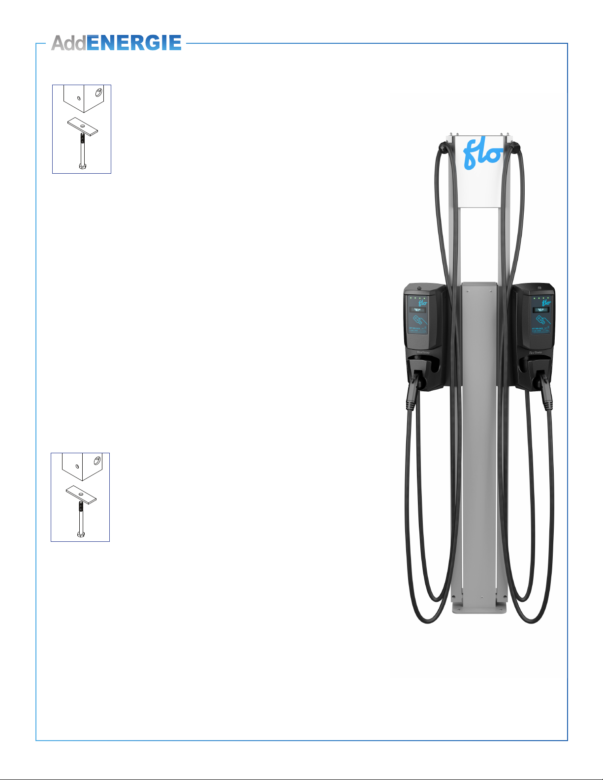
Installation sur deux bornes de recharge dos à dos /
Dual back-to-back charging station installation
Matériel fourni / Included material Qté / Qty
Colonnes dotées du système de rappel à cordon rétractable et serre cable / Cable management system
columns and cable clamp 2
Supports supérieurs / Top mounting brackets 2
Cales d’espacement rondes / Round spacing shims 2
Cales d’espacement rectangles / Rectangular spacing shims 2
Bande de caoutchouc autocollante / Self-adhesive rubber band 2
Vis de ¼-20 (1’’) (pour piédestal prépercé) / ¼-20 screws (1’’) (for pre-drilled pedestal) 6
Vis autoperceuses (1’’) (pour piédestal non percé) / Self-drilling screws (1’’) (for pedestal with no holes) 6
Gabarit de perçage / Drilling template 1
Gabarit de perçage (pour base) / Drilling template (bottom pedestal)1
SI LE PIÉDESTAL N’EST PAS PRÉ PERCÉ, UTILISEZ LES GABARITS DE PERÇAGES SUIVANT:
IF THE PEDESTAL IS NOT PRE-DRILLED, USE THE FOLLOWING DRILLING TEMPLATES:
Gabarit de perçage supérieur
Top Drilling template
MEC-CST-00280
Gabarit de perçage pour la base
Bottom Drilling template
MEC-CST-00278
© 2016 ADDÉNERGIE TECHNOLOGIES INC. TOUS DROITS RÉSERVÉS Les informations et les spécications contenues dans ce document sont sujettes aux changements, modications et ajouts à n’importe quel moment et sans préavis.
© 2016 ADDÉNERGIE TECHNOLOGIES INC. ALL RIGHTS RESERVED Information and specications contained in this document are subject to change, amendments and additions at any time, without notice.
12
V1-2017-09-01
AVANT DE COMMENCER
! En déballant le système de rappel, assurez-vous de retirer la vis
de xation qui a servi à retenir le contrepoids durant le transport.
¡
Installation sur deux nouvelles bornes de recharge
dos à dos.
Installez d’abord le piédestal et des deux bornes de recharge.
Reportez-vous au CoRe+ MC Guide d’installation pour piédestal
et CoRe+ MC Guide d’installation respectivement. Installez
ensuite le système de rappel tel qu’il est indiqué ci dessous. Si le
piédestal est prépercé, utilisez les vis ¼-20 fournies dans l’emballage. Sinon, servez
vous du gabarit de perçage et des vis autoperceuses que vous trouverez avec
l’ensemble. Reportez-vous à l’illustration à la page précédente pour savoir où placer
le gabarit sur le piédestal puis marquez les trous à percer.
¡ Installation sur deux bornes de recharge dos à dos existantes.
Percez les trous qui serviront à accueillir le système de xation des deux systèmes de
rappel. Servez vous du gabarit de perçage et des vis autoperceuses fournies dans
l’emballage.
BEFORE GETTING STARTED
! When unpackaging the Cable management system, make sure to
remove the security screw used to hold the counterweight during
transport.
¡
Installing on new back-to-back dual charging stations.
First, install the pedestal and the two charging stations. Refer
to CoRe+ MC Installation Guide for piedestal and CoRe+ MC
Installation Guide respectively. Then, install the Cable management
system as indicated below. If the pedestal is pre-drilled, use the
¼-20 screws provided in the package. Otherwise, use the drilling template and self-
drilling screws also included with the kit. Refer to the illustration on the former page to
know where to placethe template on the pedestal, and mark the holes to drill.
¡ Installing on existing back-to-back dual charging stations.
Drill holes that will be used to secure the cable management system attachment
hardware. Use the drilling template and the self-drilling screws provided with the kit.

© 2016 ADDÉNERGIE TECHNOLOGIES INC. TOUS DROITS RÉSERVÉS Les informations et les spécications contenues dans ce document sont sujettes aux changements, modications et ajouts à n’importe quel moment et sans préavis.
© 2016 ADDÉNERGIE TECHNOLOGIES INC. ALL RIGHTS RESERVED Information and specications contained in this document are subject to change, amendments and additions at any time, without notice.
13
V1-2017-09-01
Installation des systèmes de rappel /
Cable management system installation
1. Installez d’abord le support supérieur et la cale
d’espacement rectangle en y insérant, entre les deux
pièces, la colonne. Vissez lâchement le tout à l’aide
des vis ¼-20 ou autoperceuses, selon le type de
piédestal, de manière à ce que la colonne du système
de rappel tienne en place et bouge librement pour
installer les pièces de xation inférieures.
Recommandation : En positionnant la colonne, lorsque
vous vous tenez devant la borne de recharge, assurez-vous
de placer la sortie du câble de rappel du côté extérieur.
2. Vissez la colonne du système de rappel en veillant de
mettre la cale d’espacement ronde entre le piédestal
et la colonne puis serrez les vis pour xer solidement la
colonne.
3. Fixer solidement le support supérieur.
4. Posez la colonne vide de l’autre côté de la borne de
recharge en suivant les étapes 1 à 3 ci dessus.
5. Procédez au positionnement du serre-câble. Reportez-
vous à la page 19.
6. Installez l’afche. Reportez-vous à la page 20.
Mise en garde :Ce piédestal est certié comme une boite
électrique et toute modication qui y est apportée doit être
conforme à la règlementation locale.
1. Install the rectangular spacing shim, place the column
and than install the upper mount bracket on top.
Screw parts loosely with ¼-20 or self-drilling screws,
depending on the type of pedestal you have, so the
Cable management system column is maintained in
place and moves freely to install the lower mounting
hardware.
Recommendation : To position the column, when
standing in front of the charging station, make sure to place
the output of the Cable management on the exterior side.
2. Screw the column of the Cable management system
by placing the round spacing shim (circled in red in the
image included) between the pedestal and the column,
and tighten the screws to solidly secure the column.
3. Secure the top bracket.
4. Install the empty column on the opposite side of the
charging station by following the above steps 1 to 3.
5. Proceed with the positioning of the cable clamp. Refer
to page 19.
6. Install the poster panel. Refer to page 20.
Caution : This pedestal is certied like an electrical
enclosure, and any alteration must comply with local
regulation.

© 2016 ADDÉNERGIE TECHNOLOGIES INC. TOUS DROITS RÉSERVÉS Les informations et les spécications contenues dans ce document sont sujettes aux changements, modications et ajouts à n’importe quel moment et sans préavis.
© 2016 ADDÉNERGIE TECHNOLOGIES INC. ALL RIGHTS RESERVED Information and specications contained in this document are subject to change, amendments and additions at any time, without notice.
14
V1-2017-09-01
Installation sur deux bornes de recharge côte à côte /
Dual side-to-side charging station installation
Matériel fourni / Included material Qté / Qty
Colonnes dotées du système de rappel à cordon rétractable et serre cable / Cable management system
columns and cable clamp 2
Cales d’espacement rondes / Round spacing shims 2
Bande de caoutchouc autocollante / Self-adhesive rubber band 2
Vis de ¼-20 (1’’) (pour piédestal prépercé) / ¼-20 screws (1’’) (for pre-drilled pedestal) 6
Vis autoperceuses (1’’) (pour piédestal non percé) / Self-drilling screws (1’’) (for pedestal with no holes) 6
Gabarit de perçage (pour piédestal non percé) / Drilling template (for pedestal with no holes) 1
Supports à bornes (plaque en V) et vis ¼-20 / Charging station mount brackets (V-shape mount) and ¼-20
screws 2
Gaine flexible / Flexible tube 2
Supports à colonne, vis et boulons ¼-20 / Column mount brackets, ¼-20 screws and bolts 4
Couvert arrière et vis / Back cover and screws 2
Gabarit de perçage (pour base) / Drilling template (bottom pedestal) 1
Joint d’étanchéité / Gasket 2
Cales d’espacement rectangles / Rectangular spacing shims 2
SI LE PIÉDESTAL N’EST PAS PRÉ PERCÉ, UTILISEZ LES GABARITS DE PERÇAGES SUIVANT:
IF THE PEDESTAL IS NOT PRE-DRILLED, USE THE FOLLOWING DRILLING TEMPLATES:
Gabarit de perçage supérieur
Top Drilling template
MEC-CST-00280
Gabarit de perçage pour la base
Bottom Drilling template
MEC-CST-00278
© 2016 ADDÉNERGIE TECHNOLOGIES INC. TOUS DROITS RÉSERVÉS Les informations et les spécications contenues dans ce document sont sujettes aux changements, modications et ajouts à n’importe quel moment et sans préavis.
© 2016 ADDÉNERGIE TECHNOLOGIES INC. ALL RIGHTS RESERVED Information and specications contained in this document are subject to change, amendments and additions at any time, without notice.
15
V1-2017-09-01
AVANT DE COMMENCER
! En déballant le système de rappel, assurez-vous de retirer la vis
de xation qui a servi à retenir le contrepoids durant le transport.
¡
Installation de nouvelles bornes de recharge côte à côte
• Installez d’abord le piédestal. Reportez-vous au CoRe+ MC
Guide d’installation pour piédestal.
• Préparez ensuite le matériel d’installation des supports à
borne de recharge côte à côte et des systèmes de rappel, et
suivez les instructions qui sont présentées ci-dessous.
• Installez enn les bornes à recharge. Reportez-vous au CoRe+ MC Guide
d’installation.
• Installation sur des bornes de recharge côte à côte existantes
Mise en garde : Avant de commencer, interrompez le courant pour éviter toute
décharge électrique.
INSTALLATION SUR DES BORNES DE RECHARGE EXISTANTES
1. Désinstallez les deux bornes de recharge du piédestal an d’être en mesure
de poser les nouveaux supports à borne de recharge côte à côte et les deux
systèmes de rappel.
2. Défaites le câblage puisqu’il vous faudra brancher les bornes à de nouveaux ls
électriques.
3. Préparez ensuite le matériel d’installation des supports à borne de recharge côte
à côte et le système de rappel et suivez les instructions qui sont présentées ci-
dessous.
4. Réinstallez les bornes de recharge sur les nouveaux supports.
Prévoyez du 30 cm (10 po) de câblage électrique supplémentaire an de
pouvoir raccorder la borne de recharge dans sa nouvelle installation.
BEFORE GETTING STARTED
! When unpackaging the Cable management system, make sure to
remove the security screw used to hold the counterweight during
transport.
¡
Installing new side-by-side charging stations
• First, install the pedestal. Refer to CoRe+ MC Installation
Guide for pedestal.
• Then, prepare installation material for the side-by-side
charging station mount brackets and Cable management
systems, and follow the instructions that are indicated below.
• Finally, install the charging stations. Refer to CoRe+ MC Installation Guide.
• Installing on existing side-by-side charging stations
Caution : Before getting started, cut off the current to prevent an electric shock.
INSTALLATION ON PRE-INSTALLED CHARGING STATIONS
1. Remove both charging stations from the pedestal so that you can install the new
side-by-side charging station mount brackets and the two Cable management
systems.
2. Remove the wiring as you will need to hook the charging stations to new wires.
3. Then, prepare installation material for the side-by-side charging station mount
brackets and Cable management systems, and follow the instructions that are
indicated below.
4. Reinstall the charging station on the new brackets.
Allow 10 «(30 cm) of additional electrical wiring to connect the new charging
station to the installation.

© 2016 ADDÉNERGIE TECHNOLOGIES INC. TOUS DROITS RÉSERVÉS Les informations et les spécications contenues dans ce document sont sujettes aux changements, modications et ajouts à n’importe quel moment et sans préavis.
© 2016 ADDÉNERGIE TECHNOLOGIES INC. ALL RIGHTS RESERVED Information and specications contained in this document are subject to change, amendments and additions at any time, without notice.
16
V1-2017-09-01
1. Assemblez la gaine exible.
2. Retirez la plaque d’accès au câblage électrique au bas
du piédestal et prévoyez 30 cm (10 po) de l excédentaire
an d’y brancher la borne une fois que la gaine exible
aura été posée.
3. Vissez le bout de la gaine exible au support à borne de
recharge, du côté du piédestal.
4. Passez les ls dans la gaine exible.
5. Vissez le premier support à borne de recharge au
piédestal* dans les trous qui sont prévus à cet effet à
l’aide des vis fournies, soit les trous ayant servi à visser
les bornes de recharge installées dos à dos auparavant.
Mise en garde :Ce piédestal est certié comme une boite
électrique et toute modication qui y est apportée doit être
conforme à la règlementation locale.
6. Placez la colonne du système de rappel à l’intérieur du
support à borne de recharge, bien appuyée dans le coin.
Recommandation : En positionnant la colonne, lorsque vous
vous tenez devant la borne de recharge, assurez-vous de
placer le serre-câble du système de rappel du côté extérieur
et qu’il y as un joint d’étanchéité installé entre couverts arrière
et le piédestal.
Installation des supports à borne de recharge côte à côte et des systèmes de rappel /
Side-to-side charging station supports and cable management systems installation
1. Assemble the exible tube.
2. Remove the plate giving you access to the electric wires
at the bottom of the pedestal and allow 30 cm (10 in) of
extra wiring so to connect the charging station once the
exible tube has been installed.
3. Screw the end of the exible tube to the charging station
mount bracket, on the pedestal side.
4. Pass wires through the exible tube.
5. Screw the rst charging station mount bracket to the
pedestal* using the holes provided for this purpose with
the included screws, that is, the holes that were used to
secure the charging stations that were installed back-to-
back previously.
Caution : This pedestal is certied like an electrical enclosure,
and any alteration must comply with local regulation.
6. Place the column of the Cable management system
inside the charging station mount bracket, place tightly in
the corner.
Recommendation : To position the column, when you
stand in front of the charging station, make sure to place the
output (cable clamp) of the Cable management system on the
exterior side, and a gasket is inserted between the pedestal
and the back cover.
© 2016 ADDÉNERGIE TECHNOLOGIES INC. TOUS DROITS RÉSERVÉS Les informations et les spécications contenues dans ce document sont sujettes aux changements, modications et ajouts à n’importe quel moment et sans préavis.
© 2016 ADDÉNERGIE TECHNOLOGIES INC. ALL RIGHTS RESERVED Information and specications contained in this document are subject to change, amendments and additions at any time, without notice.
17
V1-2017-09-01
7. Vissez le bas de la colonne du système de rappel en
vous assurant de mettre la cale d’espacement ronde
entre le piédestal et la colonne puis serrez les vis pour
xer solidement la colonne.
8. Insérez l’autre bout de la gaine exible dans le trou qui
est prévu à cet effet puis vissez la bague à l’extérieur
du support à borne de recharge de manière à
maintenir la gaine exible bien en place.
Remarque : Cette mesure permettra de retenir la colonne
le temps de visser le bas de la colonne.
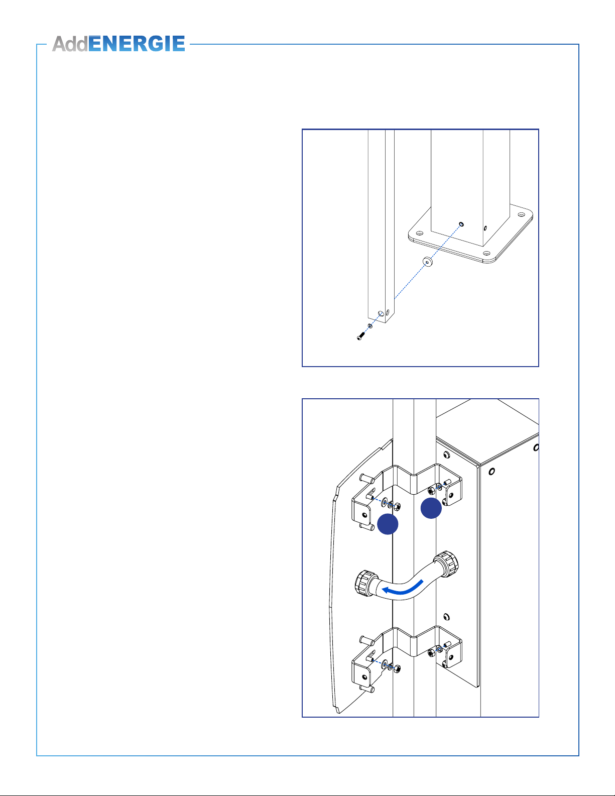
9. Installez les deux supports à colonnes, en
commençant par installer le 1er côté (1 sur illustration)
et ensuite le second (2 sur illustration).
Remarques : Chaque support comporte une fente pour
faciliter son installation. Celle-ci doit être placée sur la partie
frontale du support, c’est-à-dire du côté où sera installée
la borne de recharge. Ne serrez pas trop les boulons au
moment de placer les supports pour les bouger facilement
et les positionner correctement. Une fois la pièce bien en
place, serrez les boulons.
7. Screw the bottom column of the Cable management
system by placing the round spacing shim between the
pedestal and the column, and tighten the screws solidly
to secure the column.
8. Insert the other end of the exible tube in the hole
provided for this purpose , and screw the bushing from
the exterior of the charging station mount bracket so to
maintain the exible tube in place.
Remark : This will allow to hold the column during the
installation of the bottom column mount brackets.
9. Install both column mount brackets starting with the 1st
assembly (1 on illustration) then proceed installing the 2nd
(2 on illustration).
Remarks : Each column mount bracket has a slot to make
its installation easier, which must be place on the front side
of the bracket, in other words on the side where the charging
station will be installed. Do not screws the bolts too tight
when placing the brackets so you can move them easily and
position them correctly. Once everything is well positioned,
Installation des supports à borne de recharge côte à côte et des systèmes de rappel /
Side-to-side charging station supports and cable management systems installation
1
2
© 2016 ADDÉNERGIE TECHNOLOGIES INC. TOUS DROITS RÉSERVÉS Les informations et les spécications contenues dans ce document sont sujettes aux changements, modications et ajouts à n’importe quel moment et sans préavis.
© 2016 ADDÉNERGIE TECHNOLOGIES INC. ALL RIGHTS RESERVED Information and specications contained in this document are subject to change, amendments and additions at any time, without notice.
18
V1-2017-09-01
Installation des supports à borne de recharge côte à côte et des deux systèmes de rappel /
Side-to-side charging station supports and cable management installation
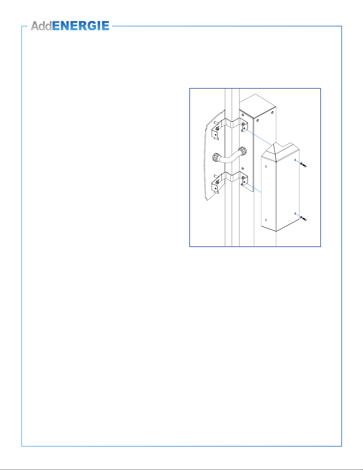
10. Vissez le couvert arrière dans les supports à colonne à
l’aide des quatre vis.
11. Installez la deuxième colonne du côté opposé en suivant
les étapes 1 à 10 qui sont décrites ci dessus.
12. Réinstallez ou réinstallez la borne de recharge. Reportez-
vous au CoRe+ MC Guide d’installation au besoin.
13. Procédez au positionnement du serre-câble. Reportez-
vous à la page 19.
14. Installez l’afche. Reportez-vous à la page 20.
tighten the bolts.
10. Secure the back cover in the column mount brackets with
the four screws.
11. Install the second column on the opposite side of the
charging station by following the above steps 1 to 10.
12. Install or reinstall the charging stations. Refer to the
CoRe+ MC Installation Guide if need be.
13. Proceed with the positioning of the cable clamp. Refer to
page 19.
14. Install the poster panel. Refer to page 20.

© 2016 ADDÉNERGIE TECHNOLOGIES INC. TOUS DROITS RÉSERVÉS Les informations et les spécications contenues dans ce document sont sujettes aux changements, modications et ajouts à n’importe quel moment et sans préavis.
© 2016 ADDÉNERGIE TECHNOLOGIES INC. ALL RIGHTS RESERVED Information and specications contained in this document are subject to change, amendments and additions at any time, without notice.
19
V1-2017-09-01
Positionnement du serre-câble /
Positioning the cable clamp
1. Tirez sur le cordon du système de rappel pour tenir le
serre-câble dans votre main.
2. Retirez les vis Torx.
3. Déterminez l’emplacement du serre-câble sur le câble de
la borne de recharge.
Recommandation : La portion du câble entre le serre-
câble et le connecteur de recharge ne doit pas toucher le sol
lorsque le cordon du système de rappel est complètement
rétracté. Placez le serre-câble de manière à ce que le câble
soit suspendu à environ 5 cm (2,5 po) du sol.
4. Enroulez solidement la bande de caoutchouc autocollante
autour du câble an de protéger celui-ci. Revissez le
serre-câble sur la bande de caoutchouc en ajustant
la couple de votre outil à 7 po-lb.
5. Laissez le cordon se rétracter. Vériez le dégagement
entre le câble de la borne de recharge et le sol.
6. Enroulez l’excédent de câble autour de l’enrouleur de la
borne de recharge.
1. Pull on the cable of the Cable management system to
hold the cable clamp in your hand.
2. Remove Torx screws.
3. Determine where to position the charging station cable
clamp.
Recommendation : The cable portion between the clamp
and the charging connector must not touch the ground when
the Cable management system is completely retracted. The
cable should hang about 5 cm (2.5 in) above the ground.
4. Apply the self-adhesive rubber band around the cable for
protection purposes. Set the clamp over the band and
reinsert the screws in it by adjusting the torque of
your tool to 7 in-lb.
5. Let the cable retract itself. Verify the clearing between the
charging station cable and the ground.
6. Roll the cable overhang around the charging station cable
holder.
© 2016 ADDÉNERGIE TECHNOLOGIES INC. TOUS DROITS RÉSERVÉS Les informations et les spécications contenues dans ce document sont sujettes aux changements, modications et ajouts à n’importe quel moment et sans préavis.
© 2016 ADDÉNERGIE TECHNOLOGIES INC. ALL RIGHTS RESERVED Information and specications contained in this document are subject to change, amendments and additions at any time, without notice.
20
V1-2017-09-01
Installation de l’afche /
Positioning the poster panel
1. Le dessus des colonnes est doté de vis intégrées sur
lesquelles sont xés des capuchons de caoutchouc et
des rondelle. Retirez ceux-ci et les gardez.
2. L’afche comporte deux panneaux. Avant de l’installer,
vissez la plaque de xation à la base d’un des panneaux
à l’aide des vis qui sont prévues à cet effet. La plaque
est placée à l’intérieur du panneau. Insérez les vis de
l’extérieur du panneau vers l’intérieur.
1. The top of the columns has embedded screws with
rubber caps and washers attached to them. Remove
them and set aside.
2. The poster panel is comprised of two parts. Before
installing it, secure the attachment plate to the base of
one of the panels with the screws provided. The plate
is placed inside the panel, and the screws are inserted
inwards.
Matériel fourni / Included material Qté / Qty
Affiche (comprenant deux panneaux) / Poster panel (including two sides) 2
Plaque de fixation et vis / Attachment plate and screws 1
Boulons / Bolts 4
Rondelles / Washers 4
Rondelle de blocage / Split lock washer 4
Other manuals for CoRe+
1
This manual suits for next models
2
Table of contents


