manuals.online logo
Brands
  1. Home
  2. •
  3. Brands
  4. •
  5. Tyco Electronics
  6. •
  7. Cables And Connectors
  8. •
  9. Tyco Electronics AMP User manual

Tyco Electronics AMP User manual

Instruction Sheet
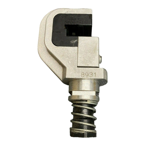
Terminating Head 58063–2
For AMPLIMITE* High Density (HDE)–20 408–9414
LOC B
1 of 4
E
2004 Tyco Electronics Corporation, Harrisburg, PA
AllInternationalRightsReserved
AMP and Tyco are trademarks. *Trademark
Other products, logos, and company names used are the property of their respective owners.
TOOLINGASSISTANCE CENTER1–800–722–1111
FAX/PRODUCTINFO1–800–522–6752
For Regional Customer Service, visit our website at
www.tycoelectronics.com
This controlled document is subject to change.
For latest revision, call the FAX/PRODUCT INFO number.
12 JUL 04 Rev A
Connectors
Figure 1
FeedChannel
WireInserter
Adjuster
(InserterRod)
Anti–Backup
Pawl
FeedSlide
WireGuide
1. INTRODUCTION
Terminating Head 58063–2 is designed to terminate
unstripped
discrete wire sizes 30 through 20 AWG
onto AMPLIMITE HDE–20 all plastic connectors
(reference part number 745203–2) and metal shell
connectors (reference part number 745492–2). These
connectors contain insulation displacement contacts.
The head must be used with one of the following
power units (for operating procedure, refer to the
instructions packaged with the power unit).
Power Unit Instruction Sheet (408) or
Customer Manual (409)
Pistol Grip Manual Handle
Assembly 58074–1 408–6790
Pistol Grip Pneumatic Handle
Assembly 58075–1 408–6789
Pneumatic Power Bench
Assembly 58338–1 408–9393
Electric Power Unit 931800–1 409–5746
Dimensions in this instruction sheet are in metric
units [with U.S. customary units in brackets].
Figures are not drawn to scale.
Reasons for reissue of this instruction sheet are
provided in Section 7, REVISION SUMMARY.
2. DESCRIPTION (Figure 1)
Features of the head and their function are as follows:
Wire inserter—forces the wire into the slotted beams
of the contact.
Wire guide—holds the connector properly in relation
to the wire.
Adjuster (inserter rod)—is a piston for, and regulates
the travel of, the wire inserter.
Feed slide—automatically advances the connector
after each termination.
Anti–backup pawl—prevents the connector from
moving out of position after it has been advanced by
the feed slide.
After the head is installed onto the power unit, it
serves as a guide and support for the connector
during termination. The arrow on the top of the head
indicates the direction that the connector will move in
the head. The wires are terminated onto the
connector using the insulation displacement
technique.
3. TERMINATION PROCEDURE
Make sure that the connector matches the wire size
to be terminated, then refer to Figure 2, and proceed
as follows:
1. Align the side of the connector with the side of
the head (so that it will move in the direction of the
arrow), and
slowly
slide the connector into the feed
channel. Stop when the desired contact position
aligns with the wire slot.
If the connector cannot be inserted into the head
or if the connector is too loose in the head, refer
to Paragraph 4.2 for wire guide adjustment.
2. Insert the wire into the wire slot until the wire
bottoms on the head.
3. Center the wire in the wire slot, then actuate the
power unit until the wire inserter bottoms (the wire
inserter will retract, and the connector will advance
to the next contact position).
NOTE
NOTE
408–9414
Terminating Head 58063–2
Rev A2 of 4
Figure 2
Wire Wire
Slot
SlideConnector
IntoFeed Channel
PowerUnit
(Ref)
Connector
TerminatingConnector
4. Repeat Steps 2 and 3 until all applicable
contacts are terminated.
5. Slide the connector out of the head in the
direction of the arrow.
6. Inspect each terminated contact according to
Figure 4. If any contact does not meet the
requirements, DO NOT use the connector. Refer to
Section 4 for adjustments.
For application requirements for the connectors,
refer to application specification 114–40002.
For assembly procedure, refer to 408–6621 for
all plastic connectors and 408–6645 for metal
shellconnectors.
4. ADJUSTMENTS
4.1. Wire Insertion Depth
If the wire is inserted too deep or not deep enough in
the contact after termination, adjust the wire insertion
depth as follows:
A. Pneumatic Power Units
To avoid personal injury when using pneumatic
power units, ALWAYS disconnect the air supply
beforemaking any adjustments.
Increase the air pressure by 10 psi [69 kPa]. Repeat
the termination and inspection procedure. Continue in
this manner until the proper wire insertion depth is
obtained or the air pressure is set to 70 psi [483 kPa].
If proper wire insertion depth is not obtained at 70 psi
[483 kPa], return the air pressure to 40 psi [276 kPa]
and follow Paragraph B.
For pneumatic power units, it might be necessary
to adjust either the air pressure or the adjuster
(inserterrod).
B. Manual and Electric Power Units
To prevent personal injury when using electric
power units, ALWAYS disconnect the electrical
power supply before making any adjustments.
1. Remove the head from the power unit according
to the instructions packaged with the power unit.
Make sure to observe any cautions and dangers.
2. Turn the adjuster (inserter rod) one–sixth of a
revolution
clockwise
if the wire is too deep in the
contact, and
counterclockwise
if the wire is not
deep enough in the contact. Refer to Figure 3. This
will decrease or increase the wire insertion depth
by approximately 0.20 mm [.008 in.].
3. Install the head onto the power unit according to
the instructions packaged with the power unit.
Make sure to observe any cautions and dangers.
Figure 3
TurnCLOCKWISE
ToDecrease
Wire Insertion Depth
TurnCOUNTERCLOCKWISE
ToIncrease
Wire Insertion Depth Adjuster
(InserterRod)
Wire Insertion Depth Adjustment
4.2. Wire Guide
If the connector cannot be inserted into the head, the
connector is too loose in the head, or the connector
housing is damaged after termination, refer to Figure
1, and adjust the wire guide as follows:
1. For pneumatic power units, disconnect the air
supply. For electric power units, disconnect the
electrical power supply.
2. Loosen the two screws on the wire guide.
3. Slide the wire guide until the connector fits
properly in the head.
4. Finger–tighten the screws.
5. INSPECTION AND MAINTENANCE
5.1. Inspection
Regular inspections should be performed by quality
control personnel with a record of quality control
inspections remaining with the personnel responsible
for the head. One inspection per month is the
NOTE
DANGER
NOTE
DANGER
408–9414
Terminating Head 58063–2
3of 4Rev A
Figure 4
Centerlineof
Conductor
Correct Acceptable
T
erminationInspection
Incorrect
Wire Was Not Inserted
DeepEnough During
Termination
Wire Was Not Inserted
StraightBefore
Termination
Wire Was Not Fully
InsertedBefore
Termination
Wire Was Inserted With
Too Much Force During
Termination
DamagedHousing—
Connector Was Too
Tight or Too Loose in
Head During Termination
A
A
0.84+0.10 mm
[.033+.004 in.]
SectionA–A
Arms of Insulation Support
BarrelPartially Closed
Arms of Insulation Support
BarrelCompletelyClosed
AMPLIMITEHDE–20
ReceptacleConnector
0.51 mm
[.020in.]
Min
recommended frequency; however, operator training
and skill, amount of use, working conditions, and
established company standards are all factors to be
considered in establishing inspection frequency.
5.2. Daily Maintenance
1. Remove dust, moisture, and other contaminants
with a clean, soft brush or lint–free cloth. DO NOT
use objects that could damage the head.
2. Make sure that all components are in place and
properly secured.
3. Make sure that the mechanisms inside the head
function smoothly.
5.3. Periodic Maintenance
1. Remove any accumulated film with a suitable
cleaning agent that will not affect plastic.
2. Check for chipped, cracked, worn, or broken
areas on the head. If damage is evident, repair or
replace the head.
6. REPLACEMENT AND REPAIR
Customer–replaceable parts are listed in Figure 5.
A complete inventory should be stocked and
controlled to prevent lost time when replacement of
parts is necessary. Parts other than those listed
should be replaced by Tyco Electronics to ensure
quality and reliability. Order replacement parts
through your representative, or call 1–800–526–5142,
or send a facsimile of your purchase order to
717–986–7605, or write to:
CUSTOMER SERVICE (038–035)
TYCO ELECTRONICS CORPORATION
PO BOX 3608
HARRISBURG PA 17105–3608
For customer repair service, call 1–800–526–5136.
408–9414
Terminating Head 58063–2
Rev A4 of 4
1
2
3
15
67 9
5
13
10
12 11
8
A A
SectionA–A
84.07 mm [3.31 in.]
25.4 mm
[1.0 in.]
44.45mm
[1.75in.]
144
REPLACEMENT PARTS
ITEM PART NUMBER DESCRIPTION QTY PER HEAD
1 312331–1 HEAD 1
2 28593–1 SCREW, Self–Tapping 2
3 314011–1 HOUSING, Insert 1
4 314012–1 PAWL 1
5 1–23147–2 SPRING, Compression 2
6 312339–1 INSERTER, Wire 1
7 312340–1 GUIDE, Wire 1
8 4–23715–7 SCREW, Machine, 4–40

.750 in. L 2
9 3–21028–2 PIN, Slotted Spring 1
10 312149–1 ADJUSTER (Inserter Rod) 1
11 22488–5 SPRING, Compression 1
12 312148–2 ROD, Inserter 1
13 314013–1 SLIDE, Feed 1
14 304580–0 PIN, Spirol 1
15 314014–1 PAWL, Locator 1
Figure 5
7. REVISION SUMMARY
Revisions to this instruction sheet per EC
0990–0902–04 include:
S
Updated document to corporate requirements
S
Added electric power unit to Section 1
S
Replaced Figures 2 and 3 with reference
connector part numbers
S
Removed instruction for feed adjustment
S
Removed Item 3 from Figure 5

Other Tyco Electronics Cables And Connectors manuals

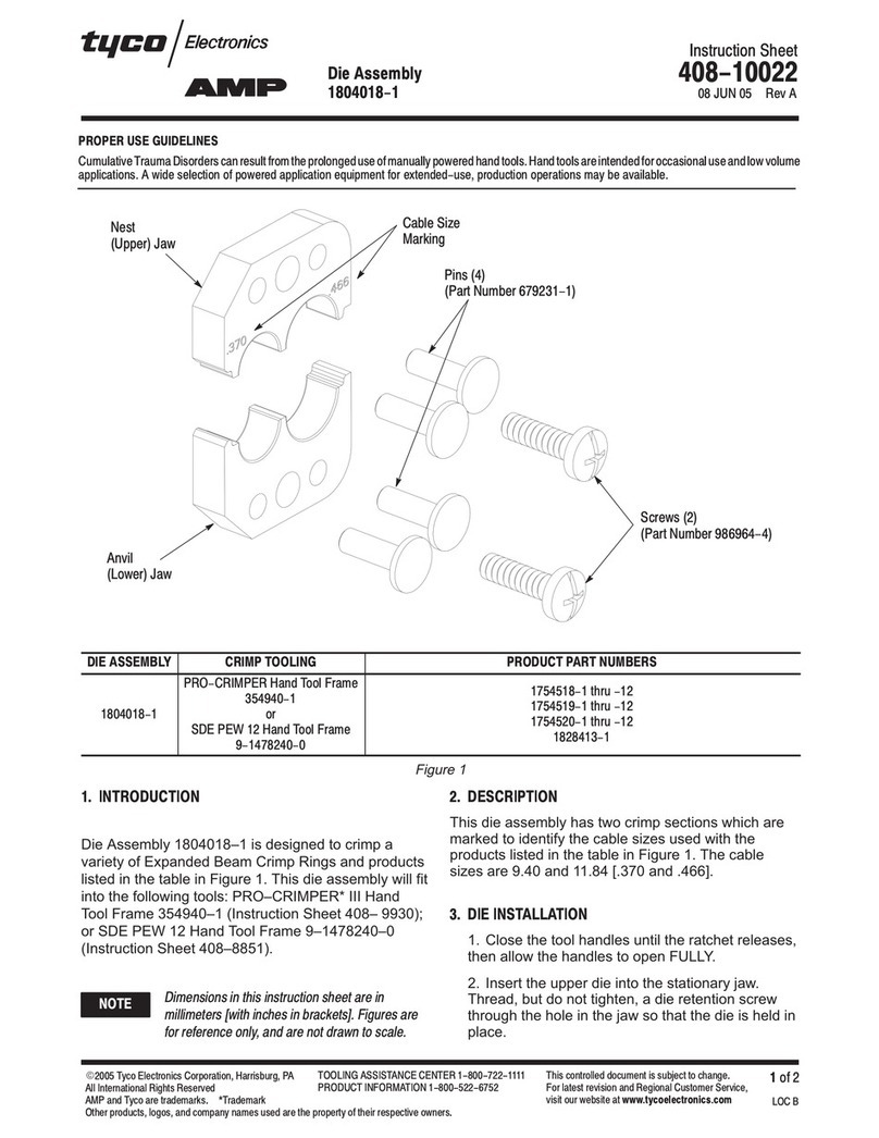
Tyco Electronics AMP 1804018-1 Assembly instructions

Tyco Electronics

Tyco Electronics AMP 1804018-1 Assembly instructions

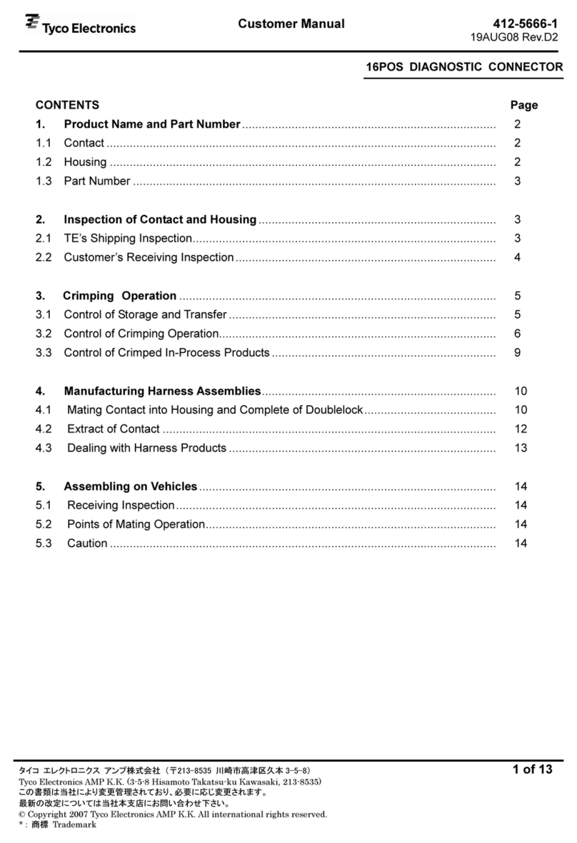
Tyco Electronics 16Pos.Plug Housing Reference guide

Tyco Electronics

Tyco Electronics 16Pos.Plug Housing Reference guide

Tyco Electronics D2950 User manual

Tyco Electronics

Tyco Electronics D2950 User manual

Tyco Electronics RECORDsplice User manual

Tyco Electronics

Tyco Electronics RECORDsplice User manual

Tyco Electronics SOLARLOK 4-1394462-6 User manual

Tyco Electronics

Tyco Electronics SOLARLOK 4-1394462-6 User manual

Tyco Electronics AMP NETCONNECT AMPTRAC User manual

Tyco Electronics

Tyco Electronics AMP NETCONNECT AMPTRAC User manual

Tyco Electronics CPC 45 Series User manual

Tyco Electronics

Tyco Electronics CPC 45 Series User manual

Tyco Electronics AMP NETCONNECT MRJ21 User manual

Tyco Electronics

Tyco Electronics AMP NETCONNECT MRJ21 User manual

Tyco Electronics ACO Single Port Kits User manual

Tyco Electronics

Tyco Electronics ACO Single Port Kits User manual

Tyco Electronics Raychem C25-21 User manual

Tyco Electronics

Tyco Electronics Raychem C25-21 User manual

Tyco Electronics GPRA1 User manual

Tyco Electronics

Tyco Electronics GPRA1 User manual

Tyco Electronics LightCrimp Plus ST User manual

Tyco Electronics

Tyco Electronics LightCrimp Plus ST User manual

Tyco Electronics LightCrimp Plus LC User manual

Tyco Electronics

Tyco Electronics LightCrimp Plus LC User manual

Tyco Electronics Raychem HVS-T-1580E-S Series User manual

Tyco Electronics

Tyco Electronics Raychem HVS-T-1580E-S Series User manual

Tyco Electronics 1-1718624-1 User manual

Tyco Electronics

Tyco Electronics 1-1718624-1 User manual

Tyco Electronics 408-10254 User manual

Tyco Electronics

Tyco Electronics 408-10254 User manual

Tyco Electronics AMP NETCONNECT MRJ21 User manual

Tyco Electronics

Tyco Electronics AMP NETCONNECT MRJ21 User manual

Tyco Electronics 58449-1 User manual

Tyco Electronics

Tyco Electronics 58449-1 User manual

Tyco Electronics 1362990-1 User manual

Tyco Electronics

Tyco Electronics 1362990-1 User manual

Tyco Electronics LightCrimp Plus LC User manual

Tyco Electronics

Tyco Electronics LightCrimp Plus LC User manual

Tyco Electronics 58062-1 User manual

Tyco Electronics

Tyco Electronics 58062-1 User manual

Tyco Electronics AMP Series User manual

Tyco Electronics

Tyco Electronics AMP Series User manual

Popular Cables And Connectors manuals by other brands

Philips SWV3032S/10 user manual

Philips

Philips SWV3032S/10 user manual

National Instruments NI-XNET CAN HS/FD operating instructions

National Instruments

National Instruments NI-XNET CAN HS/FD operating instructions

Manhattan 205146 instructions

Manhattan

Manhattan 205146 instructions

TP-Link TL-POE10R user guide

TP-Link

TP-Link TL-POE10R user guide

Energenie DSP-DVI-21 user manual

Energenie

Energenie DSP-DVI-21 user manual

SALTEK HX-090 SMA F/M Installation instruction

SALTEK

SALTEK HX-090 SMA F/M Installation instruction

Festo NEBM-M12G8-E S1G9-V4 Series Assembly instructions

Festo

Festo NEBM-M12G8-E S1G9-V4 Series Assembly instructions

Philips SWV3472S/10 user manual

Philips

Philips SWV3472S/10 user manual

VPC ICON user manual

VPC

VPC ICON user manual

Philips SWV4000S/10 user manual

Philips

Philips SWV4000S/10 user manual

Vanco 280902 product manual

Vanco

Vanco 280902 product manual

Thermon Terminator ZP-XP Installation procedures

Thermon

Thermon Terminator ZP-XP Installation procedures

RTI VDA-12 user manual

RTI

RTI VDA-12 user manual

Gefen TOOLBOX GTB-HD4K2K-148C-BLK user manual

Gefen TOOLBOX

Gefen TOOLBOX GTB-HD4K2K-148C-BLK user manual

Tripp Lite N818-02M Specification sheet

Tripp Lite

Tripp Lite N818-02M Specification sheet

Techno TH384 quick start guide

Techno

Techno TH384 quick start guide

Belden FiberExpress Brilliance installation instructions

Belden

Belden FiberExpress Brilliance installation instructions

Staubli PV-KST4-UR Series Assembly instructions

Staubli

Staubli PV-KST4-UR Series Assembly instructions

manuals.online logo
manuals.online logoBrands
  • About & Mission
  • Contact us
  • Privacy Policy
  • Terms and Conditions

Copyright 2025 Manuals.Online. All Rights Reserved.