Addie Water Systems IRON GENIE1 User manual

IRON GENIE
Chemical Free Iron & Sulfur Reduction

SPECIFICATIONS
MODEL # TANK SIZE
MEDIA
CUBIC FEET
SERVICE *
FLOW RATE
(GPM)
PEAK*
FLOW RATE
(GPM)
BACKWASH RATE
(GPM)
TIG56SXT-SI 10X54 1.0 2.5 3.7 7.0
TIG56SXT-SI-ECM 13X54 2.0 4.5 7.0 11.0
*Peak flow rates are non-continuous for residential use only. Flow rates are substantially higher when ZeoPrep filtering media is used.

Iron Gen e Operat ng & Serv ce Manual
The Iron Genie is an excellent ay to remove iron and sulfur from your ater.
Based on a unique patent-protected (US Patent 5,919,373) process the Iron
Genie removes iron effectively and economically ithout the need for costly
dangerous chemicals, troublesome pumps, or external air injectors.
The Iron Genie can be used henever iron is a problem. Years of field
experience ith the Iron Genie have sho n it ill remove iron in excess of 10
parts per million (PPM) and remain effective in high PH ater.
How Does It Work?
The Iron Genie adds oxygen to the incoming ra ater by passing the ater
through a pressurized air head in the media tank. This ill begin to convert
dissolved elements such as iron or manganese to a physical particle or non-soluble
precipitate. The particles are then captured in the filter media.
Eventually ater passing through the Iron Genie depletes the oxygen and the unit
needs regeneration.
During regeneration process the iron is back ashed out of the filter media and
the oxygen is replenished from atmosphere and then shifts back into service.
INSTALLATION
The Iron Genie ill normally be installed:
After: Supply line to outside faucets
Any Neutralizers
Before: A Water Softener
Any Taste or Odor Filters

SYSTEM INSTALL AND START-UP
1. The Iron Genie ill normally be installed after supply lines to the
outside(unless there is a reason to keep outside faucets iron-free) and after
neutralizing filter if needed(Calcite, Corosex)
2. All plumbing should be done in accordance ith local plumbing codes.
3. Run piping from drain connection to an approved drain, follo ing all local
codes. Secure the drain line! If distance is greater than 10’ increase to 1”
drain line.
4. On the bypass, place in bypass position indicated by small pointer on
handle. Turn on main ater supply.
5. SLOWLY place the bypass in service position and let ater flo into the
mineral tank.
6. Open the nearest cold ater faucet and allo ater to run until the air is
purged from plumbing lines and discoloration is gone. Note: It is normal for
aerated ater to appear effervescent.
7. Plug po er cord into electrical outlet. Be certain the outlet has continuous
electrical po er.
8. The display ill light and sho a time
9. Use the up or do n arro s on the display to set the current time of day
10. Leave the unit in the service position. It is not necessary to run the unit
through the different cycle positions
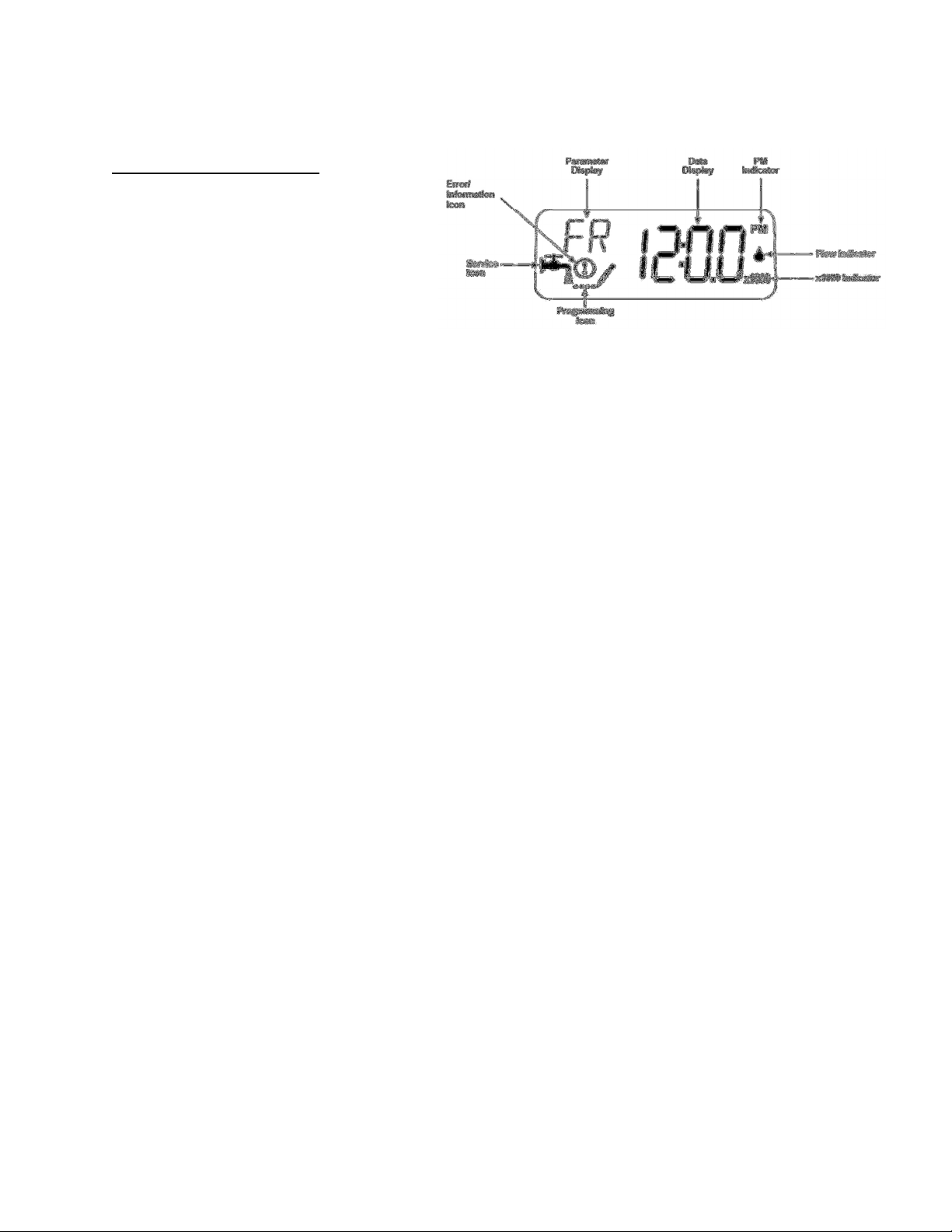
SETTING THE CONTROL
The Iron Genie uses the Fleck
model SXT po er head to manage
the regeneration process.
While in the “Service” position the
display ill alternate bet een time of day and days remaining till regeneration.
The clock uses a standard 12 hour display.
The regeneration cycle is preset to occur at 12:30A.M. every second day. This
timing and frequency of regeneration can be modified as required.
The duration of the regeneration cycle is approximately 50 minutes.
1. Back ash cycle, 10 minute duration. Water flo is reversed inside
the unit to lift and reclassify the filter media rinsing accumulated
iron from the bed.
2. Oxygen refill, 40 minute duration. The unit empties of ater and is
filled ith air. During this cycle ater ill run to drain. There is a
slight delay at the start of the cycle hile the pressure of the air
ithin the tank reaches atmospheric pressure. During this time no
air is dra n into the tank. Once the pressure has equalized, you
ill hear as air is dra n into the unit.
3. The unit returns to the In-Service position. When this happens
ater continues to enter the tank, compressing the air into a
bubble in the top portion of the tank. Air bubble volume ill vary
slightly ith the local conditions.
Untreated ater is available during regeneration cycle.
Should you require the unit to regenerate at a time of day other than 12:30 A.M.
it is important that no other unit, softener or filter, regenerates at the same
time. This ill interfere ith the regeneration process of the Iron Genie.

In condition of high ater usage and/or high levels of iron, the unit may need to
regenerate more frequently than the standard three day cycle. The unit can be
set for every other day regeneration or daily regeneration, as required. Do not
set the regeneration frequency of longer than every three days as this risk
fouling the filter medium and can, over time, render the unit inoperable.
SETTING THE TIME OF DAY
Press and hold the Up or Do n
buttons until the programming icon
replaces the service icon and the
parameter display reads TD.
Adjust the displayed time ith
the Up and Do n buttons.
When the desired time is set,
press the Extra Cycle button to resume
normal operation. The unit ill also
return to normal operation after 5
seconds if no buttons are pressed.
INITIATING A REGENERATION
Press the Extra Cycle
button. The service icon
ill flash to indicate that
regeneration is queued.
To cancel a queued
regeneration press
the Extra Cycle Button.
Regenerate Immed ately
Press and hold the Extra
Cycle button for five
seconds.

IRON GENIE MASTER PROGRAMMING GUIDE
Press the Up or Do n Arro Buttons to enter the Time of Day
Programming Mode, Set the Time of Day Display to 12:01 P.M.
Press the Extra Cycle Button once to exit the Time of Day Programming
Mode.
With the Time of Day Display set to 12:01 P.M., Push and hold the Up
and Do n Arro Buttons for 7 seconds.
Press the Extra Cycle Button once to advance to next parameter.
1.
DF - GAL - US Gallon Display Format
2.
VT - dF1b – Do n flo , Single Back ash
3.
CT - tc - Time Clock Control
4.
NT - 1 - Single Tank System
5.
DO - 3 - Day Override
6.
RT - 12:30 A.M. - Time of Regeneration
7.
BW - 10 - 10 Minute Back ash
8.
BD - 40 - 40 Minute Air Recharge (80 minutes for ECM model)
9.
RR - OFF - Rapid Rinse is Turned Off
10.
Exit Master Programming and Return Valve to Service Display
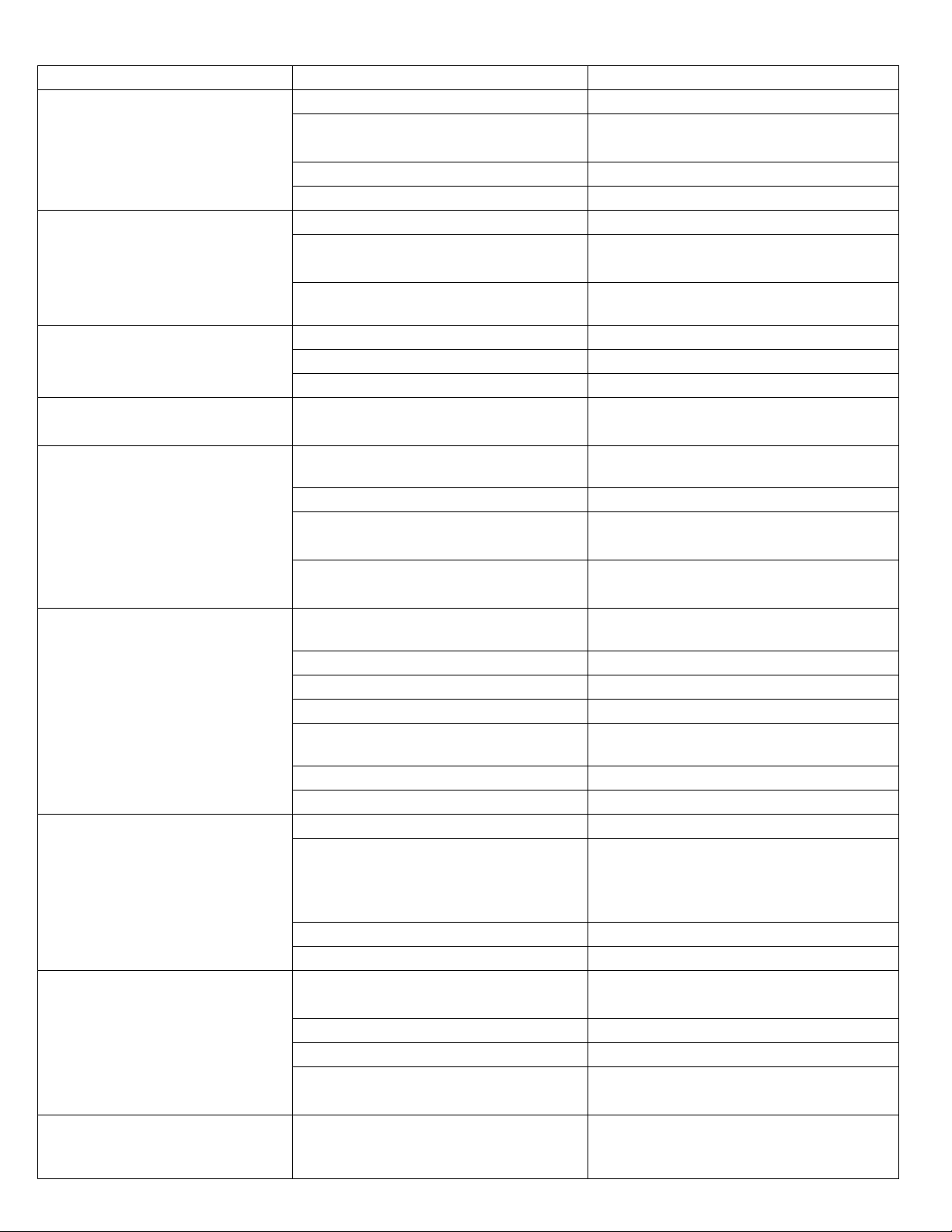
Troubleshoot ng
Problem Possible Cause Solution
No Display on PC Board
No po er at electric outlet Repair outlet or use orking outlet
Control valve Po er Adapter not
plugged into outlet
Plug Po er Adapter into outlet
Defective Po er adapter Replace Po er Adapter
Defective Circuit Board Replace Po er Head Assembly
Circuit Board does not display
correct time of day
Po er Outage Reset time of day
Po er Adapter plugged into electric
outlet controlled by light s itch
Use uninterrupted outlet
Tripped breaker s itch and/or tripped
GFI Reset breaker s itch and/ or GFI s itch
Control valve regenerates at
rong time of day
Po er Outage Reset to correct time of day
Time of day not set correctly Reset to correct time of day
Time of regeneration set incorrectly Reset regeneration time
Time of day flashes on and off
Po er Outage
Press
any button to stop the time of day
from flashing
Unit does not regenerate
Electrical Service to unit is interrupted
Use uninterrupted outlet. Reset time of
day
Po er failure Reset time of day
Not Programmed
Enter Master Programming mode and
verify that the unit is configured properly
Defective Timer
Verify that days advance on main di
s
play.
If not replace Po er Head Assembly
Unit does not dra air in "BD"
cycle
Injector is plugged
Clean or replace injector throat and
nozzle
Injector screen is plugged Clean or replace injector screen
Line to drain is crimped or plugged Replace drain line
Drain line flo control is plugged Clean drain line flo control
Line pressure is too lo
Increase line pressure to
minimum
of 20
psi
Internal control leak Replace seals and spacers
Main drive gear grooved Replace main drive gear
Water to drain continuously
Motor stopped or jammed Replace motor if necessary
Foreign material in control
Remove po er head assembly and
inspect bore. Remove foreign material
and check control in various regeneration
positions
Internal control leak Replace seals and spacers
Main drive gear grooved Replace main drive gear
Air in house line or at faucets
Iron Genie regenerating at same time
as other equipment is regenerating
Reset to correct time of day and verify
regeneration time of all equipment
Worn seals Replace seals and spacers
Distributor O-ring damaged Replace distributor O-ring
Inadequate ater supply to meet
back ash requirements
Verify ater supply and proper flo rate
Control cycles continuously
Misadjusted, broken, or shorted s itch
Determine if s itch or timer is faulty and
replace it, or replace complete po er
head assembly

Troubleshoot ng
Error
Code
Error
Type Cause Reset and Recovery
0
Cam
Sense
Error
The valve drive took
longer than 6 minutes
to advance to the
next regeneration
position.
Unplug the unit and examine the po er
head. Verify that all
cam s itches are connected to the circuit board and
functioning properly. Verify that the motor and drive train
components are in good condition and assembled properly.
Check the valve and verify that the piston travels freely.
Repla
ce /reassemble the various components as necessary.
Plug the unit in and observe its behavior. The
unit should cycle
to the next valve position and stop. If the error re-occurs,
unplug the unit and contact your ater treatment dealer.
1
Cycle
Step
Error
The control
experienced an
unexpected cycle
input
Unplug the unit and examine the po er
head. Verify that all
cam s itches are connected to the circuit board and
functioning properly. Enter Master Programming mode and
verify that the valve type and system type are set correctly
ith regard to the unit itself.
Step the unit through a
manual regeneration and verify that it
functions correctly. If the error re-occurs unplug the unit and
contact you ater treatment dealer.
2
Regen
Failure
The system has not
regenerated for more
than 99 days
Perform a manual regeneration to reset the
error code.
Enter the Master Programming Mode and verify that the unit
is configure properly.
3
Memory
Error
Control board
memory failure
Perform a Master Reset and reconfigure the system via Master
Programming mode. After reconfiguring the system, step the
valve through a manual regeneration. If the error re-occurs
unplug the unit and contact your local ater treatment dealer.
UD
Upper
Drive
Sync
Po er failure install
programming change
Valve ill automatically recover.
Resets
Soft Reset: Press and hold the Extra Cycle and Do n Buttons for 25 seconds hile in normal service mode.
This resets all parameters. Check and verify all parameters in master programming.
Master Reset: Hold the Extra Cycle button hile po ering up the unit. This resets all parameters. Check and
verify all parameters in mater programming

Power Head Assembly

Valve Power Head Asse bly, Continued
Item No. Quant ty Part No. Descr pt on
1
......................1 ..................26001-02 ..............Housing, Control Valve Drive
2
......................2 ..................12473 ....................Scre , Hex Wsh 10-24 x 5/8
3
......................1 ..................19474 ....................Harness, Po er, 56SXT, Elect
4
......................1 ..................13299 ....................Washer, Spring, 3/8
5
......................1 ..................13017 ....................Gear, Idler
6
......................1 ..................23045 ....................Gear, Drive, 6700
7
......................1 ..................13175 ....................Plate, Motor Mounting
8
......................4 ..................13296 ....................Scre , Hex Wsh, 6-20 x 1/2
9
......................1 ..................16944 ....................Motor, Drive, 24V 60 Hz 2 rpm
10
......................2 ..................11384 ....................Scre , Phil, 6-32 x 1/4 Zinc
11
......................1 ..................13168 ....................Cam, Brine Valve, 5600
12
......................1 ..................12037 ....................Washer, Plain, #10 18-8 SS
13
......................1 ..................40214 ....................Scre , Hex Wsh, #6-20 x 3/4
14
......................2 ..................19080 ....................Spring, Compression, 6700
15
......................2 ..................13300 ....................Ball, 1/4” Stainless Steel
16
......................1 ..................42933 ...................Gear, Main Drive, SXT
17
......................1 ..................13547 ....................Strain Relief, Flat Cord
18
......................1 ..................19674 ....................Transformer, 24V, 9.6VA
19
......................1 ..................40338 ....................Cover, Back Drive Housing
20
......................1 ..................19079 ....................Washer, Friction
21
......................1 ..................17438 ....................Cam, 56SXT/6700, Do nflo
22
......................1 ..................15151 ....................Scre , Flat Hd St, 6-20 x 3/4
23
......................2 ..................10218 ....................S itch, Micro
24
......................1 ..................10302 ....................Insulator, Limit S itch
25
......................2 ..................17876 ....................Scre , Phil, Pan, 4-40 x 1 1/8
26A ......................1 ..................61672-0201 ..........Front Panel Assy, 56SXT, Square, Black
26B ......................1 ..................61673-0201 ..........Front Panel Assy, 56SXT, Curved, Black
27.........................2 ..................13898 ....................Scre , Flat Hd, Phil Steel
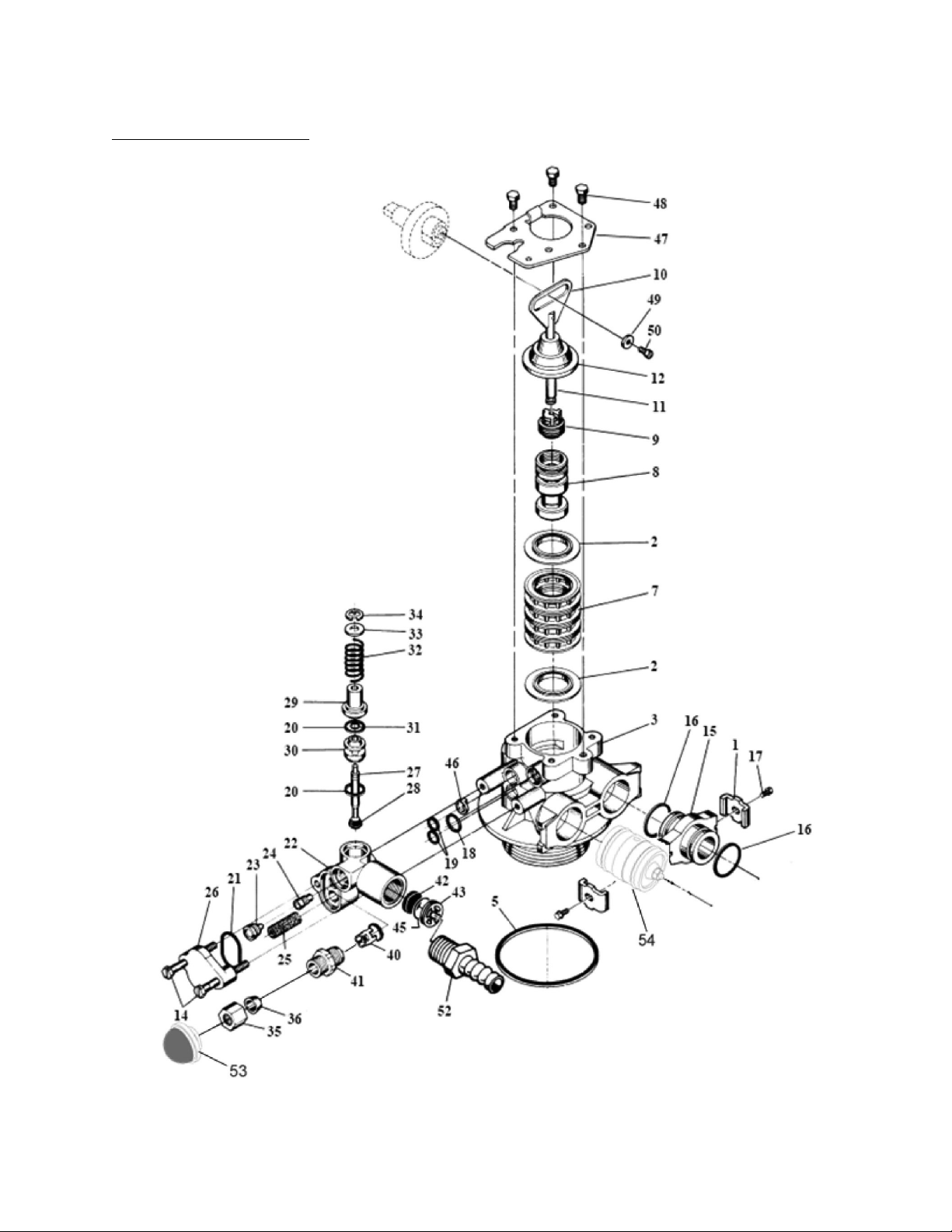
CONTROL VALVE ASSEMBLY

Control Val e Assembly, Continued
Item No. Quant ty Part No. Descr pt on
1............................2............................13255..........................Adapter Clip
2............................5............................18759..........................Seal, Lo Drive Force
3............................1............................61400-12....................Valve Body Assembly, 1 Dist.
4............................1............................13304..........................O-ring, Distributor Tube, 1
5............................1............................12281..........................O-ring, Top of Tank
7............................4............................14241..........................Spacer
8............................1............................17218-IG....................Piston, Proprietary
9............................1............................10696..........................Piston Pin
10..........................1............................13001-04....................Rod, Piston, 56SXT/6700
11..........................1............................14309..........................Retainer, Piston Rod
12..........................1............................13446-41....................Plug, End, 56SXT/6700, Green
14..........................2............................13315..........................Scre , Injector Mounting
15..........................1............................19228-01....................Adapter Assy,Coupling,5600, /O-ring
16..........................4............................13305..........................O-ring, Adapter Coupling
17..........................2............................13314..........................Scre , Adptr Coupling
18..........................1............................12638..........................O-ring, Drain
19..........................2............................13301..........................O-ring, Injector
20..........................2............................13302..........................O-ring, Brine Spacer
21..........................1............................13303..........................O-ring, Injector Cover
22..........................1............................13163..........................Injector Body
23..........................1............................10913-x......................Injector Nozzle, specify size
24..........................1............................10914-x......................Injector Throat, specify size
25..........................1............................10227..........................Injector Screen
26..........................1............................13166..........................Injector Cover
27..........................1............................13172..........................Brine Valve Stem
28..........................1............................12626..........................Brine Valve Seat
29..........................1............................13165..........................Brine Valve Cap
30..........................1............................13167..........................Brine Valve Spacer
31..........................1............................12550..........................Quad Ring
32..........................1............................11973..........................Spring, Brine Valve
33..........................1............................16098..........................Washer, Brine Valve
34..........................1............................11981-01 ....................Retaining Ring
35..........................1............................10329...........................BLFC Fitting Nut
36..........................1............................10330..........................BLFC Ferrule
40..........................1............................41861..........................Neo Check
41..........................1............................13244..........................BLFC Fitting, 3/8
42..........................1............................12408..........................DLFC Button, specify size
43..........................1............................13173-01....................Retainer, DLFC, Button, /O-ring
46..........................1............................13497..........................Air Disperser
47..........................1............................13546..........................End Plug Retainer
48..........................3............................12112..........................Scre
49..........................1............................13363..........................Washer
50..........................1............................13296..........................Scre
52..........................1............................13308..........................Drain Hose Barb
53..........................1............................19856..........................Inlet Screen
54..........................1............................300-038WW ..............Plastic Inlet Check Valve
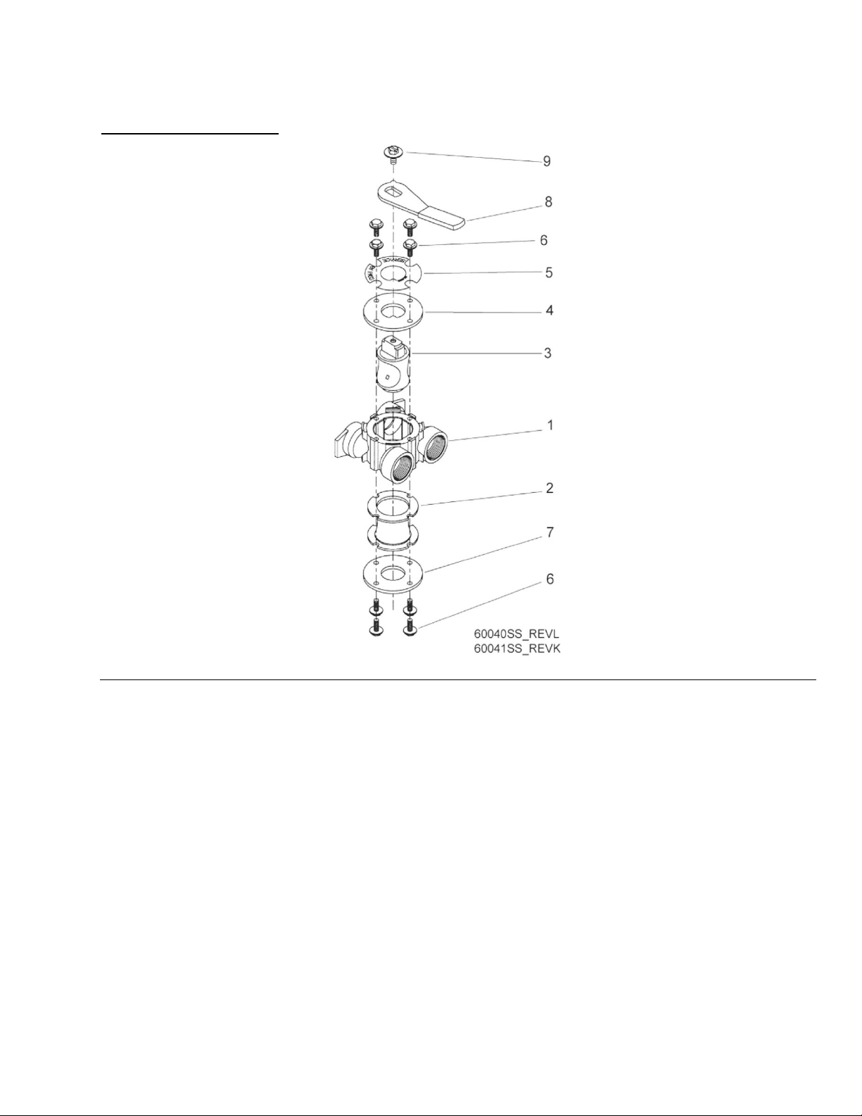
BYPASS VALVE ASSEMBLY
Item No. Quant ty Part No. Descr pt on
1
......................1 ......................17290 ....................Bypass Valve Body, 3/4”
........................1 ......................13399 ....................Bypass Valve Body, 1”
2
......................1 ......................14105 ....................Seal, Bypass
3
......................1 ......................11972 ....................Plug, Bypass
4
......................1 ......................11978 ....................Side Cover
5
......................1 ......................13604-01 ..............Label
6
......................8 ......................15727 ....................Scre
7
......................1 ......................11986 ....................Side Cover
8
......................1 ......................11979 ....................Lever, Bypass
9
......................1 ......................11989 ....................Scre , Hex Head, ¼-14

RECOMMENDED IRON FILTER SERVICE KIT
13001-04 Piston Rod Assembly
13446-41 End Plug Assembly, Green
60125-02 Seal and Spacer Kit, Lo Drive Force
10913-2 Injector Nozzle #2, Blue
10914-2 Injector Throat #2, Blue
10227 Screen
42933 Main Drive Gear
60032 Brine Valve
13302 O-ring, Brine Valve
IOK Injector Body O-Ring Kit

Service Instructions
Power Head Replacement
1. Unplug Po er Head from electrical outlet.
2. Remove the Po er Head back cover.
3. Remove black scre and silver asher at drive yoke on piston rod.
4. Remove 2 silver timer mounting scre s.
5. Lift off entire Po er Head assembly.
6. Put ne Po er Head on top of control valve. Be sure drive pin on main gear engages slot in drive
yoke.
7. Replace black scre and silver asher at drive yoke on piston rod.
8. Replace the 2 silver Po er Head mounting scre s.
9. Plug electrical cord into outlet.
10. Set time of day and cycle the control valve through an immediate regeneration to assure proper
function.
11. Replace the Po er Head back cover.
Injector/Screen Replacement
1. Move the integral stainless steel bypass to the bypass position.
2. Relieve the ater pressure in the Iron Genie by holding do n the Extra Cycle button for 5 seconds.
Once in the “BW” cycle pressure ill be relieved.
3. Push extra cycle button to move control valve to “BD” cycle.
4. Push extra cycle to return the control valve to the service position (time of day on display).
5. Unplug Po er Head from electrical outlet.
6. Remove the t o injector body mounting scre s.
7. Remove injector cap.
8. Remove injector screen.
9. Unscre and remove injector nozzle and throat.
10. Scre in ne injector throat and nozzle.
11. Install ne screen.
12. Insert scre s through injector cap and injector body in to mating holes in the valve body. Tighten
scre s.
13. Return bypass to service position. Water pressure automatically builds in tank.
14. Check for leaks.
15. Plug electrical cord into outlet.
16. Set time of day and cycle the control valve through an immediate regeneration to assure proper
function.

Br ne Valve Replacement
1. Move the integral stainless steel bypass to the bypass position.
2. Relieve the ater pressure in the Iron Genie by holding do n the Extra Cycle button for 5 seconds.
Once in the “BW” cycle pressure ill be relieved.
3. Push extra cycle button to move control valve to “BD” cycle.
4. Push extra cycle to return the control valve to the service position (time of day on display).
5. Unplug Po er Head from electrical outlet.
6. Remove the control valve back cover.
7. Remove black scre and silver asher at drive yoke.
8. Remove 2 silver timer mounting scre s.
9. Lift off entire Po er Head assembly.
10. Remove the t o injector body mounting scre s.
11. Slide the injector body a ay from control valve.
12. Pull brine valve from injector body.
13. Discard o-ring at bottom of brine valve hole in injector body.
14. Install ne o-ring at bottom of brine valve hole in injector body.
15. Press brine valve into brine valve hole in injector body. Be sure shoulder bushing on brine valve is
flush ith injector body.
16. Slide injector body onto control valve.
17. Insert scre s through injector cap and injector body in to mating holes in the valve body. Tighten
scre s.
18. Put Po er Head on top of control valve. Be sure drive pin on main gear engages slot in drive yoke.
19. Replace black scre and silver asher at drive yoke.
20. Replace the 2 silver timer mounting scre s.
21. Return bypass to service position. Water pressure automatically builds in tank.
22. Check for leaks.
23. Plug electrical cord into outlet.
24. Set time of day and cycle the control valve through an immediate regeneration to assure proper
function.
25. Replace the Po er Head back cover.

P ston Rod and End Plug/Seal and Spacer Replacement
1. Move the integral stainless steel bypass to the bypass position.
2. Relieve the ater pressure in the Iron Genie by holding do n the Extra Cycle button for 5
seconds. Once in the “BW” cycle pressure ill be relieved.
3. Push extra cycle button to move control valve to “BD” cycle.
4. Push extra cycle to return the control valve to the service position (time of day on display).
5. Unplug Po er Head from electrical outlet.
6. Remove the control valve back cover.
7. Remove black scre and silver asher at drive yoke on piston rod.
8. Remove t o silver timer mounting scre s.
9. Lift off entire Po er Head assembly.
10. Remove three silver scre s on stainless steel end plug retainer plate.
11. Remove end plug retainer plate.
12. Pull up on end of piston rod yoke until piston is out of valve.
13. Remove five rubber seals and four plastic spacers from valve body.
14. Replace the five rubber seals and four plastic spacers.
15. Take the piston assembly ith the ne piston rod and cap and push piston into valve by means
of the end plug. DO NOT pull up on piston rod.
16. Replace end plug retainer plate
17. Replace three silver scre s on end plug retainer plate.
18. T ist yoke in a clock ise direction to align it ith main drive gear.
19. Put Po er Head on top of control valve. Be sure drive pin on main gear engages slot in drive
yoke.
20. Replace black scre and silver asher at drive yoke.
21. Replace the 2 silver timer mounting scre s.
22. Return bypass to service position. Water pressure automatically builds in tank.
23. Check for leaks.
24. Plug electrical cord into outlet.
25. Set time of day and cycle the control valve through an immediate regeneration to assure proper
function.
26. Replace the Po er Head back cover.
This manual suits for next models
2
Table of contents
Other Addie Water Systems Water System manuals


