Addvent AVACSPL12N Mounting instructions

AVACSPL12N and AVACSPL18N
Split Air Conditioners
Installation Instructions and User Guide
IMPORTANT SAFEGUARDS
WHEN USING ANY ELECTRICAL APPLIANCE, BASIC SAFETY PRECAUTIONS
SHOULD ALWAYS BE FOLLOWED.
PLEASE READ ALL INSTRUCTIONS CAREFULLY
AND RETAIN FOR FUTURE REFERENCE
AVACSPL12+18Ninstructions 12/3/08 09:06 Page 1

CONTENTS
Features and part list 2
Safety Awareness 3
Installation 4
Technical features 8
Operation
The Remote Control and the display screen 9
Preparing to use the appliance 11
Automatic Operation 12
Select Operation Mode (cooling, dehumidifying and heating) 12
Air Speed and Air Flow Adjustment 13
Sleep Mode 14
Sweep Operation 13
Timer Operation (ON/OFF Timer) 14
Tips for Operation 15
Maintenance and cleaning 15
Specification 16
2
Figure 2
FEATURES
Figure 1
Figure 3
Figure 3a
• Outdoor unit
• Indoor unit
• Remote control
PARTS LIST
FRONT PANEL
AIR RETURN OPENING
POWER PLUG
LCD DISPLAY
AIR DIRECTIONAL BLADES
AIR INLET EMERGENCY
SWITCH
WATER DRAIN
PIPING
WATER DRAIN HOSE
VENTILATION GRILLE
AVACSPL12+18Ninstructions 12/3/08 09:06 Page 2

SAFETY
IMPORTANT SAFEGUARDS
WHEN USING ANY ELECTRICAL APPLIANCE, BASIC SAFETY PRECAUTIONS
SHOULD ALWAYS BE FOLLOWED.
PLEASE READ ALL INSTRUCTIONS CAREFULLY
AND RETAIN FOR FUTURE REFERENCE
This manual should be read before the appliance is installed.
Please read the DOs and DON’Ts listed below before undertaking the installation of this appliance
DOs
Isolate the power before cleaning this appliance.
Unplug the appliance if it is not to be used for long periods.
Check the condition of the outdoor mounting brackets form time to time to ensure that they are in a good condition.
Ensure that the appliance is not operated when doors and windows are open.
In areas of high humidity a suitable circuit breaker needs to be installed, please contact a suitable electrical contractor
for this.
Ensure that the condensation drain is unobstructed.
DON’Ts
DO NOT install this appliance on your own. This appliance needs to be installed by two people.
DO NOT use this appliance if the power cable is damaged.
DO NOT unplug the appliance when in operation.
DO NOT insert fingers into this appliance.
DO NOT extend the power cable.
DO NOT run the appliance off an extension cable.
DO NOT install this appliance on your own.
DO NOT pull on the power cable.
DO NOT clean this appliance with a wet cloth.
This appliance is not meant for installation in a kitchen or bathroom.
DO NOT climb on indoor or outdoor unit.
This appliance is meant for domestic use only.
DO NOT operate this appliance during a thunder storm.
DO NOT install this appliance where there is a risk of escaping inflammable gas.
3
AVACSPL12+18Ninstructions 12/3/08 09:06 Page 3
For correct installation, read this manual before starting
installation.
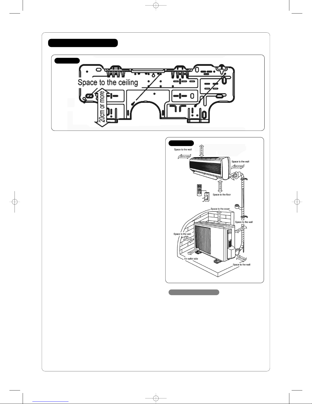
Choosing the installation position
Locate the indoor unit in:
a place where there is no obstacle near the inlet and outlet
area.
a place which can bear the weight of the indoor unit.
a place that provides space around the indoor unit as
shown in Figure 5.
a place away from heat, steam and inflammable gas.
Locate the outdoor unit:
in a place which is convenient and not exposed to strong
winds.
in a place that can bear the weight of the outdoor unit and
where the outdoor unit can be held in the horizontal
position.
in a place where the operational noise and discharged air
does not disturb others.
in a place free of a leakage of combustible gas.
with an allowable head level at the connection piping is less
than 5m and length of the connection piping is no more
than 10m.
in a place that provides space around the outdoor unit as
shown in Figure 5.
on a rigid base or structure to prevent excessive noise and
vibrations.
firmly anchored the in position.
4
INSTALLATION
Figure 4
Figure 5
Installation accessories
Mounting Plate
M4x30 Torque Screws
Plastic Binder
Plastic Draining Hose
PVC Bond Tape
Remote Controller
AVACSPL12+18Ninstructions 12/3/08 09:06 Page 4
Installing the indoor unit
Positioning the mounting plate
Install directly on the wall
Select a structural part of the wall, so that indoor unit can be installed
securely.
Make sure the mounting plate is level before securing it.
The wall must be capable of carrying the weight of the indoor unit.
Note: The indoor unit must be installed more than 2.3m above the floor for the best
efficiency.
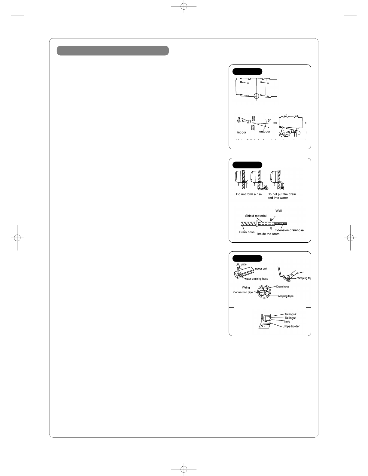
Install the piping hole
Drill hole with 65mm core drill.
Insert the through wall pipe into the hole
Note: Drill the hole from indoors to outdoors with a 5° downward inclination.
Indoor unit installation preparation
Install the drain hose
Run the drain hose sloping downward.
Do not install the drain hose as illustrated (see figure 7).
When connecting extension drain hose insulate the connecting part of
extension drain hose with a shield material.
Indoor unit electrical wiring
The indoor unit electrical wiring is already connected to the indoor unit
during manufacture.
If the wiring or any other part is damaged, please contact Addvent on
0117 923 5375.
Wrap the pipe and wiring.
Hold down the end of the pipe, pull it out, form the extension part.
Wrap the piping and wiring and pull them through the cut-off-tailings hole.
When routing the pipe and wire from the left or right side of the indoor
unit, cut off the tails from the pipe holder if necessary.
NOTE: EMC Directive 89/336/EEC to prevent flicker impressions during the start of
the compressor (technical process) and the adverse influence caused by the
second harmonics of the compressor, the following installation conditions apply.
The power connection for the air conditioner has to be done at the main power
distribution. The distribution has to be of a low impedance, normally the required
impedance reaches at a 32A fusing point.
2 No other equipment has to be connected with this power line.
3 For detailed installation acceptance, please refer to your contractor with the power
supplier if restrictions do apply for products like washing machines, air conditioner
or electrical ovens.
4 For power details of the air conditioner, refer to the rating plate of the product.
5 For any further questions contact Addvent on 0117 923 5375.
5
Figure 6
Figure 7
Figure 8
AVACSPL12+18Ninstructions 12/3/08 09:06 Page 5
9
8
6 7
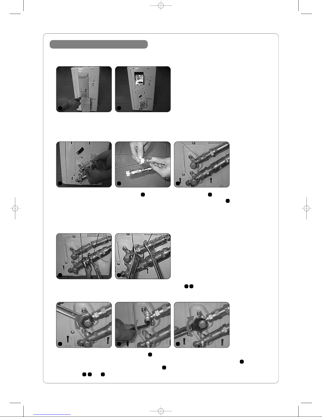
Installing the outdoor unit
6
Install the connection pipe to the outdoor unit
Install the connection pipe with quick-coupling
Remove the protection cover before connecting the coupling pipe and electric wiring.
Tighten the shut-off valve nut firmly with torque wrench as shown in .
Fasten the larger coupling first and then the smaller coupling.
Quick coupling installation procedure
1
3
6 7
4 5
2
8 9 10
10
3 4
5
Take off the plastic nuts at the outdoor unit and connection pipe quick couplings .
Align the centre of the outdoor unit quick coupling and screw the quick coupling pipe by hand .
Do not use torque wrench to turn the nuts as it may cause leakage.
Do not shake the coupling during tightening it .
8 9 10
Undo the shut-off valve nut with torque wrench .
Open the shut-off valve with hex wrench, turn counter clockwise till open and reverse 180° clockwise .
Tighten the shut-off valve nut firmly with torque wrench .
Repeat steps and for the larger coupling.
AVACSPL12+18Ninstructions 12/3/08 09:06 Page 6
7
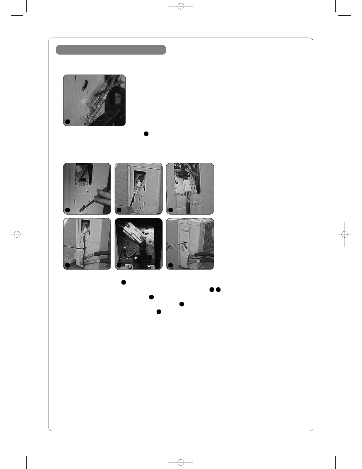
Installing the outdoor unit
Quick coupling installation procedure continued
Connect the electric wiring at the outdoor unit
11
12 13 14
15 16 17
11
Check for leakage using soapy water .
12
13 14
15
16
17
Before connecting the electric wiring at the outdoor unit, make sure the power of indoor unit is unplugged.
Remove the cable clamp .
Connect the electric wiring to outdoor unit with the wiring connector .
Tighten the cable with the cable clamp .
Please connect the Earthing to the housing as shown in .
Replace the shut-off valve protective cover .
AVACSPL12+18Ninstructions 12/3/08 09:06 Page 7

Technical Features
Automatic Function: This unit is equipped with fuzzy logic control.
This Technology allows the appliance to sense the conditions within the room to give you the most comfortable
atmosphere at any given time. It works through optimal program design, which makes control clearer avoiding
unnecessary over cooling or overheating, resulting in greater energy savings.
Lower Noise: The large diameter fan blade design reduces operational speed, furthermore reducing noise with same air
output. The lowest noise at comfortable sleeping operation mode is only 29dB.
Simple Operation: The hand held remote control displays clear and easy to understand symbols, making operation
simple and convenient.
Sleep Function: Intelligent fuzzy logic control ensures a comfortable sleeping environment,
24-hour Programme Timer: Setting on time, off time and on/off time within a 24 hour period.
Auto Air Speed Adjustment: Auto setting high, medium and low air speeds as per difference between set
temperature and room temperature
Sweep Function: Prevents localised over cooling, saves energy.
Auto Cool/Warm operation: Horizontal air flow when cooling and downward air flow when heating.
Adjustable air flow and direction.
Thermal Start System: Will not expel cold air when at the start of heating or defrosting cycles.
Independent Dehumidifying; Automatically , dehumidifies the area without changing room temperature
Self-Diagnostic function: on the indoor unit the TIMER and RUN indicating lights flash when there is a fault,
indicating fault type and the location.
Fan Motor: Maintains constant speed
Rotary Compressor: Reduced noise and vibration.
Cost effective and energy efficient design.
Microprocessor Control: Microprocessor with advanced technology can simply realise on-time operation, keeping
room temperature stable.
8
AVACSPL12+18Ninstructions 12/3/08 09:06 Page 8

9
Figure 9
The Remote Control
Operation see figure 9
To turn ON/OFF LED display simply by pressing the button.
NOTE:
Indoor LED display can be turned ON/OFF whether the unit is running or not. When the LED is turned ON and the
unit is OFF, the LED display will show indoor temperature; when the LED is turned ON and the unit is running,the
LED display will show running status.
When LED display is OFF, a symbol is shown on the remote controller.
When the LED display is turned OFF, you can still control all functions.
The timer function will not be affected ,even when the LED display is turned OFF.
When the power cord is unplugged or power failure suddenly, the AUTO RESTART function of PCB will let the LED
display ON again even if you choose the LED display ON or OFF when the power is resumed.
AVACSPL12+18Ninstructions 12/3/08 09:06 Page 9

10
Figure 10a
Cooling
Figure 10b
Heating
The Display
Instruction of Display see figure 10a and 10b
Power is supplied (standby): Number LED indicates room temperature.
Operating: Operating LED, Operation mode LED and indoor fan speed LED flash, Number LED indicates room
temperature. Fan speed LED flash showing Fan speed when indoor Fan is operating. Fan speed LED turns off when
indoor fan stops.
Temperature setting: Number LED indicating setting temperature (Number LED display"--" when setting nonstop
operation) and flashing. After 5 sec. Of temperature setting, Number LED stop flashing and then indicates room
temperature.
Fan speed setting: When high speed is selected, the Fan speed LED flashes quickly.
Time setting: When the timer mode is set the timer operation LED flashes; when the timer operation finishes the
timer operation LED turns off.
Sleep setting: When the sleep mode is set, the sleep operation LED flashes, when exiting sleep mode the sleep
operation LED turns off.
Cooling/Heating/Auto/Dehumidifying/Fan mode: After operating sleep mode for five minutes only the sleep
LED and mode LED lights remain illuminated, while all other LED lights turn off, keeping all remaining operating
functions unchanged.
AVACSPL12+18Ninstructions 12/3/08 09:06 Page 10

Preparing to use the appliance
11
Prior to operation
Figure 12
Figure 13
Indoor unit
Before starting to programme the remote control:
Plug into the mains, press the power switch on the indoor unit.
Remote control
Setting real-time
Open back cover, put in batteries
Press reset button see figure 12.
Press clock set button see figure 13.
Press (time setting button) and set correct time
Press clock set button again, replace the back cover see figure 13.
Control Operation Remote
The signal can reach within six meters directly in front of indoor unit.
when the button is pressed, indoor unit will beep once or twice, indicating
the receiving of the signal.
If no beep is heard, press again.
Always handle remote control carefully.
When mounting on the wall
Select a place where indoor unit can receive remote control signal, and fix
the holder.
Remote Control cannot be used
(emergency operation)
In case the batteries in the remote controller have gone flat, or the remote
controller is faulty, use emergency switch see figure 3a.
Press emergency operation switch.
Every time the button is pressed, it changes in sequence of emergency
Auto stop.
In the first 30 minutes, the temperature adjustment will not work, it will
maintain continuous operation and air flow see figure 14.
Press this button when the unit is on, the unit turn off.
Press this button when the unit is set on or off-timer mode, then the unit
stop the present mode and will be in stand by state.
Figure 14
OPERATION Cooling Heating
SET TEMPERATURE 24°C 24°C
AIR SPEED Medium Medium
AIR DIRECTING BLADES Auto Auto
Figure 11
AVACSPL12+18Ninstructions 12/3/08 09:06 Page 11

Operation
12
Figure 15
Figure 17
Figure 16
ROOM TEMP OPERATION TARGET TEMP
AT START UP MODE PRIMARY CONDITION
Above 25°C Cooling About 24°C
21–25°C Dehumidifying –
Below 21°C Heating About 24°C
Auto Operation see figure 15
To select the Auto Operation Function press the MODE button.
A slight touch can initiate Auto Operation, effectively turns the room
ambient to its most comfortable condition.
Start operation
Press I/O button,
When AUTO operation is displayed, the air conditioner will set the room
temperature to the most comfortable condition.
Stop operation
Press I/O button
To decrease temperature, press button TOO HOT
Every time you press this button, it reduces the temperature 1°C.
To increase temperature, press button TOO COLD
Every time you press this button, it raises the temperature 1°C.
When auto operation is not displayed, press MODE or to set it to
auto operation mode.
Every time the button is pressed. operation mode changes in sequence of
AUTO COOL DRY HEAT or FAN (for Indoor display cooling only
unit).
Operating modes
When started, operation mode will turn into cooling or dehumidifying or
heating as per room temperature. lf operation stops for two hours, it restarts
in the same set mode as before operation was stopped even if room
temperature has changed. lf you do not like the start-up mode, press MODE
to reselect an alternative mode.
NOTE: When the desired temperature in the room is above or below the set
temperature by 2°C, set either COOL or HEAT function to change the
temperature to the desired level. This change may take a short time to take
effect.
Select Operation Mode (cooling,
dehumidifying, heating) see figure 17
Select operation to finely adjust temperature or air direction.
To select cooling, dehumidifying and heating.
Press I/O button
Press MODE to select operation mode.
Every time the button is pressed. operation mode changes in sequence of
AUTO COOL DRY HEAT .
For cooling only unit, operation mode changes in sequence of
AUTO COOL DRY HEAT .
Press I/O button
To change temperature
Press TOO HOT button to reduce temperature.
Every time you press it reduces 1°C.
Press TOO COLD button to increase temperature
Every time you press it increases 1°C.
AVACSPL12+18Ninstructions 12/3/08 09:06 Page 12
Operation
13
Figure 18
Figure 19
Figure 20
Figure 21
Note: Heating operation
The system may get overloaded if the air conditioner absorbs too much heat from
air. The fan of the outdoor unit stops automatically to protect air conditioner as
controlled by the microprocessor.
Dehumidifying operation
When the fan of the outdoor unit stops, it may show frost. This is normal.
When the temperature is in auto set, it can not be changed.
Operates at a temperature lower than room temperature.
If the ambient temperature is too high, cooling operation is under excessive load
condition, so the room temperature may not reach set temperature,(cooling
operation).
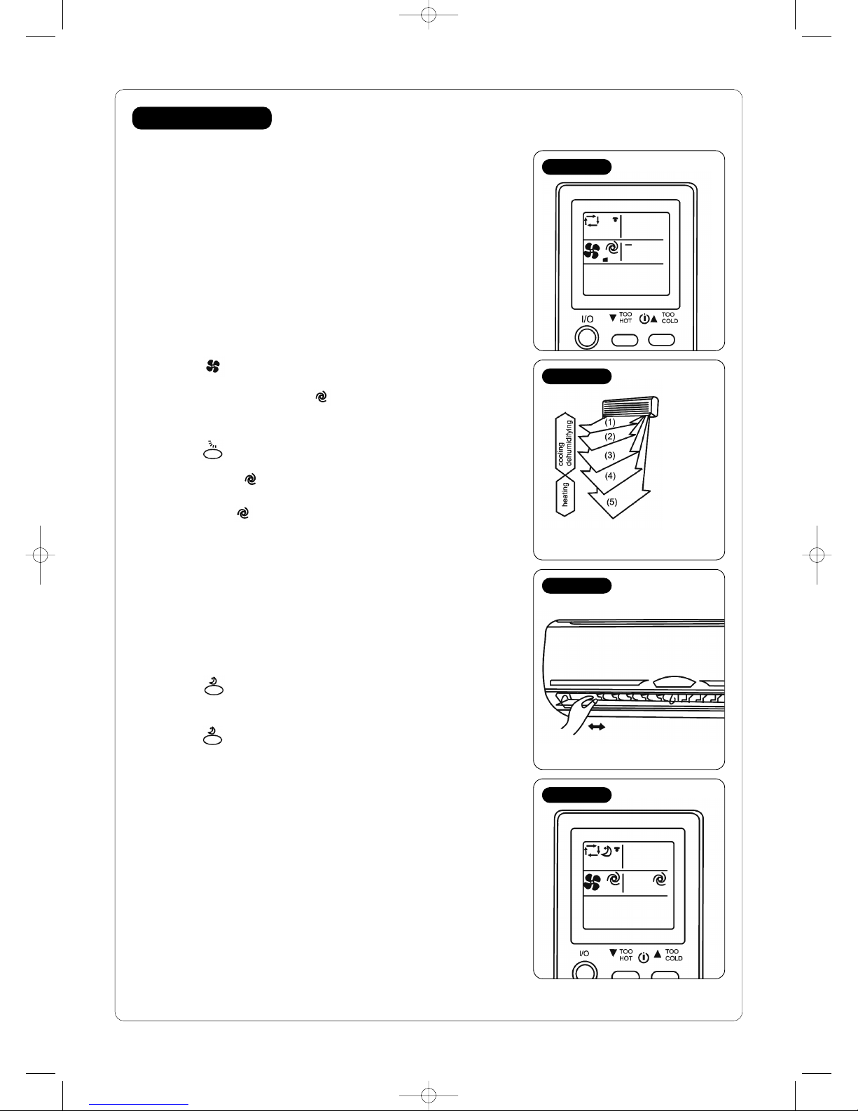
Air Speed and Air Flow Adjustment see figure 18
Press button to change air speed.
Every time the button is pressed, air speed changes in sequence of – low,
– medium, – high, – auto.
Select – high mode to cool entire room.
Select sleep operation to reduce the noise levels when you want to sleep.
Press to change up/down air direction.
Every time the button is pressed, air direction changes in sequence of (1)
(2) (3) (4) (5) –auto.
Recommended range of up/down air flow see figure 19
Adjust with –auto generally, select (1) (2) if in cooling of dehumidifying,
select (3) or (5) if in heating.
Air flow adjustment see figure 20
To change left/right air direction
Manually adjust the left/right air directing blades.
Complete adjustment before operation. DO NOT adjust during operation.
Comfortable Sleeping Operation see figure 21
To select this operation
Press
Start this operation when you want to have low noise levels.
To release this operation
Press again
Reduce the air flow from the indoor unit.
Note: Start this mode when you want to go to sleep. If you start this mode during
daytime, the ambient temperature may be too high and it will reduce the cooling
capacity.
AVACSPL12+18Ninstructions 12/3/08 09:06 Page 13

Operation
Sweep Operation see figure 22
By starting the sweep operation, every part of your room will receive cooled
air.
To select this operation.
Press
To release this operation
Press again.
Timer operation see figure 23
Timer ‘ON’ setting operation
Press during operation to set timer to desired time.
Every time this button is pressed, it changes in sequence of timer ‘ON’
release.
Press to set timer to correct time.
Every time you press the button, the hour changes by 1 and the minute
changes by 10.
To release this operation
Press to release timer
Timer ‘OFF’ setting operation
Press during operation to set of timer ‘OFF’
Every time this button is pressed, it changes in sequence of timer ‘OFF’
release.
Press button to set timer tocorrect time
Every time you press, hour changes by 1, minute changes by 10
To release this operation
Press to release timer
Program timer operation
Timer ‘ON’ and timer ‘OFF’ operations can be combined. The operation
nearest to the time set on the controller takes priority.
If the clock on the remote controller is not set to the correct time, the
timer operation will not be accurate.
14
Figure 22
Figure 23
AVACSPL12+18Ninstructions 12/3/08 09:06 Page 14
Maintenance
Cleaning
If the Air Conditioner is not to be used for a long time
Start fan only for 3-4 hours to completely dry the inside of the system.
Set free -selecting mode and select the highest set temperature when fan is turning.
Turn off air conditioner, unplug the mains.
Take the batteries out of the remote control.
When you want to use the air conditioner
Clean air filters and replace them to original position.
Inlets and outlets of indoor and outdoor units should not be covered/blocked.
The earth wire should not be loose.
Before cleaning
Unplug from the mains power supply.
Cleaning the indoor unit
Clean indoor unit with soft cloth
Do not use solvents or abrasive cleaning products to clean the indoor unit as they may cause damage.
Note: Turn off the system, unplug mains and turn off breaker before cleaning, high speed turning fan during operation may
cause injury.
15
Tips for operation
Cooling
How to make cooling more efficient
Close windows and reduce sunlight to increase the cooling effect.
Position the outdoor unit where it will be shielded from direct sunlight. This will reduce running costs.
Heating
A comfortable heat level lies in the difference with outside temperature.
The set temperature for heating will not be too different than outside temperature. Though this varies with area, set
the temperature to between 20–24°C. The heating effect decreases when the ambient temperature is below 5°C.
Dehumidifying
Humidity has a relation to temperature and wind. Generally speaking, the most comfortable humidity is 60%–75% in
summer and 55%–70% in winter. Temperature and speed are automatically selected by microprocessor.
AVACSPL12+18Ninstructions 12/3/08 09:06 Page 15
Telephone: 0117 923 5375 Fax: 0117 923 5374
Victoria Road, Avonmouth, Bristol BS11 9DB www.addvent.co.uk
ISSUE 1/0108
Waste electrical products should not be disposed of with household waste. Please recycle where facilities exist.
Check with your local authority or retailer for recycling advice
RoHS
COMPLIANT
Specifications
AVACSPL12N AVACSPL18N
Power supply 220-240V/50Hz 220-240V/50Hz
Cooling capacity kW 12,000 18,000
Rated input kW 3.5 5.1
Heating Capacity btu/h 13,500 19,000
kW 4.0 5.6
EER kW 3.21 2.83
Energy Class A C
COP kW 3.67 3.22
Energy Class A C
Refrigerant charge (5m) kG 1.00 1.45
Water proof class outdoor unit IP24
Dehumidification L/h 1.3 2.0
Power Input Cooling W 1,090 1,800
Heating W 1,090 1,740
Airflow H m3/h 520 800
M 450 700
L 380 600
Noise Level @ 1m H dB(A) 40 43
M3639
L3235
Dimensions indoor unit HxWxD mm 275x790x200 275x930x200
outdoor unit HxWxD mm 545x830x255 545x830x255
Net weight indoor unit kG 10 12
outdoor unit kG 34 40
IP
24
AVACSPL12+18Ninstructions 12/3/08 09:06 Page 1
This manual suits for next models
1
Table of contents
Other Addvent Air Conditioner manuals


