Addvent AVAC9000 Wiring diagram

IMPORTANT SAFEGUARDS
WHEN USING ANY ELECTRICAL APPLIANCE, BASIC SAFETY
PRECAUTIONS SHOULD ALWAYS BE FOLLOWED.
PLEASE READ ALL INSTRUCTIONS CAREFULLY
AND RETAIN FOR FUTURE REFERENCE
AVAC9000
Portable Air Conditioner
Installation Instructions
User Guide
2
BEFORE USE
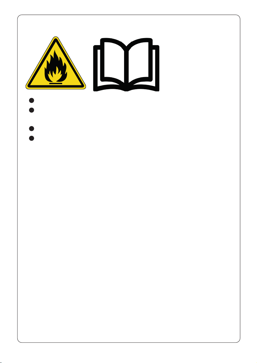
These symbols on your device mean:
This appliance is lled with Propane gas R290. Follow strictly the
manufacturer’s instruction concerning use and repairs!
Before using the machine, read carefully the entire instruction manual.
Do not install, operate or store the device in a room smaller than 11m
2
.
3
Safety Instructions
This appliance can be used by children aged from 8 years and above and
persons with reduced physical, sensory or mental capabilities or lack of
experience and knowledge if they have been given supervision or instruction
concerning use of the appliance in a safe way and understand the hazards
involved.
Cleaning and user maintenance shall not be made by children without
supervision.
Children of less than 3 years old should be kept away unless continuously
supervised.
Children aged from 3 years and less than 8 years shall only switch on/off
the appliance provided that it has been placed or installed in its intended
normal operating position and they have been given supervision or
instruction concerning use of the appliance in a safe way and understand
the hazards involved. Children aged from 3 years and less than 8 years shall
not plug in, regulate and clean the appliance or perform user maintenance.
Never use this appliance for anything other than its intended purpose.
Your air conditioner is designed to be used in a house, ofce and similar
conditions and should not be used for any other purpose.
If the supply cord is damaged, it must be replaced by a suitably qualied
person in order to avoid a hazard.
Always keep the unit in an upright position to avoid damage to the cooling
system.
Be sure that the air inlets and outlets are not blocked or covered.
Don’t put any object into the air inlet or outlet of the unit.
In order to avoid overheating, do not cover the unit while it is plugged in or
in-use.
Never connect the unit to a defective socket.
Never locate the appliance immediately below a socket-outlet.
Never unplug the air conditioner while it is operating. This could damage
the electronic circuits.
Leave at least 300mm space around the unit.
To avoid tripping the circuit, do not use an extension cord for this unit.
WARNING
4
To turn on your unit, insert the plug into the socket and press the
power button.
Do not bend or crush the exhaust hose.
Do not place the power cord under a carpet.
This appliance is for ordinary indoor use. Never use the appliance in
the immediate surroundings of a bath, a shower, a swimming pool or a
greenhouse.
Keep the appliance in the vertical position during transportation. After
unpacking, place the unit upright to allow the refrigerant to stabilise, and
wait 3 hours before use.
Any damage resulting from failure to comply with these instructions is
excluded from the warranty. Do not install and use your air conditioner
before completely reading these instructions.
CAUTION: Dispose of packaging material safely according to local regulations

5
SAFETY RELATING TO REFRIGERANT R290
Read these warnings carefully.
This appliance contains the refrigerant R290. R290 is a refrigerant that
complies with the relevant European Directives. Never perforate the
refrigerant circuit. R290 is ammable (GWP3)!
Do not use means to accelerate the defrosting process or to clean, other
than those recommended by the manufacturer.
The appliance shall be stored in a room without continuously operating
ignition sources (for example: open ames, an operating gas appliance or an
operating electric heater).
Do not pierce or burn any of the components of the cooling circuit of the
unit. Do not set light to the unit.
The appliance shall be stored so as to prevent mechanical damage from
occurring.
Appliance should be installed, operated and stored in a room with a oor
area larger than 11m
2
.
Be aware that the refrigerants may not contain an odour, which means you
cannot smell leaks..
Compliance with national gas regulations shall be observed.
Keep ventilation openings clear of obstruction.
A warning that the appliance shall be stored in a well-ventilated area where
the room size corresponds to the room area as specied for operation.
Any person who is involved with working on or breaking into a refrigerant
circuit should hold a current valid certicate from an industry-accredited
assessment authority, which authorises their competence to handle
refrigerants safely in accordance with an industry recognised assessment
specication.
Servicing shall only be performed on the grounds as recommended by the
equipment manufacturer. Maintenance and repair requiring the assistance
of other skilled personnel shall be carried out under the supervision of the
person competent in the use of ammable refrigerants.
6
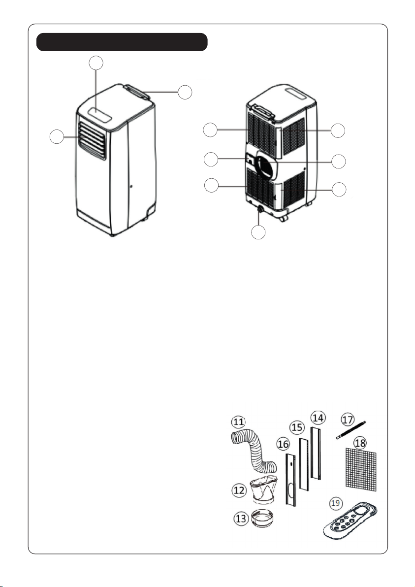
Components
1. Control panel
2. Carrying handle
3. Air outlet
4. Air lter
5. Exhaust air outlet
6. Air lter
7. Water stopper/
drainage point
8. Air inlet
9. Cord storage
10. Air inlet
Accessories
11. Exhaust hose
12. Flat Type Adaptor - for insertion over
hose & connected with PVC window kit
(or into hole in the wall/window).
13. I nward adaptor (connected unit &
exhaust hose)
14. PVC Window Kit 1 - for lling the open
window space
15. PVC Window Kit 2 - for lling the open
window space
16. PVC Window Kit 3 - for lling the
open window space and with hole for
connection to exhaust hose.
17. Drain tube for continuous drainage
18. Active carbon lter
19. Remote control
2
7
1
310
9
8
4
5
6

7
Installation
1. Offer the extendable slides to the window gap and adjust the length as you need.
2. Feed exhaust hose through the slide and slide window across so that spacer
is held securely. This technique may also be used for sash windows.
3. Note! Take care to maintain protection against intruders
Before using your air conditioner, you will need to install the exhaust hose so that
the heat (hot air) from the appliance are released onto an outside, open-air area.
To install the exhaust hose, feed the end of the hose through any available
window and secure it into place using the included adapter. Ensure the distance
between the unit and the window is at least 50cm.
To seal the gap around the adapter, you may utilize the extendable slides
(supplied along with the appliance) as below:
• Using the extendable slides
8
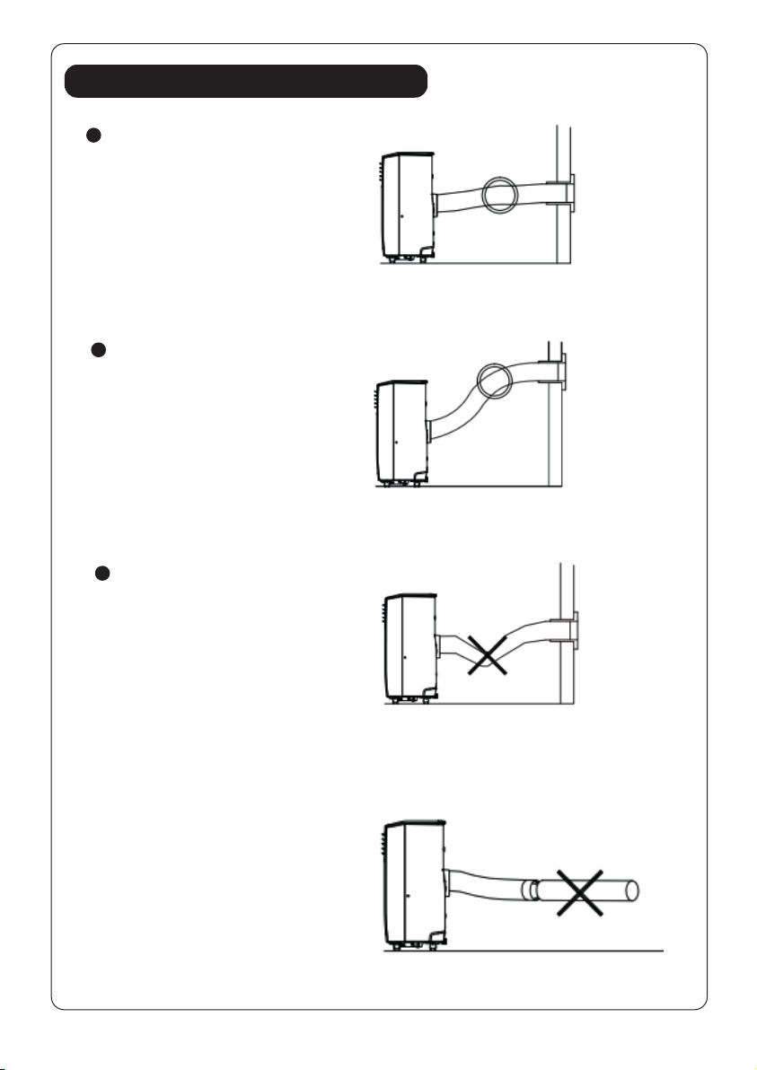
Mounting of the exhaust hose
Use only the hose provided
and attach exhaust hose
to the back of the air
conditioner.
FIG. 7
FIG. 10
WARNING!
The length of the exhaust hose
is specially designed according
to the specication of this
product. Do not replace or
extend it with an alternative
hose as this could cause the
unit to malfunction.
FIG. 9
The hose may be extended
from 300mm to 1500mm
but for maximum efciency
use the shortest length
possible.
FIG. 8
Avoid kinks and bends in
the exhaust hose as this will
cause expelled moist air to
build up causing the unit to
overheat and shut down.
Fig 7 & 8 show correct
position.

9
Installation of the carbon lter
1. Remove the lter frame from the unit.
2. Remove the active carbon lter from
its plastic bag.
3. Insert the active carbon lter into the
back of the unit.
4. Re-t the lter frame inside the unit.
FIG. 11
FIG. 12
10
Operation
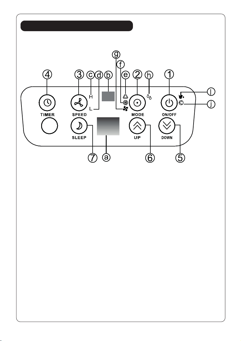
Control panel
1. ON/OFF (power) button
2. Mode (function) option
button
3. Speed (ventilation)button
4. “Timer” button
5. ‘Temperature down ‘ button
6. ‘Temperature up’ button
7. “Sleep” button
a. Display window
b. Receiver for remote control
c. High ventilation indicator
d. Low ventilation indicator
e. Automatic mode indicator
f. Cooling mode indicator
g. Fan mode indicator
h. DEHUMIDIFY(DRY) mode
indicator
i. “Full Water” indicator
j. Indicator for compressor
operation
Adjust the air vent
Before using the unit, please open the horizontal louvers. Adjust the louvers to
your desired direction.
FIG. 13

11
Turning ON/OFF
1. Press ON/OFF button, the unit will start in AUTO (automatic) mode.
Automatic mode
In automatic mode, the unit can cool or ventilate depending on ambient
temperature and setpoint adjustment. The unit is preset as follows:
If ambient temperature is above 23°C the unit is in automatic cooling mode
and is running according to the setpoint (Default setting 24°C). During this
operation, the indicators (LED) for AUTO & COOLING MODE illuminate
in green.
If the ambient temperature is less than or equal to (≤) 23°C, the unit is in
automatic ventilation mode. The indicators (LED) for AUTO & FAN MODE
illuminate in green.
Remark : For default setpoint 24°C , the unit starts to cool at 28°C (Setpoint
+ 4°C), when it cools down to 26°C (setpoint +2°C, it will then switch back
to ventilation mode.
2. The display window also shows the ambient room temperature from 0°C to
50°C.
3. To turn the unit off, press ON/OFF button again.

12
Setting mode/function
Press MODE button to select required working mode: automatic, cooling,
fan or dehumidify. The indicator of your selected mode is displayed.
Setting temperature
1. Press ‘Temperature up’ or ‘Temperature down’ button to regulate the
temperature desired.
2. The display window will show the temperature set as you press the
‘Temperature up’ or ‘Temperature down’ button. Otherwise, it will always
show the ambient temperature.
Setting ventilation speed
1. Press SPEED button to choose the ventilation speed desired, high or low.
The indicator for high or low ventilation will illuminate at the same time.
2. If the unit is in AUTO mode, it will choose the ventilation speed
automatically according to the ambient temperature (the related indicators
will illuminate), at this time, the speed switch is invalid.
Setting timer
1. Press TIMER button to set the operating hours desired (1 to 24 hours, the
timer indicator will illuminate). When the set time has been reached, the
machine will turn off automatically. The display window will show the hour(s)
set as the TIMER button is pressed. If the timer button is not pressed, the unit
will work continuously.
2. By pressing the timer but without turning on the other functions, you can
PRE-SET the time for the machine to operate. For example, if you press the
timer to ‘2’, the unit will work automatically after 2 hours.
Sleep function
1. In cooling mode, by pressing the SLEEP button, the set temperature will
increase 1°C (2°F) at the 1st hour, another 1°C (2°F) at the second hour,
then remains at that temperature.
2. In sleep mode, the ventilation will keep at low speed. Re-press the SLEEP
button, the setting temperature and ventilation speed will return to the
pre-selected one.

13
3. The unit will shut down automatically after the SLEEP function has been
running for 12 hours.
4. Please note, the sleep function is not available while the machine is working
in AUTO, FAN (ventilation) or DEHUMIDIFICATION mode.
5. When the machine is in the Sleep function, the Fan Speed is set at LOW
speed.
Dehumidify (DRY) mode
In dehumidify (DRY) mode, the temperature cannot be adjusted, the
ventilation will x at low speed. When the unit is operating in Dehumidify
(DRY) mode, humidity extracted from the air is collected in an internal tank.
If the tank reaches full, the compressor and motor cut out automatically.
At the same time, the “Water Full” indicator illuminates. An alarm will also
sound. When the tank is full, drain the water as shown on page 12.
You may also use the unit without having to empty the tank so often by using
“continuous drainage”, please also refer to page 12.
Self-diagnosis
This machine is equipped with a self-diagnosis function. If a fault develops, the
display window will display “E1” or “E2”. At this time, please contact Addvent
(0117 9235375).
All the above functions can also be performed
with the supplied remote control.
The remote control requires 2pcs
AAA batteries to operate (not included).
Important
1. To prolong the compressor’s life, after turning off the unit,
please wait for
3 minutes (at least) before turning back on.
2. The cooling system will switch off if the ambient temperature is lower than
the set one. The ventilation, however, keeps working on the set level. If the
ambient temperature rises above the selected level, the cooling will return
to operation.
FIG. 14
14
Drainage
During the process of cooling, some water will be extracted from the air into
the unit.
If the reservoir is full, both the compressor and motor will stop and the unit
will make an audible sound (you can press any button to stop the audible
sound). The W.F. indicator will also ash.
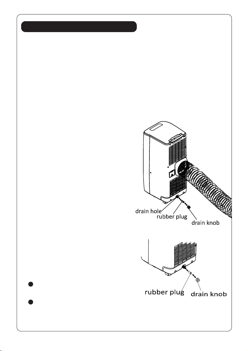
Please empty the water by one of the following methods:
1. Turn off the air conditioner and avoid
moving it when full.
2. Position a container (a water tray for
example) underneath the drain hole.
3. Remove the drain knob & rubber plug
from the drain hole and allow the water
to drain out.
4. When the container is almost full,
replace the rubber plug in the drain hole
and empty the water tray.
5. Repeat until the unit is emptied.
6. Replace the rubber plug and tighten
the drain knob rmly.
7. Switch on the unit - the water full or
compressor operating indicator should
not be ashing.
If you wish to operate the unit without
the need to empty the water tank, please:
Remove the drain knob and rubber
plug and retain for future use.
Connect the drain tube supplied to the water outlet as shown and locate
the other end into a drain.
FIG. 15
FIG. 16
15
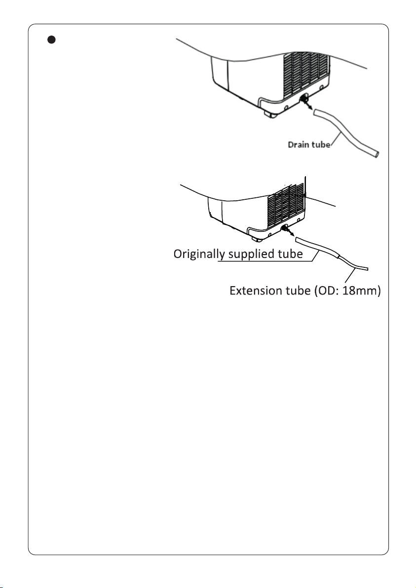
The drain tube may
be extended by adding
an extension tube and
using a suitable connector.
Please note
1. The drain must be at or
below the outlet level.
2. Flashing ‘full water’ indicator
will not function in this
mode of drainage.
3. If you want to extend the
water tube, you can
connect it with another
tube (OD: 18mm)
FIG. 17
FIG. 18
16
Maintenance
Always unplug the air conditioner from the mains before cleaning.
To maximize the efciency of the air conditioner, clean regularly.
Cleaning the housing
Use a soft, damp cloth to wipe the body clean.
Never use aggressive chemicals, gasoline, detergents, chemically treated cloths,
or other cleansing solutions.
Cleaning the lter
Use a vacuum cleaner or tap the lter lightly to remove loose dust and dirt
from the lters and then rinse thoroughly under running water (no hotter than
40°C).
Dry thoroughly before replacing.
Important: Never operate the unit without the lters.
End of season storage
Drain any water in the unit before completely operating the unit on
ventilation only mode for a few hours, to thoroughly dry the inside.
Clean or change the lter.
Unplug and store the power cord.
Replace in the original carton or cover for storage.

17
Fault Check List
The air conditioner does not run. Is the air conditioner plugged in?
Is there a power failure?
Is the ‘full water’ indicator ashing?
Is the room temperature below the
set temperature?
The air conditioner does not run Is the lter dirty, contaminated?
efciently. Is the air intake or output blocked?
Is the room temperature below the
selected temperature?
Are too many windows or doors
open?
Excessive noise. Is the machine positioned unevenly so
as to create vibration?
Is the oor underneath the machine
uneven?
The Air Conditioner compressor It is possible the overheat protection
doesn’t run. for the compressor is on. Please wait
for the temperature to drop.
Never try to repair or dismantle the unit yourself.
Telephone: 0117 244 8003 Fax: 0117 982 1554
Unit 12, Access 18, Bristol BS11 8HT
www.addvent.co.uk
ISSUE 2/1118
Waste electrical products should not be disposed of
with household waste. Please recycle where facilities
exist. Check with your local authority or retailer for
recycling advice.
Specication
Model no. AVAC9000
Power supply 220-240V~, 50Hz
Cooling capacity 9000BTU/ 2.6KW
Power/Ampere consumption 1000W/4.5A
Dehumidify capacity 24 L/day
Air Volume (max. speed) 360m
3
/h
Compressor rotary
Refrigerant R290
Fan speed 2
Timer 1~24 hours
Working temperature 18°C- 32°C
Exhaust hose Ø 142 x 1500 mm
N.W. 22 kg
Product size (W x D x H) 317 x 402 x 770 mm
WARRANTY
ONE YEAR
EXCHANGE
1
Other manuals for AVAC9000
1
Table of contents
Other Addvent Air Conditioner manuals


Popular Air Conditioner manuals by other brands


U-Line
U-Line H-5274 installation guide

Dometic
Dometic 620615.321 Installation & operating instructions

Trane
Trane SRUB Installation operation & maintenance

GE
GE ASTD5 and Owner's manual and installation instructions

TURBRO
TURBRO Finnmark FMP05AC user manual

Mitsubishi Electric
Mitsubishi Electric MSZ-SGH09VA operating instructions