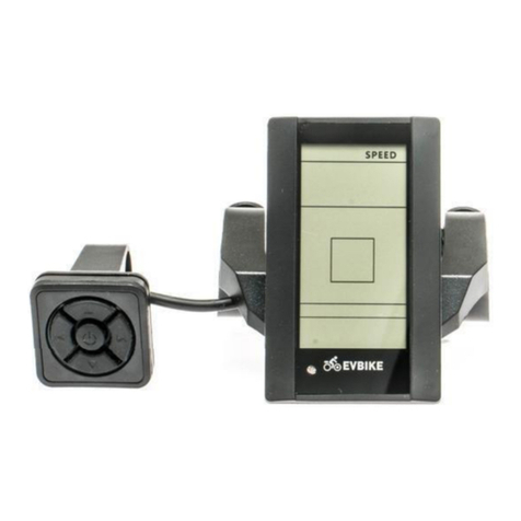
Adel System DPY351 User manual

DISPLAY DPY351
Monitor and Control Panel for ADELBus Network
Instruction Manual
Rev.:1
Table of Contents
1Product Description.............................................................. 2
1.1 Feature..................................................................................................................................................................................... 2
1.2 Monitoring................................................................................................................................................................................. 2
1.3 Configuration ............................................................................................................................................................................ 2
1.4 Alarms management................................................................................................................................................................. 2
1.5 History ...................................................................................................................................................................................... 2
1.6 Event ........................................................................................................................................................................................ 2
2ADELBus Connections......................................................... 2
2.1 Event based commands............................................................................................................................................................ 2
2.2 How to set up an ADELBus network ......................................................................................................................................... 2
2.3 Mains Technical Data................................................................................................................................................................ 2
2.4 Dimensions............................................................................................................................................................................... 2
3Installation............................................................................. 2
3.1 Panel Mounting......................................................................................................................................................................... 2
3.2 How to Supply DPY351............................................................................................................................................................. 2
3.3 Connection Layout (Fig.1)......................................................................................................................................................... 2
3.3.1 Auxiliary temperature sensor (AUX1) .............................................................................................................................. 3
3.3.2 Ethernet Connection (AUX2)........................................................................................................................................... 3
3.3.3 PowerBus Connection (AUX3) ........................................................................................................................................ 3
3.3.4 USB Connection (AUX4) ................................................................................................................................................. 3
3.3.5 Auxiliary Input Power (AUX5) .......................................................................................................................................... 3
3.3.6 Wire size (AUX5)............................................................................................................................................................. 3
3.3.7 Input/Output State Terminal 3,4,7,8 (AUX5) .................................................................................................................... 3
3.4 Ethernet Configuration.............................................................................................................................................................. 3
3.4.1 Accessing the HTTP server for the first time.................................................................................................................... 3
3.4.2 Customizing the ethernet interface and services.............................................................................................................. 3
3.4.3 Enabling / disabling the MQTT ........................................................................................................................................ 4
3.4.4 Saving / resetting the customized ethernet parameters ................................................................................................... 4
4Functional Use...................................................................... 4
4.1 Video Link:................................................................................................................................................................................ 4
5Welcome Page ...................................................................... 4
5.1 Notification / Alarm.................................................................................................................................................................... 4
5.2 Display Configuration “Homepage” ........................................................................................................................................... 4
5.3 Customize Dashboard............................................................................................................................................................... 4
5.4 Customize “Six Values”............................................................................................................................................................. 4
5.5 Customize “Two Values” ........................................................................................................................................................... 4
5.6 Customize “Single Value”.......................................................................................................................................................... 4
6Selection Page ...................................................................... 4
6.1 Monitoring................................................................................................................................................................................. 4
6.2 History ...................................................................................................................................................................................... 4
6.3 Alarms ...................................................................................................................................................................................... 4
6.4 Device “Advanced config –Pin insertion................................................................................................................................... 4
6.5 Devices “Add new devices”....................................................................................................................................................... 4
6.6 Display Configuration “Network menu” ...................................................................................................................................... 4

1 Product Description
The DPY351 is a robust and versatile multifunction display that
allows monitoring, configuring and managing the ADELSystem
devices connected in an ADELBus network. It is equipped with
a high-brightness and wide viewing-angle 3.5’’ TFT screen
which guarantees an optimum visibility in any operating
condition. The user interface is clear, intuitive and allows
configuring and managing ADELBus network through its
Ethernet interface by remotely monitoring connected devices,
using the SNMP and Modbus TCP protocols. The configuration
of the Ethernet connection is very straightforward and can be
done by means of the embeddedwebserver or the intuitive user
interface. The device IP addressing can be static or dynamic
using the DHCP protocol. This makes the connection of a
DPY351 to a LAN very easy. It is possible to connect several
devices in chain together, up to 50.
1.1 Feature
ADELBus network manages all the connected devices.
1.2 Monitoring
It is possible the monitoring of the input and output data, peak
current, peak voltage, all the battery parameters such as
temperature, State of Charge, etc.…
1.3 Configuration
With the DPY351, it is possible to modify the parameters of any
ADELsystem device connected: DC Ups, Power Supply and
Battery Charger.
1.4 Alarms management
All the alarms present on the single device are immediately
reported.
1.5 History
The history parameters are recorded inside each device. The
DPY351 allows inspecting all the historical parameters of each
single device.
1.6 Event
Actions that are coordinated among the devices connected can
be programmed, thus automating the system.
2 ADELBus Connections
ADELBus is the ADELSystem network to interconnect the
devices via Modbus and Canbus protocols.
ADELBus is used as power management system for all
connected equipment, such as the DC-Ups, battery charger,
power supply.Every compatible device with ADELBus is
equipped with one or two data ports. The devices are simply
chained together, forming a local data network. Monitoring
panels such as the DPY351 can be used for monitoring and
control all connected ADELBus equipment.
CAUTION: Never connect a non ADELBus device to the
ADELBus network directly! This will void warranty of all
ADELBus devices connected.
2.1 Event based commands
With ADELBus, a device can be programmed to initiate an
action at another connected device. This is done by means of
event-based commands.
2.2 How to set up an ADELBus network
Connections between the devices are made by standard
straight ADELBus cables. ADELSystem can supply these
cables. These (CAT5) cables are also commonly available at
computer supply stores. For the Can Connection in some
devices it is usual use twisted pair cable with shield.
Up to 50 ADELBus devices can be connected together.
The electric power for the network comes from the connected
devices. Otherwise, if it is not enough it is necessary to connect
the device by + and –connector AUX5.
ADELBus needs a terminating impedance on both ends of the
network, for that it is present a switch termination on the Device.
2.3 Mains Technical Data
Type
DPY351
Weight
0,25 kg.
0.55 lbs.
Dimension
112 x 116 x 53 mm
4,41 x 4,57 x 2,09 inches
Dimension Display
90 mm; 3,5 inches
Languages
EN
IP Degree
Front: IP65
Back: IP20
Power Supply
PowerBus/ 12/24/48 Vdc input
Power Consumption
Sleep 0,06 W
Normal Mode: 3.6 W
2.4 Dimensions
3 Installation
3.1 Panel Mounting
It is possible to mount DPY351 through a 90mm hole on the
Panel and fixthem by 4 2.9 x16. No limit for thePanel thickness.
3.2 How to Supply DPY351
The DPY351 can be powered from the ADELBus network.
There must be ADELBus (AUX3) powering devices available to
provide sufficient power to the network. If there is no ADELBus
powering device or the available power is not sufficient, the
DPY351 must be connected to a 12/24/48 V battery or Output
Load via the supplied connector (AUX5).
3.3 Connection Layout (Fig.1)
1234
56

Reference
Description
1
Temperature Probe (AUX1)
2
Ethernet (AUX2)
3
ADELBus: Canbus, ModBus (AUX3)
4
USB (AUX4)
5
Auxiliary Power, I/O port (AUX5)
6
Dip-switches (Hardware Config.)
3.3.1 Auxiliary temperature sensor (AUX1)
Auxiliary temperature sensor connection (RJtemp accessory
probe) to measure the temperature environment in custom
situations.
3.3.2 Ethernet Connection (AUX2)
"HUB" Collector function of the connected devices to the
ADELBus network, to transport via Ethernet. The available
protocols are the Modbus TCP / IP, the SNMP protocol and the
MQTT.
3.3.3 PowerBus Connection (AUX3)
Automated RJ45 cable connection for Modbus and Canbus
protocols. The Display must be powered via the Aux5 connector
If the power is not enough.
3.3.4 USB Connection (AUX4)
USB Connection for Software Updates via PC.
3.3.5 Auxiliary Input Power (AUX5)
Connect the positive wire to terminal 1, the negative wire to
terminal 2 of the connector.
Use a 3mm flat blade screw driver to push in the Spring
Connector.
3.3.6 Wire size (AUX5)
Use appropriate wire size to connect the AUX power supply to
the battery.
- Wire diameter Ø 1 mm (18AWG) 2.5 mm (13AWG)
- Fuse: Insert a 1A fuse in the positive battery line.
3.3.7 Automatic Power On Display
(Aux6)
The device power ON in manual Condition from Push
Button power On, otherwise canstart up inAutomatic
Power On. For this function set Switch 4 in position
On
3.3.8 Input/Output State Terminal 3,4,7,8 (AUX5)
The device is equipped with N°2 digital Input (terminal 3,4)
suitable to reading conditions. They can be used for the most
various checks. For example: the control of opening doors,
presence of Earth, verification of presence Light, gas, pressure,
etc...
The Output relay (terminal 7,8) could be drived in dependency
of input state by “Event” function.
- Output Relay Free Switch Contact (NO)
Max. current can be switched (EN60947.4.1):
Max. DC1: 30 Vdc 1 A; AC1: 60 Vac 1A
Min.1mA at 5 Vdc (Min Resistive load)
3.4 Ethernet Configuration
Configuration of the Ethernet interface by HTTP server viaWeb
browser:
3.4.1 Connect HTTP server for the first time
The first access to the DPY351internal webserver must be done
by means of a browser at the DPY351 factory-default IP
address, which is 192.168.1.100 using a standard CAT5e or
higher LAN cable connected to the AUX2 connector (RJ45,
shielded) onthe back of the unit, as shown in Fig.1. First access
must be done at standard HTTP port, port number 80; please
make sure that this port is avaible. Type http://192.168.1.100
into any browser’s address bar.
At the login page, the following details must be used:
Username: admin
Password: admin
3.4.2 Customizing the ethernet interface and
services
In the setup page the following groups of parameters are
displayed:
•Account
•TCP/IP Configuration
•SNMP v2c
•MQTT
Account:The Account group (Fig. 2) allows the customization
of the data for the HTTP server login page.
Fig. 2 –Account settings
TCP/IP Configuration
Fig. 3 shows the TCP/IP Configuration group of parameter
default values. They allow unique identification of the unit in the
network.
Fig. 3 –IP settings
If “Dynamic (DHCP)” is selected, the IP address is automatically
assigned by a DHCP server, that must be active on the network,
and the System IP, Subnet Mask and Gateway textboxes are
not available.
HTTP Port allows redirecting the HTTP traffic to a port different
than the TCP port 80, which is the one devoted to HTTP. In the
case “HTTP Port” checkbox is not selected, the HTTP protocol
will be run on port 80 and the “HTTP Port” textbox will be hidden.
If “HTTP Port” checkbox is selected, then the “HTTP Port”
textbox should be populated with the TCP port number the
HTTP traffic must be redirected to. In such a case, access to the

HTTP server from a browser must be made according to the
following syntax: http://ipaddress:portnumber.
As an example, if the IP address is 192.168.1.100 and the
selected HTTP port is 5678 then the following IP string should
be entered in the browser
http://192.168.1.100:5678
The DPY351 supports access using the Virtual LAN protocol. In
the case “VLAN ID” checkbox is not selected the “VLAN ID”
textbox will be hidden and DPY351 will not operate in the VLAN.
If “VLAN ID” checkbox is selected then the “VLAN ID” textbox
should be populated with the ID. The VLAN ID can be set in the
range 1 thru 4094 and it must match that of the VLAN the unit
is operating in.
SNMP v2c
The DPY351 can act as a gateway between an ADELsystem
power device (such as the CBI Size 3 and 4) and a SNMP
manager. An ADELsystem MIB table is provided which consists
of a list of parameters of the connected power device that can
be remotely read, or read-written through the SNMP. Each
parameter, (OID), is mapped one-to-one to a Modbus RTU
holding register. Refer to the document
CBIxxxW_Modbus_SNMP_MAP_Revx_y.pdf for the
description of each RTU holding re gister and the corresponding
OID.
Fig. 4 –SNMP settings
All the fields in the SNMP group of settings allow a maximum of
32 characters, except “System Description” and “System
Location”, which allow 255 characters maximum. The “Read-
only community” and “Read-write community” values must
match those of the SNMP environment the unit operates in.
3.4.3 Enabling / disabling the MQTT
MQTT communication allows the DPY351 to connect to the
ADELView System Cloud for the remote monitoring of the
power devices connected to the DPY using Modbus or CAN
bus. It can be enabled or disabled by respectively checking or
unchecking the MQTT radio button. Communication using the
MQTT protocol is enabled by default.
3.4.4 Saving / resetting the customized ethernet
parameters
To save the changes into the DPY351 non volatile memory
press the “Apply” button at the top or at the bottom of the page.
Changes will take effect at the following DPY351 power up.
To clear all the ethernet parameters press the “Reset” button,
then re-enter the data.
4 Functional Use
4.1 Video Link:
https://www.youtube.com/watch?v=hy4V7s5XCQg
Short Version (https://goo.gl/R56vkY)
5 Welcome Page
5.1 Notification / Alarm
(Link to Video Explanation)
(https://www.youtube.com/watch?v=hy4V7s5XCQg&t=10s)
5.2 Display Configuration “Homepage”
(https://www.youtube.com/watch?v=hy4V7s5XCQg&t=193s)
5.3 Customize Dashboard
(https://www.youtube.com/watch?v=hy4V7s5XCQg&t=207s)
5.4 Customize “Six Values”
(https://www.youtube.com/watch?v=hy4V7s5XCQg&t=245s)
5.5 Customize “Two Values”
(https://www.youtube.com/watch?v=hy4V7s5XCQg&t=296s)
5.6 Customize “Single Value”
(https://www.youtube.com/watch?v=hy4V7s5XCQg&t=323s)
6 Selection Page
6.1 Monitoring
(Link to Video Explanation)
(https://www.youtube.com/watch?v=hy4V7s5XCQg&t=35s)
6.2 History
(https://www.youtube.com/watch?v=hy4V7s5XCQg&t=57s)
6.3 Alarms
(https://www.youtube.com/watch?v=hy4V7s5XCQg&t=85s)
6.4 Device “Advanced config –Pin insertion
(https://www.youtube.com/watch?v=hy4V7s5XCQg&t=100s)
6.5 Devices “Add new devices”
(https://www.youtube.com/watch?v=hy4V7s5XCQg&t=136s)
6.6 Display Configuration “Network menu”
(https://www.youtube.com/watch?v=hy4V7s5XCQg&t=169s)
Menu
Back
Power On
Save
Clear
Select
Alarm
Edit
>
Select
<
Back
