D. A stand-alone keyswitch cannot be used for ON-OFF control of the panel when the No. 21612 is used
with an alarm processing center.
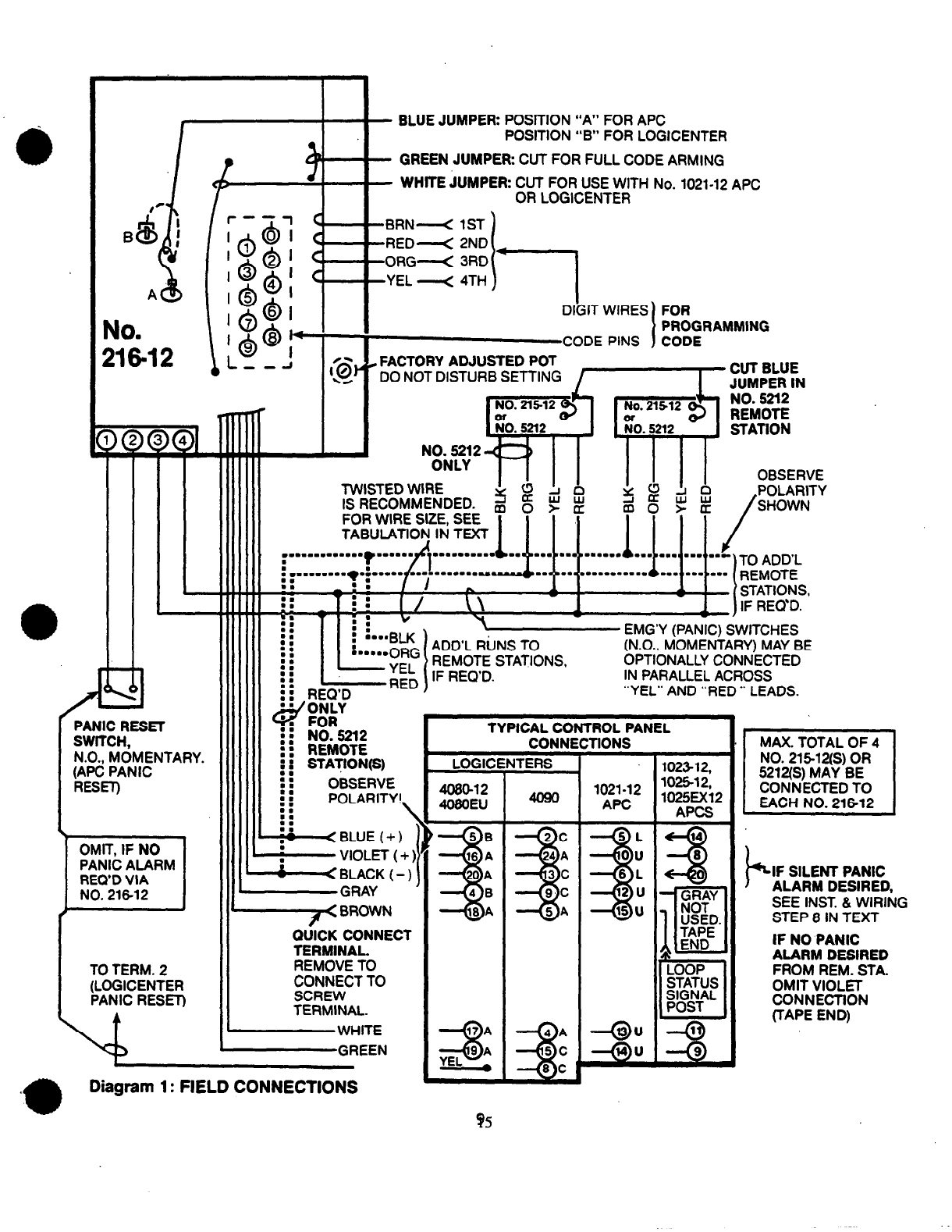
INSTALLATION AND WIRING (See Diagram 1): ?
Up to four No. 21512 or 5212 Remote Stations may be connected to the No. 21612 in partillel indoors, on one or -’
more wire runs originating at the control (where the No. 21612 will be located).
The wire size to be used for the entire length of a wire run depends upon the distance from the control to the
farthest remote station on that particular run. Use the following tabulation to determine the wire size(s)needed
for the proposed run(s).Twisted pair is recommended for greater immunity to unwanted induced voltages.
MAXIMUM DISTANCE TO WiRE ADEMCO NO. (TWISTEDPAIR)
FARTHESTREMOTESTATION SfZE to No. 21512 to No. 5212
100feet #22 No. 289 2 No. 289’
I
500
I
#18#16
#20 I
No.No.No. 283284282 222 No.No.No. 283284282 I
l
Alternatively, No. 295(4conductor) cable can be used.
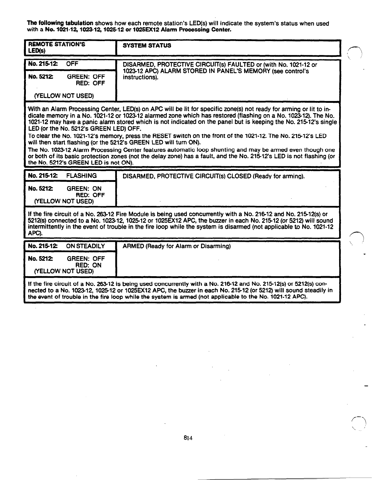
If a’No. 102512 or 1025EX12Alarm Processing Center is being used, the remote station used at opening time
should be located so that the ALARM MEMORY LED on the the alarm processing center can be viewed at open-
ing time before the panel is disarmed (this LEDwill be lit if an alarm has taken place during the armed period).
(Not relevant to other controls shown, as they have alarm memory by zone after disarming.)
IMPORTANT: Locate the remote station(s) where the buttons are not likely to be depressed accidently, as this
could lead to spurious am\ing (if single digit QUICK ARM is used)or false panic alarms.
An emergency (panic) alarm can be triggered at any No. 2l512 or 5212 Remote Station by momentarily pressing
its buttons marked # and l simultaneously.
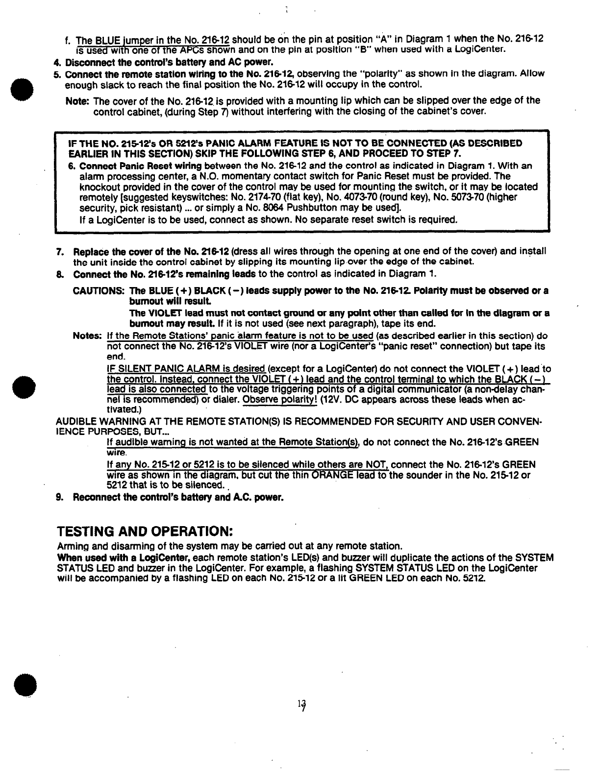
Note: If use of this feature is not desired, the No. 216-12’sVIOLET lead may be left disconnected from the con-
trol unit during installation. See Step 8 in the following procedure.
Locate the Remote Station(s) and run the wiring between them and the control as described above. Connect
each remote station’s leads as shown in Diagram 1. Connections to the No. 21612 Adapter (to be installed
within the control) will be made later. In each No. 5212 Remote Station used, CUT THE BLUE JUMPER.
If desired, connect any number of momentary type N.O. emergency (panic) switches (e.g.:No. 21.8)across the
“RED” and “YEL”
N(S)
to the remote station(s).
Note: If the Remote Stations’ panic alarm feature is not to beconnected as described earlier) emergency
(panic) switches may onl be connected on separate wiring to the control panel, in the standard man-
ner, for audible panic a amr or directly to a digitalcommunicator if SILENT PANIC ALARM is used (see-F
WIRING Step 8).
,f-
,, ,
‘.
Remove the cover from the No. 21812 Adapter (grasp the cover at the.wiring opening and pull firmly) and pro
gram its PC board as follows:
a. Select a four digit “disarm” code. The code may consist of any 4 different digits from 0 to 9 (e.g.:2 15 8).
Codes containing repeated digits (such as: 4 3 3 7 or 6 5 4 6)cannot be used.
b. Place the four “digit wires” on the appropriate “code pins”. The BROWN “digit wire” should be placed on
the “code pin” corresponding to the first digit in the selected code (e.g.:Pin 2, if 2 15 8 is the selected
code). Similarly, the RED, ORANGE, and YELLOW wires should be placed on the pins corresponding to the
2n.d 3rd and 4th digits respectively. All four “digit wires” must be connected for proper operation.
c. Full four digit ARMING may be desired as well. me system normally will arm upon the pressing of only the
first digit of the programmed four digit disarm code at a No. 21512 or 5212 Remote Station. (This is par-
ticularly useful if the system will normally be armed by personnel not authorized to have knowledge of the
full four digit disarm code.)
If, however, full four digit ARMING is desired, cut and remove the 2” GREEN jumper from the No. 21612
circuit board. The system will then require the full four digit code to be pressed before arming takes place.
d. If a LogiCenter or No. 1021-12APC is being used, cut the 4” “WHITE” jumper on the PC board and tape the
cut ends.
e. DO NOT DISTURBTHE FACTORY ADJUSTED POTENTIOMETERON THE No. .216-12’sPC BOARD.
6
12