ADEMCO 5216 User manual

for No. 215 Two Wire Digital Remote Stations with Panic
(for Indoor use only)
GENERAL INFORMATION:
The No. 5216 Adapter and No. 215 Two Wire Digital Remote Station(s) with Panic
Circuitry permit 4 digit coded pushbutton ON/OFF (Arm/Disarm) Control of the
Nos. 1023 and 1024 Alarm Processing Centers and all combination burglar/fire
controls in the Nos. 330R, 332R, 340R and 342R series. In‘addition, keyed shunting
can be applied (or removed) at a No. 215 Remote Station, at any time, to a single
zone or to shut-off space protection devices within a zone, by depressing appro-
priate key combinations on the No. 2.15 (although any manual or automatic zone
shunting applied by the control takes priority).
No. 215’s are for indoor use only. When used with a control without entry/exit
delay (such as a No. 330R or 340R) a suitable outdoor remote station (such as
No. 246, 246R or 5246) should’be installed as well, to control entry/exit.
DESCRIPTION:
Only two wires are required to connect up to four No. 215 Remote Stations to the
No. 5216 Adapter. A twelve pushbutton keypad on each No. 215 enables the user to
arm or disarm the control, initiate a panic alarm at any time, shunt a single
protection zone or directly and selectively shut off space protection devices
within a zone. Status of the control’s burglar alarm circuit(s) (such as: “not
ready for’ arming”, “alarm memory”, “ready for arming”, “keyed shunt” or “armed”)
is indicated by a single LED on each No. 215. An audible warning indicator is
built into each No. 215 for use with those controls having entry/exit delay
circuits and for other system warning sounds as the control or
may provide (see instructions accompanying-those units).
If desired, momentary type normally open emergency (panic) swi t
may be connected across the remote stations’ two wi re ci rcuit
separately wired to the panel (unless the remote stations’ pan
is not to- be connected, &s descri bed in t he INSTALLATION AND W
ches (e.g.: No. 219)
nstead of switches
c alarm feature
RING Section).
A “S I LENT PAN IC ALARM” connect ion option can be used, which utilizes the No. 5216’s
panic circui-try to trip a digital commun cator (e.g. : No. 669 or No. 670) or dialer
(e.g. : No. 612). A silent alarm can then be transmitted to a remote location when the
appropriate pair of buttons on a No. 215 Remote Station (or a panic switch connected
across its two wire circuit) is pressed. The special connections required are incor-
its accessories
porated in the INSTALLATION AND WIRING Section herein.
The.No. 5216 Adapter’s housing is designed to clip into the cabinet of the.aIarm control
with which it is used. It contains a PC board which includes: a) Leads for alarm
control connections, b) “Digit Wires” and “Code Pins” for programcthe 4 digit code,
c) Jumpers for cutting or positioning, as required, and d) Terminals for “Panic
Reset” and No. 215 connections.
No tamper switches are needed in the No. 215 Remote Station as the system is inherently
secure. A full four digit code is required to arm or disarm the system and that code
648
www.PDF-Zoo.com

cannot be determined at any remote station.
between the stations’ A.short or even momentary low resistance
two wi’re run at any time will initiate a panic alarm (unless’
) the panic feature is not to be connected, as described later).
4D Notes : A. Only No. 215 Remote Stations (up to 4) may be used with the No. 5216
Adapter.
B. Circuit safeguards will prevent arming or disarming by erasing al!
prior information entered via the keypad if: a) an erroneous digit
is entered or, b) more than approximately 3 seconds are taken to
enter the code.
. C. Other remote stations (e.g.: Nos. 214, 218R, 246, 246R, 5246) and
(where required) the No. 247 Adapter may be simultaneously, but
independently, connected to controls in the Nos. 330R, 332R, 340R
and 342R series. As many “other” remote stations may be used as
would otherwise be allowable without the No. 5216.
D. When a No. 5216 is used with a No. 1023 or 1024 Alarm Processing
Center, a stand-alone keyswitch cannot be used for ON-OFF control
of the panel.
INSTALLATION AND WlRlNG(See Diagram 1):
Up to four No. 215 Remote Stations may be connected to the No. 5216 in parallel,
indoors on one or more two wire runs originating at the control (where the No.
5216 wili be located).
The wire .size to be used for the entire length of a two wire run depends upon the
distance from the control to the farthest remote station on that particular run.
Use the following tabulation to determine the wire size(s) needed for the proposed
run(s). Twisted pair is recommended for greater immunity to unwanted induced voltaqes.
MAXIMUM DISTANCE TO
FARTHEST REMOTE STATION
IO0 feet
200
300
500
WIRE ADEMCO NO.
SIZE (TWISTED PAIR)
#22 289
#20 283
#I8 284
#I6 282
If. a No. 1024 Alarm Processing Center is being used, the remote station used at
opening time should be located so that the ALARM MEMORY LED on the alarm processing
center can be viewed, at opening time before the.peneI is disarmed (this LED will
be lit if an alarm has taken place during the armed period). (Not relevant to No.
1023, which has alarm memory by zone after disarming.)
An emergency (panic) alarm can be triggered at any No. 215 Remote Station by momen-
tarily pressing its buttons marked # and * simultaneously.
Note : If this feature is not desired, the No. 5216’s VIOLET lead may be
left disconnected from the control unit during installation. See
Step 8 in the following procedure.
649
www.PDF-Zoo.com

-QU
I
CK CONNECT TERM
INALS PROVIDED
REMOVE WHEN CONNECTING TO SCREWTERMINALS
TYPICAL CONTROL PANEL
CONNECTIONS
I
.
.*
.
-IF SILENT PANIC ALARM DESIRED. SEE INSTALLATlObi
330R
340R
SERIES
023,1024
A?C’s
332R
342R
SERIES \ -
AND WIRING STEP 8 IN TEXT.
BLUE(+) ’
VIOLET(+)
BLACK(-)
GRAY
BROWN
\’ T
/
/
s
‘POSITION B (FOR-
OTHER APPLICA -
TIONS)
POSITION A (NOR- -
MAL, FOR CONTROL!
SHOWN)
WHITE
-1
JUMPERS
li
0
21
o--
20
o--
19
o-
15
o-
14
=(3rd
x(4th PROGRAMMING
-
-
FACTORY ADJUSTED POTENTIOMETER.
‘DO NOT DISTURB SETTING.
’ QREEN
-1
1 1
1 GREEN! ,-TERM INAL BLOCK
TO NO. 5216 TERM. 2
PANIC RESET SWITCH, N.O. MOMENTARY FOR KEYED SHUNTING,’
(REo’D ONLY FOR AUDIBLE PANIC ALARM SEE DIAGRAM ?
WITH APC, OR SILENT PANIC ALARM
WITH .4PC OR 330R-342R SERIES CONTROL).
WIRE SIZE TO REMOTE STATIONS DEPENDS
ON DI STANCE TO FARTHEST STAT ION (SEE
TABULATION IN TEXT).
EMERGENCY (PANIC) SWITCHES (N.O.,
MOMENTARY), IF USED, MAY BE CONNECTED
IN PARALLEL ACROSS THESE LEADS.
MAXIMUM TOTAL OF 4 NO. 215’s MAY
BE USED WITH EACH NO. 5216.
*OMIT IF NO PANIC ALARM IS DESIRED FROM NO. 215’s.
#CONNECTIZ REQ’D ONLY FOR AUDIBLE PANIC ALARM.
--.
: ) ,_._
‘I.._. ‘I
‘I._ ”-1
‘,..-
www.PDF-Zoo.com

‘1. \
I .
2.
3.
4.
5.
Locate the No. 215 Remote Station(s) and run the two wire circuit(s) between them
and the control as described above. Connect the remote station RED and YELLOW
leads across the “A” and “8” leads respactively, as shown in Diagram I. Connections
to the No. 5216 Adapter (to be installed within the control 1 wi I I be made later.
IMPORTANT: Locate the No. 215,(s) where the buttons are not Ii kely to be depressed
accidently, as this could lead to false panic alarms.
If desired, connect any number of momentary type N.O. emergency (panic) switches
(e.g. : No. 219) across the two wire run(s) to the remote station(s).
Note : If the No. 215 Remote Stations’ panic alarm feature is not to be
connected (as described earlier), emergency (panic) switches may
on ly be connected on separate wi ri ng to the contra I pane I, in the
standard manner for audible panic alarm or directly to a digital
communicator if SILENT PANIC ALARM is desired (see WIRING Step 8).
pemove
and pull gently) and program the PC board as follows:
a. Select a four digit “arm/disarm” code. The code may consist of any 4
different digits from 0 to 9 (e.g.: 2 I 5 8). Codes containing repeated
digits (such as: 4 3 3 7 or 6 5 4 6) cannot be used.
b. Place the four “digit.wires” on the appropriate “code pins”. The BROWN
“digit wire” should be placed on the “code pin” corresponding to the first
digit in the selected code (e.g.: Pin 2, if 2 I 5 8 is the selected code).
Similarly, the RED, ORANGE’and YELLOW wires should be placed on the pins
corresponding to the 2nd, 3rd and 4th digits respectively. All four
“digit wires” must be connected for proper operation.
C.
If a control in the No. 330R to 342R Series is being used, cut the 4”
WHITE and 2” VIOLET jumpers on the PC board and tape the cut ends. (Caution‘:
Do not cut the VIOLET jumper if a SILENT PANIC ALARM is to be connected.)
If a No. 1023 or 1024 Alarm Processing Center is used, the WHITE and
VIOLET jumpers should never be cut.
d. DO NOT DISTURB THE FACTORY ADJUSTED POTENTIOMETER ON THE NO. 5216’s PC BOARD.
e. The BLUE jumper should be on the pin at position A in Diagram I when the No.
5216 is used with any of the controls shown. Position B is for other applications
(described elsewhere).
Disconnect the control’s battery and AC power.
Connect the remote station wiring to terminals 3 and 4 of the No. 5216, observing
the “polarity” shown in the diagram. Allow enough slack to reach the final position
the No. 5216 will occupy in the control.
Note :
The cover of the No. 5216 is provided with a mounting lip which can be
slipped over the edge of the control cabinet, (during Step 7) without
interfering with the closing of the cabinet’s cover.
757
651
www.PDF-Zoo.com

IF THE NO. 215’s PANIC ALARM FEATURE IS NOT TO BE CONNECTED (AS DESCRIBED EARLIER
IN THIS SECTION) SKIP THE FOLLOWING STEP 6, AND PROCEED TO STEP 7.
6. Connect Panic Reset wiring between the No. 5216 and the control (or separate reset
switch) as indicated in Diagram I.
Note: If a No. 1023 or 1024 Alarm Processing Center is to be used with audible
panic alarm (or if SILENT PANIC ALARM is to be used with an APC or a No.
330R-342R Series control) a N.O. momentary contact switch for Panic Reset
must be provided. The knockout provided in the cover of the No. 1023 or
1024 may be used for mounting the switch,
[suggested keysw i tches: or it may be located remotely
No. 2 174-70 (f I at key 1, No.’ 4073-70 (round key),
No. 5073-70 (higher security, pick resistant)...or simply a No. 8064
Pushbutton may be used].
7. Replace the cover of the No. 5216 (dress all wires through the opening at one
end of the cover) and instal I the unit inside the control cabinet by slipping
its mounting lip over the edge of the cabinet.
8. Connect the No. 5216’s remainingleads (for the RED, YELLOW and ORANGE keyed
--we --- _~_
shunting leads see Step 9) .-to the control as indicated in Diagram I.
CAUTIONS: The BLUE(+) and BLACK(-) leads supply power to the No. 5216. Polarity
must be observed or a burnout will result.
The VIOLET lead must not contact ground or any point, other than
called for in the diagram, or a burnout may result. If it is not
used (see next paragraph), tape its end.
::otes: *
If the No. 215 Remote Stations’ panic alarm feature is not to be
connected (as described earlier in this section) do not connect the
No. 5216’s VIOLET wire, but tape its end.
If SILENT PANIC ALAR?1 is desired, do not connect the VIOLET (+I lead
to the control . Instead, connect the VIOLET (+I lead and the control
terminal to which the BLACK (-1 lead is connected, to the voltage
triggering points of a digital communicator (a non-delay channel
is recommended) or dialer. Observe polarity! (6V. DC appears across
these leads when activated.)
If a control with entry/exit delay is used, audible warning is
recommended for security and user convenience, but...
If audible warning is undesirable at the
No.
215 Remote Station(s),
do not connect the No. 5216’s GREEN wire.
If any one No. 215 is to be silenced while others are not, connect
the No. 5216’s GREEN wire as shown in the diagram, but cut the thin
ORANGE lead to the sounder in the No. 215 that is to be silenced.
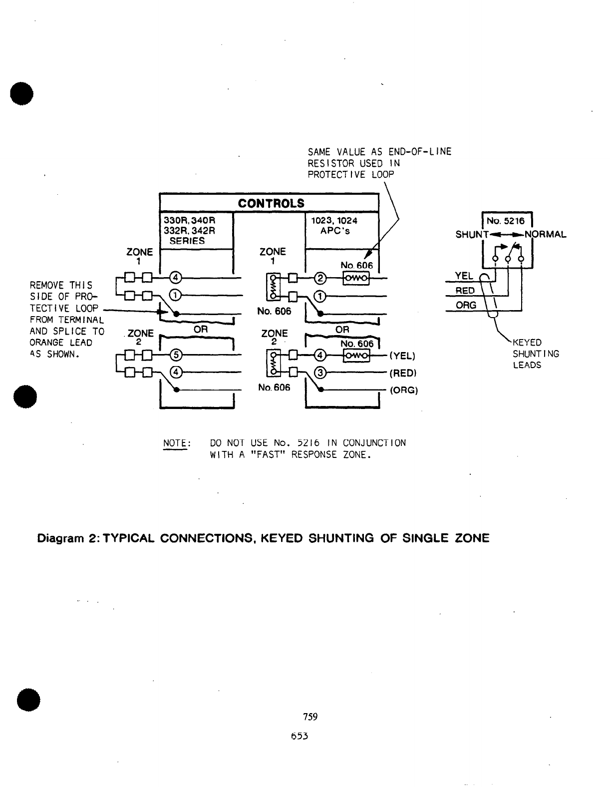
9. If the No. 5216’s keyed shunting feature is to be used, connect the unit’s RED,
YELLOW and ORANGE keyed shunting leads to a single zone in the control as indicated
in Diagram 2, or to space protection devices as indicated in Diagram 3.
Notes: Do not use the No, 5216’s keyed shunting feature in ‘conjunction with
a “fast response” zone (to avoid possible detection of the brief opening
of the keyed shunting relay
Contacts
as they operate). f? *I
758
652
www.PDF-Zoo.com

(YEL)
(RED)
(ORG)
NOTE: DO NOT USE No. 5216 IN CONJUNCTION
WITH A “FAST” RESPONSE ZONE.
\ KEYED
SHUNTING
LEADS
SAME VALUE AS END-OF-LINE
RESISTOR USED IN
PROTECTIVE LOOP
CONTROLS
REMOVE THIS
SIDE OF PRO-
TECTIVE LOOP
FROM TERMINAL
AND SPLICE TO
ORANGE LEAD
4s SHOWN.
Diagram 2: TYPICAL CONNECTIONS, KEYED SHUNTING OF SINGLE ZONE
759
653
www.PDF-Zoo.com

330R, 340R.
332R, 342R
SERlES
BATT.
PACK
1023,1024
APC’s
TO SWITCHED (+ 6V)
CONTROL SIGNAL TERMINAL
OR POST IN DETECTOR(S)
KEYED
SHUNT
(SHUT-OFF) -NORMAL
I I I
I
I f’ an opt iona 1, detector
operating mode is used,
connect the switched
CONTROL SIGNAL voltage
here, i nstead of di -
TO BE SHUNTED 1-r rectly to detector(s).
I
450, 454, 750, 754 GND
ULTRASONIC: 450-6, 454-6, 750-6, 754-6 DC(- &As +
PASSIVE IR: 650, 651, 650-6, 651-6 +
MICROWAVE: 850, 851, 852 +
SHUT-OFF: +6V
ACTIVE: OV
Diagram 3: TYPICAL CONNECTIONS, KEYED SHUNTING (SHUTOFF) OF SPACE
PROTECTION DEVICES
760
654
www.PDF-Zoo.com

If an end-ofiline resistor is normally used in a zone selected for
keyed shunting, a similar resistor must be connected in series with
the No. 5216’s YELLOW lead as shown.
A keyed shunt connected to a space protection device will lock the
detector in its “standby” state and keep its .a larm contacts from operating’
as long as the shunt is in effect. With ultrasonic detectors (such as
those in the Nos. 450, 454, 750 and 754 series) which have one of their
transmitter day shut-off options selected, the power to the transmitters
will be off while a keyed shunt is in effect.
IO. Reconnect the control’s battery
and
A.C. power.
TESTING AND OPERATION:
Arming and disarming of the system and (if used) keyed shunting may be carried out
at any remote station.
The following tabulation shows how each remote stations’ LED will indicate the system’s
status when used with a No. 1023 or 1024 APC or a control in the 330R, 332R, 340R
or 342R series.
LED ON No. 215 SYSTEM STATUS: No. 1023 or 1024 APC or No.
33OR, 332R, 340R, or 342R SERIES CONTROL
OFF
I
DISARMED, PROTECTIVE CIRCUIT(S) OPEN or (with
No. IO231 .4LARM STORED IN PANEL’S MEMORY (see
control’s instructions) I
LED’s on Alarm Processing Center will be lit for specific zone(s) not
ready for arming (or flashing for memory ina No. 1023 alarmed zone which
has restored. If No. 1023’s LED is flashing, system may be armed directly
witho’ut any loss of protection. To clear panel’s memory and restore
flashing condition to remote station LEDs, arm and immediately disarm
the system. 1
FLASHING (NO
I
BUZZER)
I
DISARMED, PROTECTIVE CIRCU.IT(S)
OFF more than ON CLOSED (Ready foi Arming)
The Nos. IO23 and IO24 Alarm Processing Centers feature automatic
loop shunting and may be armed even though one or both of their
basic protection zones (not the delay zone) has a fault, and the
remote station LED is no-lashing (automatic loop shunting may
be optionally disabled in the No. 1024).
If the fire circuit of a No. 245 Adapter is being used concurrently
with a No. 5216 and 215(s) (for arming/disarming) connected to a No.
1023 or 1024 APC, the buzzer in each No. 215 will sound intermittently
in the event of trouble in the fire loop.
FLASHING (NO BUZZER) ARMED (Keyed Shunting by No. 5216
ON more than DFF in Effect)
ON STEADILY ARMED (Ready for Alarm or Disarming)
655
www.PDF-Zoo.com

For details of operation with other controls, see the instructions that accompany the
particular controls.
I. Arm and disarm the system at each remote station and check the response of each
station’s LED indicator (see Note B on page 2):
a. Make sure all protective circuits are closed and system is ready for arming
(remote station LED should be flashing, more OFF than ON).
b. Arm the system by entering the 4 digit code at the remote station (the
remote station LED should light steadily).
If a basic protection circuit (without entry/exit delay) is disturbed, an
alarm wi I I sound immediately.
If an entry/exit delay circuit is disturbed, the remote station’s audible
indicator will sound during the “entry delay” period. If the system is not
disarmed before the entry delay period expires, an alarm wi I I result.
For buzzer warnings that occur during other than normal arming conditions,
see the instructions that accompany the control.
c. Disarm the system .by entering the entire 4 digit code at the remote station
(the station’s LED should go off or start flashing, more OFF than ON).
2. If the No. 5216’s keyed shunting feature has been connected, its action should ..
be tested in each of the following ways:
a. Apply a keyed shunt and arm the system: At a No. 215 Remote Stat
any digit (other than the first (
the full 4 digit arm/dis vof the arm/disarm code) fo
arm code. Each No. 215’s LED will flash
ON than OFF) to indicate arming with keyed shunt in effect.
on, key
lowed by
more
b. Remove the keyed shunt without changing the armed status of the
Key only the first 3 digits of the arm/disarm code. Each No. 215
. ..T .-
S
ystem :
T
s LED
WI II then light steadily to indicate that the system is armed and no keyed
shunt is in effect.
c. Apply a keyed shunt while the system is still armed: Key any digit (other
than the first digit of the arm/disarm code) followed by only the first
3 digits of the arm/disarm code. Each No. 215’s LED will then flash (more
ON than OFF) to indicate that.the system is armed with a keyed shunt in
effect.
d. Disarm the system (keyed shunt will be automatically removed):Key the full
4 digit arm/disarm code.
Note: It is possible to initiate a keyed shunt while the system is disarmed
by keying any digit (other than the first digit of the arm/disarm
code) followed bv onlv the first 3 dioits of the arm/disarm code.
When this happens (ifall zones are oiherwise int
LED will be flashing, more OFF than ON, but at a
rate than normally. Clear the shunt by keying onl
digits of the arm/disarm code or clear the shunt
by keying the full 4 digit arm78isar-m code.
3. Trigger,panic alarms as fol lows:
act) each No. 215’s
somewhat slower
y the first 3
and arm the system
Note : This assumes that the No. 5216’s VIOLET wire has not been left
disconnected, to eliminate this feature, as described previously.
762
656
www.PDF-Zoo.com

a.
8 b.
On a No. 215 Remote Station, momentarily press the buttons marked # and *
simultaneously. The panic alarm will sound (or a silent alarm will be sent)
and continue until the reset switch (included in the Nos. 330R, 332R, 340R
and 342R Controls.. . separately provided as described herein for the Nos.
1023 and 1024 Alarm Processing Centers or for SILENT PANlC ALARM) is
operated. Repeat for each additional No. 215 Remote Station.
If additional panic switches have been connected across the remote station
wiring, test them as wel I.
1 SEE KEYING SUMMARY ON NEXT PAGE 1
SPECIFICATIONS:
No. 5216 No. 215
Physical: Width: 3 3/4” ( 9.5 cm)’ 2 7/8” ( 7.3 cm)
Height: 6 7/8” (17.5 cm) 4 5/8” (II.7 cm)
Depth: 1 l/4” ( 3.2 cm) I ” ( 2.5 cm)
Electrical: No. 5216 is powered with 6V. DC from control instrument
(see GENERAL INFORMATION for controls that may be used).
Up to 4 No. 215’s may be connected to one No. 5216.
Current Drain: 32ma for No. 5216 plus 9.1 ma per No: 215
(LED lit steadily)
8
TO THE INSTALLER
Regular maintenance by the installer and frequent testing by the user
is vital to continuous satisfactory operation of any alarm system.
The installer should assume the responsibility of developing and offer-
ing a regular maintenance program to the user as well as acquainting
the user with the proper operation and limitations of the alarm system
and its component parts. Recommendations must be included for a specific
program of frequent testing to insure the system’s proper operation at
al.1 times.
763557
www.PDF-Zoo.com

KEYING SUMMARY: No.’2151s)USED WITH No.5216
No. 215’s LED
0
A
No. 215’s LED
DESIRED ACTION BEFORE KEYING KEYING AFTER KEYING
ARM, NO SHUNT
0
6 FLASHING: OFF more than ON NI-N2-N3-N4 ON STEADILY
t
ARM 8 APPLY SHUNT FLASHING: OFF more than ON NX-N I-N2-N3-N4 FLASHING: ON more than OFF
APPLY SHUNT 8 REMAIN ARMED ON STEADI LY NX-N I-N2-N3 FLASHING: ON more than OFF
REMOVE SHUNT 8 REMAIN ARMED FLASHING: ON more than OFF NI-N2-N3 ON STEADI LY
DISARM ON STEADI LY or NI-N2-N3-N4 FLASHING: OFF more than ON
Cficemoves shunt, i f any) FLASHING: ON more than OFF (or OFF if zone not intact)
m
+
PANIC ALARM At any time * and #
SIMULTANEOUSLY No change
,
.
,
CJ
0
A:
NI-N2-N3-N4 = 4 digit arm/disarm code.
NX = any digit Other than NI (first digit of
arm/disarm code).
0
6:
“SHUNT” in this summary refers to a keyed shunt applied,
via the Nos. 215/5216, to shunt a single zone on the
control or to turn off individual space protection devices
within azone.
_..
/ )
.-I
.I _
‘,._ >
www.PDF-Zoo.com
Table of contents
Other ADEMCO Adapter manuals
Popular Adapter manuals by other brands

Adaptec
Adaptec DuoConnect AUA-3121 user guide

D-Link
D-Link DVG-2001S manual

Seagate
Seagate ST905004CEA2E1-RK - FreeAgent Theater+ - Digital Multimedia... specification

3Com
3Com OfficeConnect 3CRUSB10075 Getting started guide

Kramer
Kramer RK-6T user manual

Manson Engineering Industrial
Manson Engineering Industrial SDC-2010 Operation manual