TABLE OF CONTENTS
SYSTEMFEATURES............... .....-..- ..... ANIEtwA#muNnNG.....- ...._..”...-- ......-.10
0PER4TKIN
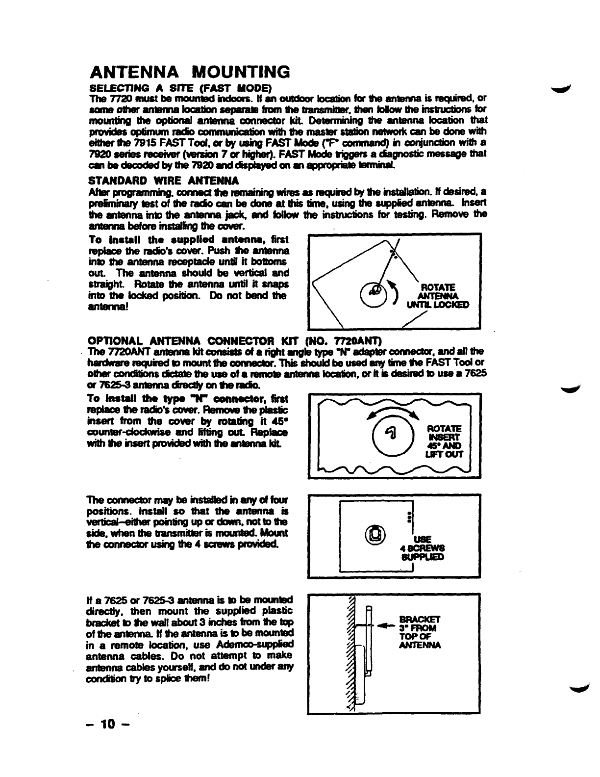
.------ .------------. -”--- 3SELECTINGASITE(FASTMADE).......... 10
GErwviL”.-.--___””___ STANDARDWIREANTENNA——......”.10
Ma--_-----..-.._.”-.”------; ANTENNACONNECTORKIT———-. 10
LOWBAITERYSHUTDOWN—- TESTINGTEEm------------------------ 11
LEDNDcAmS._ ... ..-...___._—. WiDIOTRANSMISSKXl
TEST.................11
RAM) FAULTLEDPATTERNS.....................3 W~MW~.” ----------------------- 11
SmnNG THEJUMPER
wnoNs.....................4 STATUS=CCMWND 11
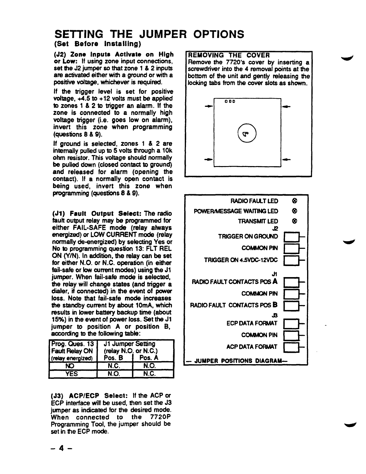
REM)VINGTHE7720’SCOVER........................4 .. ..... ..... .......
NOTESFORUL INSTALLATIONS—.......- 12
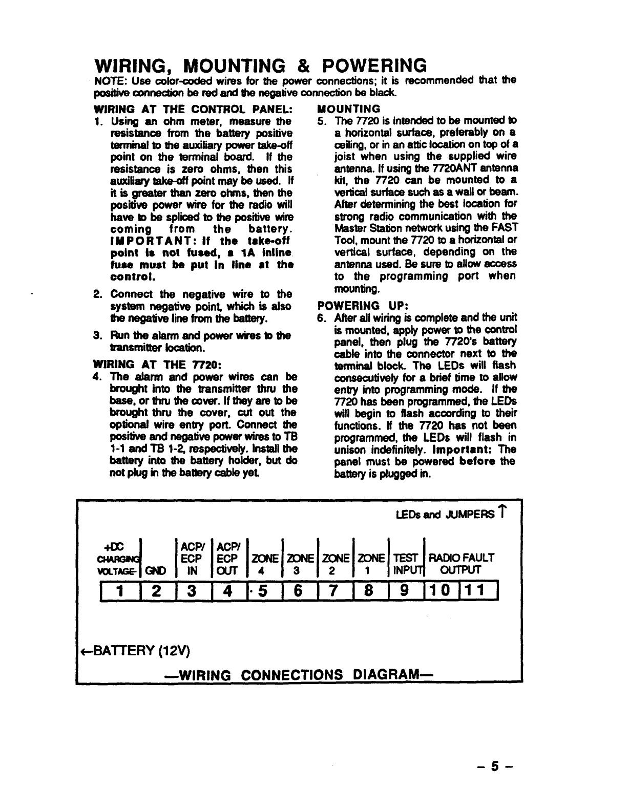
h/iRING,MCNJhmW&WRING .................5 =CFMH --------------------------- 12
P~_lNG ~ ~ “-”...”-”. ””-.-”.-... ~DIAGRAM............ ...... .... 13
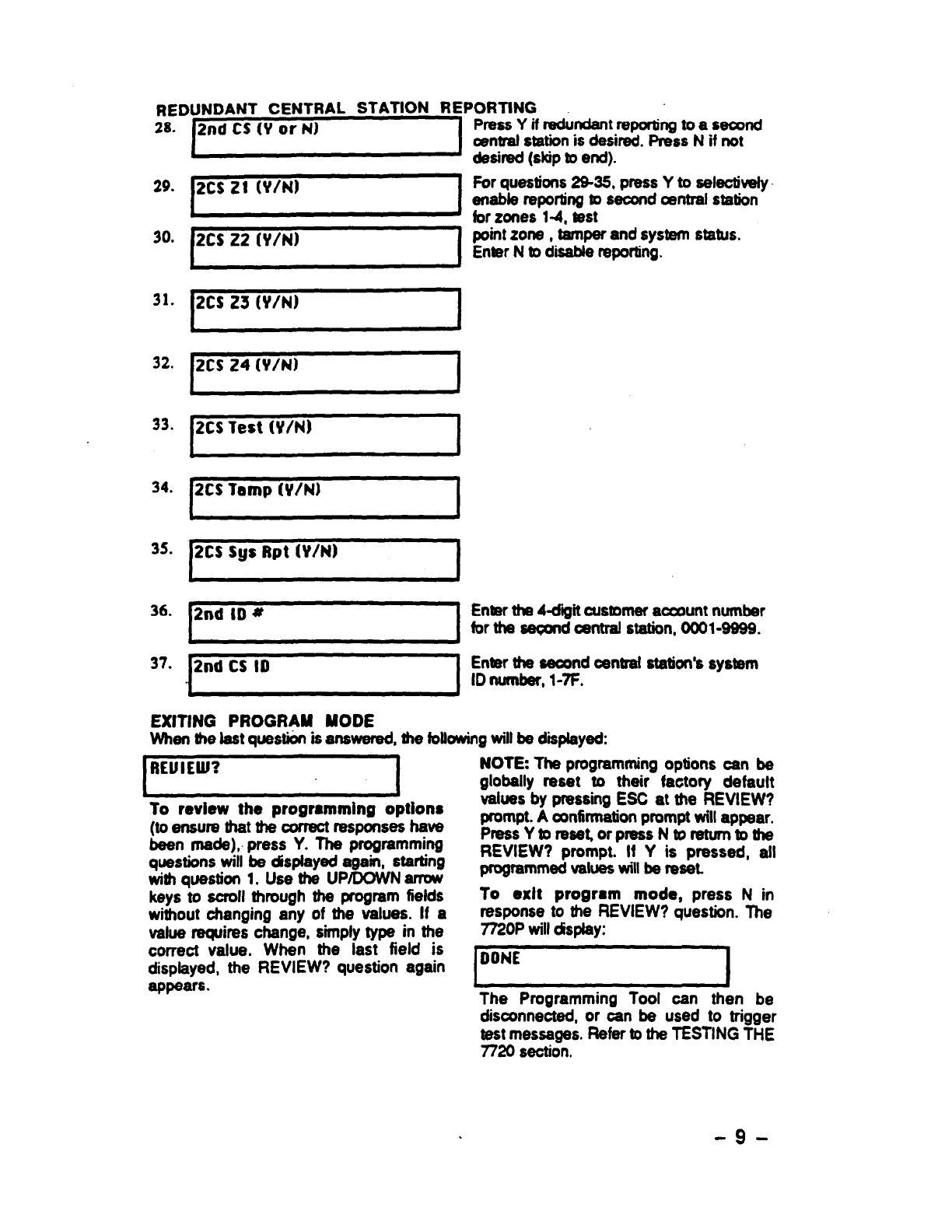
USfNGA7720PPROGFWMTOCX....... ........
PROGWt?W QUESTK3NS......................6
EXITINGPROGRAMMCK)E........ ..................9
SYSTEM FEATURES
Wireless Reporting: All alarm and Antenna Included: The 7720 comes
status messages are transmitted to the
master station network via radio signals,
which means faster and more secure
reporting.
Integrated Electronics: The entire
radio link equipment, including interface,
transmitter, power supply, battery and
antenna, is housed masingle unk requiring
only battery charging power and alarm
inputs from a standard 12 volt afarm panel.
Selection of Input Interfaces: The
7720 can monitor alarm inputs from
Ademcc ACP, Ademco ECP, discrete 4
zone contact closures or their electrical
equivalent, or from external gate and
modulation inputs.
Compatibility: The 7720 is compatible
with existing installations using ADEMCO
equipment or other control panels. The
7720 can be used in conjunction with
digital communicators on the same
system, both acting as backup to one
another (use an ADEMCO 659-EN Line
Monitor connected to azone rnputto report
afine cut and backup ad~ital dialer), whiie
connecting the radm fauft output to azone
on the dster.
Built-in LED Indicators: Three LEDs
are used to indicate message
transmissions, low battery condtions and
radio faults. Ablinking yellow LED
rndbates normaf O~RdkX1.
Built-in Tamper Protection: For
added protection, built-in cover tamper
switches will triggeran afarm whenever the
chassis cover is removed, thus protecting
against unauthorized access to the 7720.
The tamper zone number must be entered
in programming question 25 to enable
protection.
-2-
with an omni-directional wire antenna, and
also features an optional antenna kit
(7720ANT) for using a 7625 antenna.
Programmable Features: The 7720
utilizes EEROM (Electrically Erasable
ROM) technology, which allows the 7720 to
be programmedwith a7720P Programming
Tool. The programming options incfude
channel assignments for Telco fault input,
inverted trigger inputs, delayed reporting
channels (16 second delay, if selected),
open/close/restore reporting channels,
etc.
Self-Diagnosing Transmitter:
Malfunctions of the transmitter, including
antenna fault, low output power, loss of
external power, bw internal DC vottage and
internal radio-frequency circuit problems
can be reported on both the ACP/ECP
interfaces, as well as being transmitted to
the master station network, if the fault
does not prectude such transmission. For
other alarm panels, faults can trigger
contact cfosures on aForm ‘C” relay to
rndicate radio faults.
Power Supply: The 7720 is powered by
its own 12 volt battery, which can be
charged by an alarm panel’s output voltage
(14.O-14.2VDC). The charging input draws
approximately 50mA continuous and
400mA peak current during transmission.
Low Battery Monitoring: The system
will notify the central station of alow
battery condition whenever the battery
voka~ drops bdOW 11 .2V (t 5’Yo).
Low Battery Shutdown: If for any
reason the battery voltage drops Mow
9.75 volts, the radio will automatically
shutdown. Refer to the LOW BAllERY
SHUTDOWN section for more information.