manuals.online logo
Brands
  1. Home
  2. •
  3. Brands
  4. •
  5. ADEMCO
  6. •
  7. Security System
  8. •
  9. ADEMCO VISTA XM Series Product manual

ADEMCO VISTA XM Series Product manual

VISTA
XM
SERIES
TECHNICAL REFERENCE
MANUAL
www.PDF-Zoo.com
firealarmresources.com
CONGRATULATIONS
- and WELCOME to the VISTA XM FAMILY!
Thepurposeof this TECHNICAL REFERENCEMANUAL is to give you, theinstaller,a
betterunderstandingof theoperationandcapabilitiesof theVISTA XM Seriesof products.
From the most basicconfiguration to themost complex, this manual will help you fully
understand each option, step-by-step. The manual defines the system components,
provides spec.ificwiring andprogramming instructions (complemented with numerous
diagrams)anddescribesthe system’soperation.In addition, a comprehensiveglossaryis
includedto helpavoidconfusionwith thesystem’sstateof theart terminology.
As always,ADEMCO is therefor YOU! Our SALES andTECHNICAL SUPPORTstaff
areeagerto assistyou in anyway they can,sodon’thesitateto call, for anyreason!
East Coast Technical Support: l-800-645-7492 (8 a.m.-6 p.m. EXT.)
West Coast Technical Support: 1-800-458-9469 (8 a.m.-5 p.m. P.S.T.)
Again,CONGRATULATIONS, andWELCOME ABOARD!
1 NOTE: THIS ISSUE HAS BEEN SUBSTANTIALLY REVISED. 1
ADEbfCO’s VISTA XM SERIES TECHNICAL REFERENCE MANUAL
www.PDF-Zoo.com
firealarmresources.com
3
TABLE OF CONTENTS
I. GENERAL INFORMATION ....................................................................................7
II. HARDWARE OVERVIEW
9
.......................................................................................
A VlSTA XM CONTROL PANELS ...................................................................................
B. REMOTE CONSOLES 8 KEYSWlTCH.. ..................................................................... 1:
C. DIALERS ................................................................................................................. 11
D. 2.WIRE SMOKE DETECTORS.. ................................................................................ 11
E. P-WIRE POLLING LOOP DEVICES ............................................................................ 12
F. WIRELESS DEVlCES.. ............................................................................................ .15
G. SOUNDERS ............................................................................................................. 16
H. MISCELLANEOUS ACCESSORIES.. ........................................................................ 17
Ill. ZONE TYPE DEFINITIONS ................................................................................19
IV. SYSTEM CONFIGURATION (ZONES)
......................................................... .21
A. BASIC 9 HARD-WIRED ZONES ................................................................................
B. ZONE EXPANSION MODULE .................................................................................. I:
C. P-WIRE POLLING LOOP EXPANSION ...................................................................... 25
D. WIRELESS ZONE EXPANSION ............................................................................... 30
E. ZONE EXPANSION COMBlNATlONS .............. ......................................................... .36
V. SYSTEM CONFIGURATION (PERIPHERALS) ........................................
97
A. REMOTE CONSOLES .............................................................................................. 37
B. EXTERNAL SOUNDERS .......................................................................................... 36
C. SMOKE DETECTOR CONFlGURATlONS .................................................................. 41
D. PASSIVE INFRARED MOTlON DETECTORS (PIRs) 43
...................................................
E. PHONE LINE INTERFACE.. ..................................................................................... .45
k AUXILIARY VOLTAGE TRIGGERS ............................................................................. 47
REMOTE KEYSWITCH OPERATlON 8 WIRING 48
..........................................................
VI. MOUNTING PROCEDURES ..............................................................................
49
A. MOUNTING THE 4140XM CABINET 49
...........................................................................
B. MOUNTING THE 413OXM/513OXM CONTROLS.. ...................................................... .49
C. ADJUSTING THE ALPHA CONSOLE LCD VIEW ANGLE ........................................... 54
VII. POWERING THE SYSTEM ...............................................................................55
VIII. SYSTEM OPERATION .........................................................................................
57
A. SECURI-W ACCESS CODES 57
....................................................................................
B. KEYPAD FUNCTIONS ........................................................................................... ..4 9
C. TROUBLE CONDITIONS .......................................................................................... .61
D. RECALLING ALARM/TROUBLE MESSAGES.. .......................................................... 62
IX. SYSTEM COMMUNICATIONS .........................................................................
63
A. DIGKAL COMMUNICATOR OPERATION .................................................................. .63
8. COMMUNICATION FORMATS .................................................................................. .64
ADEMCO’s VISTA Xbf SERIES TECHNXCAL REFERENCE MANUAL
www.PDF-Zoo.com
firealarmresources.com
4
TABLE OF CONTENTS (cont.)
X. PROGRAMMING THE SYSTEM ........................................................-.........-....71
A.
;:
ii:
E
H:
I;
K-.
L.
ri
0.
GENERAL INFORMAnON ........................................................................................ 71
SECURITY ACCESS CODES.. 75..................................................................................
ZONE DEFINlTlONS ................................................................................................. 76
RF OPTIONS ............................................................................................................ 78
SYSTEM OPTIONS .................................................................................................. . 0
SOUNDER OPTIONS .............................................................................................. .83
TELEPHONE OPTIONS 04...........................................................................................
REPORTING OPTIONS ............................................................................................ -87
SELECT REPORTING FORMAT.. ............................................................................. .88
3+1/4+1 STANDARD OR EXPANDED REPORT SELECTION ..................................... 89
ZONE CHANNEL ASSIGNMENTS ............................................................................. 91
REPORT CODES .....................................................................................................
4+2 EXPANDED FORMAT EVENT/ID CODES ........................................................... i:
DOWNLOADING OPTIONS ....................................................................................... 94
PROGRAMMING ZONE DESCRIPTIONS .................................................................. .95
Xl. DOWNLOADING.. ...................................................................................................99
XII. TESTING THE SYSTEM.. .................................................................................103
XIII. SPECIAL UL REQUIREMENTS.. ...................................................................105
XIV. TROUBLESHOOTING ........................................................................................I
13
A. CONSOLES.. ......................................................................................................... 113
B. HARD-WIRED ZONES, 1-9.. .................................................................................... 114
C. RPMs.. .................................................................................................................. .115
D. WIRELESS ........................................................................................................... .116
E. COMMUNICATIONS ............................................................................................... 118
XV. GLOSSARY OF TERMS.. ..................................................................................
I
19
XVI. SPECIFICATIONS ...............................................................................................
123
XVII. SUMMARY- OF CONNECTIONS & PROGRAMMING DEFAULTS.129
A. SUMMARY OF CONNECTIONS.. ............................................................................ .129
8. PROGRAMMING DEFAULT VALUES ...................................................................... 132
ADEMCO’s VISTA XM SERIES TECHNICAL REFERENCE MANUAL
www.PDF-Zoo.com
firealarmresources.com
5
LIST OF DIAGRAMS
1.
2A.
28.
3.
4.
5.
6.
7.
8.
9.
10.
11.
12.
13.
14.
15.
16.
17.
18.
19.
20.
21.
22.
23.
24.
25.
26.
27.
28.
29.
30.
31.
32.
33.
34.
35.
36.
37.
38.
39.
40.
41.
42.
43.
44.
45.
P-WIRE SMOKE DETECTOR HOOK-UP .............................................................................................. 21
ZONES 2-8 EOLR SUPERVISED CONFIGURATION ............................................................................ 22
ZONES 2-8 CLOSED-CIRCUlT UNSUPERVISED CONFIGURATIONS.. ................................................ .22
ZONE 9 FAST RESPONSE - UNSUPERVISED ONLY.. ....................................................................... .23
4152LMB INSTALLATION 8 WIRING .................................................................................................. -24
ZONE EXPANSION DIAGRAMS ......................................................................................................... -25
4197 POWER CONNECTIONS ........................................................................................................... 26
419OWl-l LEFT/RIGHT ZONES ........................................................................................................... -27
4208 SUMMARY OF CONNECTIONS.. .................................................. ............................................. .28
4280 AND 4280-8 RF RECEIVERS .................................................................................................... .31
SINGLE WIRELESS RECEIVER CONFIGURATION .............................................................................. 33
TWO WIRELESS RECEIVERS REDUNDANT CONFIGURATION ........................................................... 33
TWO WIRELESS RECEIVERS TO INCREASE COVERAGE. ................................................................ 34
ZONE EXPANSION COMBINATION CONFIGURATIONS ...................................................................... .36
REMOTE CONSOLE HOOK-UP.. ....................................................................................................... .37
SOUNDER OPTIONS FOR 4140XM CONTROL .................................................................................. .38
SOUNDER OPTIONS FOR 5130XM OR 4130XM CONTROLS .............................................................. 39
4148 RELAY MODULE.. .................................................................................................................... .39
TWO 702 SIRENS IN SERIES .............................................................................................................. 40
TWO 719 SIRENS IN PARALLEL.. ...................................................................................................... 40
ZONE 1 EOLR SUPERVISED FOR BWIRE SMOKE DETECTORS .................................................... ...4 1
ZONES 2-8 EOLR SUPERVISED FOR 4-WIRE SMOKE DETECTORS ................................................. .41
P-WIRE POLLING LOOP SMOKE DETECTORS.. ................................................................................ .42
RF SMOKE DETECTORS.. ................................................................................................................ .42
4196 POLLING LOOP PIR ................................................................................................................. .43
4275 POLLING LOOP PIR ............................................................................................................... ...4 4
5775 WIRELESS PIR.. ....................................................................................................................... .44
INSTALLING THE 4171XT-XM DIALER WlTH THE 4130XM15130XM CONTROLS ................................. .45
PHONE LINEAND GROUND START CONNECTlONS ......................................................................... .46
4171XT-XMI4171XM AUXILIARY VOLTAGE TRIGGERS ...................................................................... .47
KEYSWlTCH WIRING ......................................................................................................................... .48
SURFACE MOUNT INSTALLATIONS .................................................................................................. 50
FLUSH MOUNTING - BASIC ............................................................................................................... 51
INSERTING THE NAMEPLATE .......................................................................................................... ..5 2
FLUSH MOUNTING WlTH TRIM RING .................................................................................................. .53
PRE-WIRUNEW CONSTRUCTION.. .................................................................................................... 54
POWER FLOW CHART ....................................................................................................................... 55
POWER PACK AND BAlTERY CONNECTlONS .................................................................................. 58
4140ATX UL GRADE A INSTALLATION.. ............................................................................................ I 05
UL GRADE AA 4140ATX CONNECTED TO 698UL DERIVED CHANNELSTU.. .................................... .I06
UL GRADE AA TAMPER CIRCUIT WITH A 698UL STU.. ....................................................................... I 07
UL GRADE A4140ATX CONNECTED TO A 7621AD LONG RANGE RADIO TRANSMllTER ................. 108
UL GRADE AA INSTALLATION USING A 445 HIGH LINE SECURITY TRANSMITTER.. .......................... .109
UL GRADE A CENTRAL STATION INSTALLATION USING A 346 POLICE CONNECTlON ,110
.....................
414OXM SUMMARY OF CONNECTIONS DIAGRAM ............................................................................. 130
4130XM15130XM SUMMARY OF CONNECTIONS ............................................................................... 131
ADt?btCO’r VISTA XM SERIES TECHNICAL REFERENCE btANVAL
www.PDF-Zoo.com
firealarmresources.com
6
LIST OF TABLES
1. DIP SWlTCH TABLE, POLLING LOOP DEVICES.. ................................................................................ -29
2. DIP SWITCH TABLE, WIRELESS DEVICES ........................................................................................... 35
3. BATTERY STANDBY TABLE ................................................................................................................ 55
4. CONTACT ID REPORTlNG CODE DEFlNlTlONS ................................................................................... .66
5. LOW SPEED DIGITAL COMMUNICATOR MESSAGE FORMATS.. ......................................................... .70
6. SUMMARY OF PROGRAMMING COMMANDS ...................................................................................... .73
7. INDEX TO PROGRAMMING FIELDS ..................................................................................................... .74
8. VOCABULARY OF WORDS STORED IN MEMORY ................................................................................ 98
9. AUXILIARY CURRENT DRAW WORKSHEET.. ...................................................................................... .129
10. POLLING LOOP CURRENT DRAW WORKSHEET.. ............................................................................. .129
11. STANDARD PRE-PROGRAMMED DEFAULTS.. ........................... ....................................................... .132
12. STANDARD LOW SPEED 3+1/4+1 PRE-PROGRAMMING.. ................................................................. .143
13. EXPANDED LOW SPEED 3+1&l PRE-PROGRAMMING.. ................................................................. .145
14. ADEMCO HIGH SPEED PRE-PROGRAMMING .................................................................................... .147
15. 4+2 EXPANDED FORMAT PRE-PROGRAMMING ................................................................................ .149
STEP 1
STEP 2
STEP 3
STEP 4
STEP 6
STEP 6
STEP 7
SEVEN STEPS TO EASY INSTALLATION
The following steps are required to properly install a VISTA XM system:
Become familiar with the system by reading the GENERAL INFORMATION section.
Determine the hardware required for the installation by reviewing section II: 7-Y
HARDWARE OVERVIEW.
Determine the system’s zone configuration and wiring requirements by reviewing
section Ill: ZONE TYPE DEFINITIONS, section IV: SYSTEM CONFIGURATION
(ZONES) and section V: SYSTEM CONFIGURATION (PERIPHERALS). If the
installation is UL rated, check the special UL requirements in section XIII.
Once the wiring is completed, mount the Control and make power connections
following the instructions provided in section VI: MOUNTING PROCEDURES and
section VII:’ POWERING THE SYSTEM.
Learn how the system operates, including security codes and keypad functions by
reading section VIII: SYSTEM OPERATION.
lf the system is to be supervised by a central monitoring station, read section IX:
SYSTEM COMMUNlCATlON for descriptions of reporting formats and a list of
communication programming default tables.
Program the system via the keypad or by downloading from a remote location,
following the instructions in section X: PROGRAMMING THE SYSTEM and section Xl:
DOWNLOADING (if applicable).
Test the system and teach the user how to perform all commands, following the
procedures in section XII: TESTING THE SYSTEM.
If problems occur, refer to section XIV: TROUBLESHOOTING.
ADVlSORtES Throughout this manual, information that requires special attention is highlighted in
the ADVISORIES paragraphs. This information includes system limitations, caveats
and other information vital to the proper operation of the system. Be sure to read
these paragraphs carefully.
MODEL NUMBERS Unless otherwise noted, product model numbers listed in this manual refer to
Ademco products.
ADEMCO’s VISTA XM SERIES TECHNICAL REFERENCE Mi NVAL
www.PDF-Zoo.com
firealarmresources.com
SECTIONI
7
SECTION I
GENERAL INFORMATION
THE VISTA CONTROLS The VISTA XM Controls are microprocessor based programmable systems
which provide up to 9 wired zones of protection, expandable to 64 zones
(wired and/or wireless) when connected to a 2-wire polling bop. The VISTA
XM Series includes the 4130XM, 5130XM. and 4140XM Controls and the
4137 8 5137 Remote Consoles, which are look-alikes to the 4130XM 8
5130XM respectively. Connections to the Control are made via a plug-in
connector, which can be removed without disturbing any of the field wiring.
The phone lines are connected to a separate block located on the
communicator board (4171 XT-XM or 4171XM; ordered separately wtth the
413OXMI 5130XM; 4171 XT-XM included with the 4140XM).
l
4140XM
The 4140XM is housed in a metal cabinet, measuring 12’ x 12” x 3’, and
requires the use of either the 4137 fixed message or 5137 alpha-numeric
(allowing use of the 4140XM’s built-in vocabulary) remote consoles. and can
also be used with the 4146 keystation. A SPDT relay, rated @ 2.8 amps, is
built-in for use with a No. 702, or No. 719 (or equivalent) exterior sounder. For
UL mercantile installations, the 414OAlX can be used. The 4140ATX is the
same as the 4140XM, but features a larger, heavier gauge cabinet and a
cabinet tamper switch.
l
4130XM
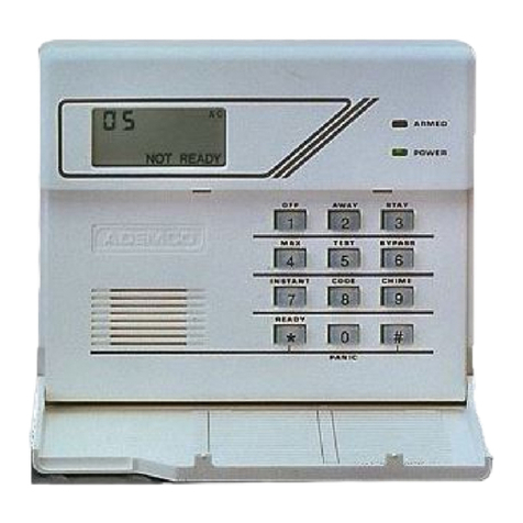
The 4130XM is a self-contained Control with an LCD using 2 numeric digits
for zone identification, and a set of pre-designated English language
prompts, for system status (ex: ‘READY’, “NOT READY). A built-in 85dB UL
listed sounder is also included. The Control can be surface or flush mounted.
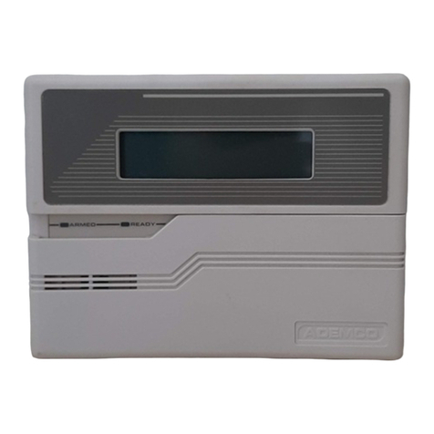
The 5130XM is also a selt-contained Control, but with a O-line, 32character
(16 characters per tine), back-lit, programmable alpha-numeric LCD. Unlike
the 4130XM, the 5130XM (and 4140XM. when used with the 5137 console)
contains a bultt-in 220 word vocabulary from which to choose words for
describing each zone in friendly English language. In addition. up to 5
custom word entries to suit the individual needs of each installation can also
be programmed. Like the 4130XM, the 5130XM contains a built-in 85dB UL
listed sounder and can be surface or flush mounted.
.
5130XM
a-
EASY PROGRAMMING
The Control can be programmed either on the job site directly from the
keypad, or remotely by using the ADEMCO 4130PC DOWNLOADING
SOFTWARE, an IBM (or compatible) computer, and a HAYES 1200
Smartmodem. (See the PROGRAMMING section for a complete explanation).
All programmed options are stored in non-volatile EEROM memory. This
means that old fashioned PROM chips are no longer needed, and the
program can be changed over and over again, as the needs of a particular
system grow. It also means that the program cannot be bst or changed In any
way if power to the Control is bst. Even if completely powered down for long
periods of time, the program will remain intact.
For installer convenience, the Control is pre-programmed with a set of
‘standam values that is designed to meet the needs of many installations.
These values, however, can be changed to suit the needs of any particular
installation. Specific programming instructions are provided in the
PROGRAMMING section of this manual.
ADEMCO'x VISTA XM SERIES TECHNIcAt REFERENCE MANUAL
www.PDF-Zoo.com
firealarmresources.com
8 GENERAL INFORMATION
.n
MEMORY-OF-ALARM
The VISTA Controls provide a memory-of-alarm feature, which, upon
disarming the system, automatically displays all zones that were in an alarm
condition while the system was armed. To cancel this display, the user simply
enters the security code and presses the OFF key. In addition, a 10 day
alarWtrouble history is maintained by the system, which helps the installer or
central station to identify problem sensors. To activate this feature, enter the
security code + the [O] key. To clear the display, enter the security code and
press the OFF key. Note that once the 10 day alanwtrouble history display
has been cleared, it is also cleared from the system’s memory.
BUILT-IN
For end-user wnvenience. the 5130XM and 4140XM (with 5137) contain a
USER’S MANUAL/
“built-in Users Manual. By depressing and holding any of the function keys
DESCRIPTOR REVIEW
on the console for 5 seconds, a brief explanation of that particular function
scrolls across the ALPHA-NUMERIC display. For example, if the user forgets
how to bypass a zone, he or she simply depresses the key marked
“BYPASS and holds it for 5 seconds. The information will then scroll across
the display, explaining how to bypass a zone.
In addition, all programmed zone descriptors can be displayed (one at a time)
by pressing and holding the READY key until the key’s instructions appear (5
seconds), then releasing the key. This serves as a check for installers to be
sure all descriptors are entered properly. This feature is also helpful to the
user when there is a need to know the zone number of a particular sensor (as
when bypassing zones).
COMMUNICATIONS
The system can be monitored by a central station, via the switched telephone
network. Upon alarms, programmed communicator reports will be transmitted
up to the programmed maximum (swinger suppression) in one armed interval.
Restoral reports will be sent when the zone is restored for a time greater than
#s physical response time (less than 1 second). In addiiion, the system also
sends system status reports(AC loss, system trouble, etc.). The system also
provides voltage triggers for other communication devices, such as
Ademco’s Long Range Radio system.
:--. .
..--..
ADEbiCO’s VISTA XM SERIES TECHNICAL REFERENCE MANUAL
www.PDF-Zoo.com
firealarmresources.com
SECl7ON II 9
SECTION II
HARDWARE OVERVIEW
- A. VISTA XM SERIES CONTROL PANELS -
COMMON FEATURES
l
4140XM
L Q
W’L XM
l
5130XM ’
l
Basic 9 wired zones, expandable to 84 zones (wired, and/of wireless).
l
22 user codes.
l
Downloadable (office or site initiated).
l
Independent auxiliary voitage trigger outputs for FIRE, PANIC, BURG,
and OPEN/CLOSE.
l
ADEMCO High Speed, 4+2, traditional low speed, ADEMCO’s Express
and the new Contact ID communication formats available.
VISTA XM CONTROL (Cabinet Mounted)
l
Housed in a metal cabinet measuring 12” x 12” x 3’.
9 700 mA continuous auxiliary power.
l
Built-in SPDT alarm relay rated for 2.8 amps @28 v&s.
l
Alpha-Numeric zone descriptors (with 5137 remote console) with a buift-
in 220 word dictionary, plus an additional 5 custom word entries and an
installer’s message can be programmed (ex: ABC Alarms Call 1-800-l 23-
4567).
. Removeable terminal strip for easy installation and service.
l
Up to a 6AH battery can be used for maximum standby time (gel cell
only!).
l
Built-in ‘User’s Manual” and ‘Descriptor Review Mode’ (with 5137 remote
console).
VISTA XM FIXED-WORD CONSOLE/CONTROL
l
Se!-contained, compact design.
l
Surface or Flush mounted (hardware included).
. Liquid Crystal Dispiay (LCD) with P-digit numeric zone identification and
pre-designated English language prompts for system status (ex:
-READY-,
l
NOT READY=).
l
Built-in UL sounder (85 dB Ql 0 leet).
l
Removeable wiring harness for easy installation and service.
VISTA XM ALPHA CONSOLE/CONTROL
l
Self-contained, compact design.
l
Surface or Flush mounted (hardware included).
l
a-line. 32-character. Alpha-Numeric Liquid Crystal Display (LCD),
programmable for English language descriptors of each zone (ex:
“JOHNNY’S ROOM”).
l
Builtin ‘User’s ManuaP and ‘Descriptor Review Mode’.
l
Built-in UL sounder (85 dB @ 10 feet).
. Removeable wiring harness for easy installation and service.
ADEMCO’s VISTA XM SERIES TECHNICAL REFERENCE MANUAL
www.PDF-Zoo.com
firealarmresources.com
10 HARDWARE OVERVIEW
- B. REMOTE CONSOLES & KEYSWITCH -
l
4137 49WIRE, 4130XM LOOK-ALIKE CONSOLE
l
Equrpped with a liquid crystal display (LCD) using P-digit numerics for
zone identification, and a set of predesignated English language
prompts, such as ‘READY’. ‘NOT READY. etc. for system status.
l
A built-in alarm sounder is also included, which eliminates the need for a
separate indoor sounder.
l
The 4137 can be used with the 4130XM. 5130XM, and 4140XM
Controls.
l
4146
4.WIRE, 5130XM LOOK-ALIKE CONSOLE
l
Equipped with a programmable O-line, 32-character (16 characters per
line), back-fit, ALPHA-NUMERIC LCD for complete zone identification in
English tanguage (if descriptors are programmed).
. An alarm sounder is built in, eliminating the need for a separate indoor
sounder.
. The 5137 can be used with the 5130XM and 4140XM Controls.
,-,
REMOTE KEYSWITCH KIT
l
The remote plate contains 2 LED’s for system status, and houses a
spring-loaded keyswitch for arming and disarming the system.
l
An optional tamper switch (No. 112) can be added, if desired.
l
All of the VISTA XM Controls can accommodate one No. 4146 remote
plate. (More than one can be used if 688-12 switching modules are used
to boost the LED drive outputs for ARMED and READY status.)
.n.
ADEMCO’s VISTA XM SERIES TECHNICAL REFERENCE MANUAL
www.PDF-Zoo.com
firealarmresources.com
HARDWARE
OVERVIEW 11
- C. DIALERS -
l
4171XM DIALER (for 9 zone configuration)
l
For use with either the 4130XM or 5130XM in the basic 9 zone
configuration.
l
Auxiliary voftage triggers for FIRE, PANIC, BURG, and OPEN/CLOSE.
. ‘Site-initiiefl Downbading.
l
ADEMCO High Speed, ADEMCO Express, Contact ID, 4+2, and
traditional low speed formats.
. Ground Start compatible.
l
417IXT-XM DIALER (for expanded zone configuration)
l
For use with either the 4130XM or 5130XM (factory installed with
4140XM).
,
l
Expansion, up to 54 zones (when interfaced wfth the 4152LMB).
l
Auxiliary voltage triggers for FIRE, PANIC, BURG, and OPEN/CLOSE.
l
Full Download capabilities (site or office initiated).
l
ADEMCO High Speed, ADEMCO Express, Contact ID, 4+2, and
traditional low speed. formats.
l
Ground Start compatible.
-.
’ 1400
l
2-wire,
IONlZATtON.
l
2400
l
2-wire, PHOTOELECTRIC
l
2400TH
l
P-wire, PHOTOELECTRIC with 135OF (57” C) heat detector.
- D. 2-WIRE SMOKE DETECTORS -
l
Up to three P-wire BRK smoke detectors can be used. Compatible detectors
include:
ADEMCO’s VISTA XM SERIES TECHNICAL REFERENCE MANUAL
www.PDF-Zoo.com
firealarmresources.com
12
XARDWARE OVERVIEW
- E.
l
4152LMB
4280
4280-8
4208
20WIRE POLLING LOOP DEVICES -
POLLING LOOP MODULE
l
When interfaced with the 4171XT-XM dialer board, polling loop and/or
wifeless zone expansion to 64 zones can be accomplished using RPMs
(Remote Point Modules) and/or the 4280 RF receiver module with
ALERT Ill transmitters.
RF RECEIVER MODULE (63 zones)
200 foot range.
Connected to the 4152LMB via a O-wire polling loop, the 4280 can be
used with up to 63 wireless transmitters (ALERT Ill ). plus a wireless
keypad.
House ID ‘SNIFFER’ Mode to ‘sniff out” all other house ID’s from
neighboring systems in the local area.
Transmitter ‘SNIFFER‘ Mode to ‘sniff out’ any transmitters which are
using your House ID.
Up to two 4280s can be used in a system for redundancy, or to increase
the area of coverage.
Powered directly from the polling loop, or separately from auxiliary power.
NOTE: If two 4280s are used. the second 4280 must be powered from
auxiliary power
,Y---.
RF RECEIVER MODULE (8 zones)
l
200 foot range.
l
Connected to the 4152LMB via a P-wire polling loop, the 4280% can he
used with up to 8 wireless transmitters (ALERT Ill type).
. House ID ‘SNIFFER” Mode to -sniff out’ all other house ID’s in the local
area.
l
Transmitter ‘SNIFFER’ Mode to ‘sniff out’ any transmitters which are
using your House ID.
l
Up to two 42808s can be used for redundancy, or to increase the area of
coverage.
. Powered directly from the polling loop, or separately from auxiliary power.
NOTE: If two 4280%~ are used, the second 4280-8 must be powered
from auxiliary power
EIGHT ZONE POLLING LOOP EXPANSION MODULE
l
Connected to the 4152LMB via a P-wire polling bop and is used with up
to 8 hard-wired devices.
l
Set DIP switches to identify 8 zones.
. The first two zones can be either normal or fast response (DIP switch
selectable).
. All zones are EOLR supervised (first six zones = 4.7K, last two zones =
30K).
l
NOTE: Does not support O-wire smoke detectors. ,-,
ADEMCO’s VISTA XM SERIES TECHNICAL REFERENCE MANUAL
www.PDF-Zoo.com
firealarmresources.com
HARDWARE OVERVIEW
13
l
4190WH
l
4139WH (White) or
4139GY (Gray) or
4139BR (Brown)
l
4191WH
TWO-ZONE REMOTE POINT MODULE
l
DIP switch programmable. The left zone can be EOLR supervised, if
necessary, and can accept either open or closed circuit ‘sensors. The
rtght zone is unsupervised and can accept closed circuil sensors only.
l
Connected to 4152LMB via a O-wire polling bop.
SURFACE MOUNTED REED CONTACT (Compact)
l
Compact surface mounted magnetic reed contact with built-in RPM. The
4201 programmer must be used to program this contact.
l
Connected to 4152LMB via a P-wire polling loop.
SURFACE MOUNTED REED CONTACT (Wide Gap)
l
Wide Gap Surface mounted reed contact with built-in RPM; DIP switch
programmable.
l
Connected to 4152LMB via a a-wire polling hop.
RECESSED REED CONTACT
. Recessed (l/2- dia.) magnetic reed contact with built-in RPM. The 4201
programmer must be used to program this contact.
l
Connected to 4152LMB via a O-wire polling loop.
RPM PROGRAMMER
l
Portable Programmer for the 4139 and 4191 contacts.
RECESSED REED CONTACT STEEL DOOR ADAPTER
l
Plastic adapter plug for the 4191WH. Should be used when instalting the
amtact into a metal frame.
l
4192SD PHOTOELECTRIC SMOKE DETECTOR
. One piece photoelectric smoke detector with built-in RPM; DIP switch
programmable.
. Connected to 4152LMB via a P-wire polling bop.
ADEMCO’s VISTA XM SERIES TECHNICAL REFERENCE MANUAL
www.PDF-Zoo.com
firealarmresources.com
.
14
HARDWARE OVERVIEW
. 4192SDT PHOTOELECTRIC SMOKE DETECTOR
W/HEAT DETECTOR
l
One piece photoelectric smoke detector with 135OF (57°C) Heat
Detector. The built-in RPM is DIP switch programmable.
l
Connected to 4152LMB via a P-wire polling loop.
l
4192CP
l 4196
. 4275
IONIZATION SMOKE DETECTOR
l
One piece products of combustion ionization detector with built-in RPM;
DIP switch programmable.
l
Connected to 4152LMB via a O-wire polling bop.
QUAD ELEMENT PASSIVE INFRARED DETECTOR
.
PIR with built-in RPM; DIP switch programmable: included are mirrors for
both Wide Angle and Long Range applications: Has a separate right zone
which can accept closed circuit sensors only (no EOLR supervision).
l
Connected to 4152LMB via a 2-wire polling loop.
DUAL ELEMENT PASSIVE INFRARED DETECTOR
l
PIR with built-in RPM: DIP switch programmable: included are mirrors for
both Wide Angle and Curtain/Long Range applications.
l
Connected to 4152LMB via a a-wire polling loop.
l
Built-in pulse count capability (selectable).
l
Can use the 1875PA Pet Alley mirror.
POLLING LOOP EXTENDER MODULE
.
If the 2-wire polling bop must be greater than the recommended length
(4000’ maximum), the 4197 ts required. By installing the 4197 at the end
of the first loop, you can now continue your polling loop. If more than 84
mA needs to be drawn from the polling loop to power RPM% use of the
4197 provides another bop with 84mA available.
l
Connected to the O-wire polling bop and is powered from auxiliary power
or by a separate 729 power supply with battery backup.
ADEMCO’s VISTA XM SERIES TECHNlCAL REFERENCE MANUAL
www.PDF-Zoo.com
firealarmresources.com
HARDWARE OVERVIEW 15
- F. WIRELESS DEVICES -
TRANSMITTER
BATTERIES
.
.
5701
5706
H
El
I
0 1
l
5711WM
l
5715WH (white)
or 5715BR (brown)
.
5727
All transmitters use 9 volt batteries. Either Alkaline type or Kodak lithium
batteries may.be used. Lithium batteries should last 4-7 years under normal
use and have a shell life of 7 years. Transmitters will transmit a ‘Low Battev
signal when battery has 30 days of life remaining.
PANIC TRANSMITTER
l
Programmable for either silent or audible 24 hour atann (can be DIP switch
programmed for zones 62 or 63).
PHOTOELECTRIC SMOKE DETECTOR
l
One piece photoelectric smoke detector with built-in transmitter (DIP
switch programmable for zones 48 through 55).
l
Built-in 85 dB piezoelectric alarm sounder
l
Built-in audible low battery warning.
SLIMLINE DOOR/WINDOW TRANSMUTER
l
Can be used with any closed circuit sensor. NOTE: Can be used on any
zone. 1 through 63 but, if programmed for 3247, there will be a 3 minute
lockout between transmissions.
DOOR/WINDOW TRANSMlTTER W/REED SWITCH
. Sfimline doorlwindow transmitter with a built-in reed switch (magnet
included). Can be used with any closed circuit sensor. NOTE: Can be
used on any zone, 1 through 63, but, if programmed from 3247, there
will be a 3 minute lock-out between transmissions.
UNIVERSAL TRANSMITTER
.
DIP switch selectable for fast response, open or closed circuit sensor
usage, and has a tamper protected cover. Use in applications where
open circuit Heat Detectors are needed or where fast response devices
are needed. NOTE: Can be used on any zone, 1 through 63, but, if
programmed from 3247, there will be a 3 minute lock-out between
transmissions.
WIRELESS KEYPAD
l
Wireless keypad that can be used to turn the burglary protection on and
off with built-in panic function, [‘I + [#I, for either a silent or audible 24
hour alarm. There is an LED indication to verify transmission bcated in the
1’1READY key. (Each time a key is depressed the LED flashes). The
keypad is identified as zone 00 when it transmits low battery messages.
The Panic is identified as 99’.
WIRELESS PASSIVE INFRARED DETECTOR
l
Wireless Dual Element Passive Infrared (PIR). DIP switch programmable
for zones 32 through 47. NOTE: There is a 3 minute lock-out between
transmissions to preserve battery life.
l
Built-in pulse count capability (selectable).
ADEMCO’s VISTA XM SERIES TECHNICAL REFERENCE MANUAL
www.PDF-Zoo.com
firealarmresources.com
16
HARDWARE OVERVIEW
- G. SOUNDERS -
l
702 OUTDOOR SIREN
l
Self-contained siren (driver built-in) and weatherproof for outdoor use.
Can be wired for either a steady or yelp sound, and is rated at 120 dB @
10 feet. This siren can also be tamper protected, or can be mounted in a
metal cabinet (716). which can be tamper protected. Must be used with
the 4148 Relay Module when using the 4130XM or 5130XM Control.
OUTDOOR SIREN (Compact)
l
Compact, self-contained siren (driver built-in), and weatherproof for
outdoor use. Can be wired for either a steady or yelp sound, and is rated
at 90 dB @ 10 feet. A 708BE cabinet is available, which can be tamper
protected it necessary. Must be used with the 4148 Relay Module when
using the 4130XM or 5130XM Control.
HIGH INTENSITY SOUNDER
l
.Compact high intensity sounder rated at 123 dB @ 10 feet. This sounder
emits an ‘ear-piercing”, .high frequency .sound; can be mounted indoors
(bracket included)., or outdoors (can be mounted in 708BE cabinet)
702 SIREN JUNCTION BOX KIT
l
Siren junction box Kit. Recommended for use with the self-contained
controls where a 702 siren is desired. The kit includes a 4134-12 metal
cabinet with 4148 relay mounted inside, a 702 self-contained siren, and a
12 voll4.0 AH battery.
.,-.
MOTOR BELL & BOX
9 AMSECO motorbell 8 box, 81 dB @ lo’.
l
PA400B (beige) or INDOOR PIE20 SOUNDER
PA400R (red)
l
BRK indoor piezo sounder (red or beige), 90 dB @ 10
ADEMCO’s VISTA XM SERIES TECHNICAL REFERENCE MANUAL
www.PDF-Zoo.com
firealarmresources.com
GENERAL
INFORMATION
TYPE 1
TYPE 2
TYPE 3
e
TYPE 4
TYPE 5
.’
SECTION III
ZONE TYPE DEFINITIONS
SECTION III 19
The VISTA System albws up to 64 zones of hard-wire, polling loop andlor
wireless protection. Each zone must be assigned to a zone type, which
defines the way in which the system responds to faults in that zone. In
addition, there are three keypad activated zones (PANIC keys) identified as
zones 95.96 8 99, a polling bop supervision zone (zone 97) and two RF
supenrisory zones for each 4260 installed (zones 66-92).
ENTRY/EXIT #I
Used for the primary entry/exit route (ex: front door, main entrance). The
zone becomes active when the exit delay time has elapsed. Upon entry
through this zone, the system must be disarmed before the entry delay time
has elapsed or else an alarm will occur. The console will beep multiple times
upon entry (as a retinder to disarm the system).
ENTRY/EXIT #2
Used for a secondary entry/exit route (ex: Garage door, loading dock door,
basement door), where more time might be needed to get to and from the
keypad. The function of this zone type is similar to that of entry/exit #l,
except that the delay times for this zone must be greater than that of #l .
PERIMETER BURGLARY
Used for exterior doors and/or windows which require an instant alarm when
violated.
INTERIOR BURGLARY (FOLLOWER)
Used for areas where an entry delay is required only if an entry/exit delay
zone is faulted first. Usually assigned to zones such as a foyer or lobby
(containing motion detectors) through which users must pass to reach the
keypad to disarm the system. If an entry/exit zone is not faulted first, an
instant alarm occurs upon the faulting of the follower zone. Designed to
provide instant tntrusion alarm in the event an intruder hides on the premises
prior to the system being armed or gains access to the premises through an
unprotected area. This zone will always have the same exit delay time as
programmed for entry/exit #l , and will have the same entry delay time as the
entry/exit delay zone faulted first, entry/exit #l or #2.
DAY/NIGHT BURGLARY
Used for zones which contain a foil-protected door or window (such as in a
store), or to a zone covering a ‘sensitive’ area such as a stock room, drug
supply room, etc., or other controlled access area where immediate
notification of an entry is desired. During the disarmed state (day), the system
will provide latched Console annunciation, rapid beeping, zone ID and
CHECK display, (and central station report, tf desired) of openings or troubles
(such as sensor malfunctions or foil breaks). During the armed state (night),
violations will initiate an alarm, the internal (console) and external (if used)
alarm sounders will activate, and the communicator will report alarms.
ADEMCO’s VISTA XM SERIES TECHNICAL REFERENCE MANUAL
www.PDF-Zoo.com
firealarmresources.com
20
ZONE TYPE DEFINITIONS
TYPE 6 24 HOUR SILENT ALARM
This zone type is generally assigned to a zone containing a Hold-up or Panic
button that is designed to initiate an alarm report to the Central Station, but
which produces no visual displays or alarm sounds (ex: banks, jewelry
counters). Sensors assigned to this zone, when faulted, will only initiate a
programmed-communicator report.
TYPE 7
TYPE 8
TYPE 9 SUPERVISED FIRE
TYPE 10
24 HOUR AUDIBLE
This type also assigned to a zone containing a Panic button, but which will
initiate an audible alarm in addition to an alarm report to the Central Station
(ex: bedside panic). Faulting a zone of this type will initiate a kud audible
alarm externally and at the console, an LCD display, and a programmed
communicator report.
24 HOUR AUXILIARY
This type is assigned to a zone containing a button for use in personal
emergencies or to a zone containing monitoring devices such as water
sensors, temperature sensors, etc. Designed to initiate an alarm report to the
Central Station and only provides Console alarm sounds and alarm displays.
Fautttng a zone of this type will initiate a steady alarm sound at the console, an
ALARM display, and a programmed communicator report.
.*-..
Used for zones containing smoke detectors, heat detectors, pull stations,
etc. An open in this zone will initiite a trouble signal. A short in this zone will
initiate a fire alarm (pulsed external sounder and report to central station).
NOTE: Zone 1 can support up to three O-wire smoke detectors when
configured for use with a 13,000 ohm EOLR. Wired zones 1 through 8 (and
lo-94 if used) can support 4-wire smoke detectors when configured for
EOLR’s. but a manual power reset switch must be installed in order to reset
the smoke detectors after an alarm. Zones lo-94 can also use individually
identifiable a-wire polling loop smoke detectors (Zones 48-55 can use
wireless photoelectric smoke detectors). Zone 9 cannot be used for fire at
any time. Fire zones cannot be bypassed.
INTERIOR BURGLARY (DELAYED)
This type’ is similar to type 4. except that entry delay begins whenever
sensors in this zone are viotated, regardless of whether or not an entry/exit
delay zone was fautted first. This zone has the same delay times as entry/exit
#l and does not become active until after the exit delay time has elapsed.
Afterwards. if this zone is violated. entry time starts, and the system must be
disarmed before entry time elapses or an alarm will occur.
ADEMCO’s VISTA XM SERIES TECHNICAL REFERENCE MANUAL
www.PDF-Zoo.com
firealarmresources.com
HARDWARE OVERVIEW
17
- H. MISCELLANEOUS ACCESSORIES -
NP1212 (YUASA) 12 volt, 1.2 AH gel cell battery.
484 (ADEMCO) 12 volt, 1.3 AH gel cell battery.
NP412 (YUASA) 12 volt, 4.0 AH gel cell battery.
12V4P (PANASONIC) 12 volt, 4.0 AH gel cell battery.
NP812 (YUASA) 12 volt, 6.0 AH gel cell battery.
12V65P (PANASONIC) 12 volt, 6.5 AH gel cell battery.
1350 Plug-In DC power pack for the 4130XM15130XM or for provldlng
supplemental power to 413715137 consoles.
1360 Plug-In DC power pack for the 4140XM only.
413OPC DOWNLOADING software on 5-l/4” floppy disk.
413OPC-3 DOWNLOADING software on 3-112” floppy dlsk.
HAYES1200 Modem for DOWNLOADING.
4132 Battery back box for 1.2 AH battery (for 4130XM or 6130XM).
4132LG Battery back box for 4.0 AH battery (for 413OXM or 6130XM).
4132-12 Battery Klt - Includes 4132 back box and 1.2 AH battery for
4130XM15130XM.
4132-40 Battery Kit - Includes 4132LG back box and 4.0 AH battery for
4130XM/513OXM.
4134-8 Metal Cabinet (8 Inch) w/Terminal Strlp for 4130XM15130XM
4134-l 2 Metal Cablnet (12 Inch) w/Relay Module (No. 4148) and
termlnal strlp for 4130XM15130XM.
4134-15 Metal Cablnet (12 Inch) for 4130XM/5130XM.
www.PDF-Zoo.com
firealarmresources.com
18
HARDWARE OVERVIEW
4133 ROUGH-IN RING
.
Pre-wire rough-in ring, used in new construction to designate where the
plasterboard (for later mounting of a 4130XM, 5130XM, 4137. or 5137) is
to be cut, before the walls are up.
.-..
4136
ROUGH-IN RING COVER PLATE
l
Blank metal cover plate for the No. 4133 rough-in ring. Use this plate to
cover
the
hole after the walls are up, until the Control or console is
mounted.
4141-15 (4141.30) WIRING HARNESS
.
15’ (30’) wiring harness for the self-contained VISTA XM Controls. Use
this harness to remote your field connections rather than terminating
directly behind the control panel. Use with the No. 4145 Splice Box Kii.
4143
4144
4145
4148 SIREN RELAY MODULE
417lTR
659EN TELEPHONE LINE FAULT MONITOR
675 GROUND START MODULE
EXPANSION RING
l
Expansion Ring (‘8elly Band’) for surface mounting the self-contained
VISTA XM Control with the dialer board and 4152LMB connected.
-TERMINAL STRIP
.
Plug-in terminal strip for the 4130XM or 5130XM. can be used in place of
the harness.
SPLICE BOX KIT
l
Recommended for use with the 4141-15 or 4141-30 harness. The kit
includes a No. 205 8” x 10’ x 3” metal cabinet, a No. 207 adapter plate, ,-.
and two No. 312 terminal strips.
l
SPDT relay module, rated for 2.8 amps @ 28 VDC, for use with the self-
contained VISTA XM Controls when either a No. 702 or No. 719 is
desired. This relay is also used in the 4134-12 cabinet and the 4149
Siren Junction Kit.
AUXILIARY. VOLTAGE TRIGGER WIRING HARNESS
. 5-wire harness required for connection to the 4171 XT-XM auxiliary trigger
outputs.
ADEMCO’s VISTA XM SERIES TECHNICAL REFERENCE MANUAL
www.PDF-Zoo.com
firealarmresources.com

This manual suits for next models

3

Other ADEMCO Security System manuals

ADEMCO VISTA-20P Series User manual

ADEMCO

ADEMCO VISTA-20P Series User manual

ADEMCO VISTA-120 Assembly instructions

ADEMCO

ADEMCO VISTA-120 Assembly instructions

ADEMCO StreetSmart Code Encryptor II CE2Y User manual

ADEMCO

ADEMCO StreetSmart Code Encryptor II CE2Y User manual

ADEMCO via30+ User manual

ADEMCO

ADEMCO via30+ User manual

ADEMCO Security System VISTA-15 Assembly instructions

ADEMCO

ADEMCO Security System VISTA-15 Assembly instructions

ADEMCO LYNX User manual

ADEMCO

ADEMCO LYNX User manual

ADEMCO 4110DL User manual

ADEMCO

ADEMCO 4110DL User manual

ADEMCO 4110 User manual

ADEMCO

ADEMCO 4110 User manual

ADEMCO VISTA-20P Series Assembly instructions

ADEMCO

ADEMCO VISTA-20P Series Assembly instructions

ADEMCO Ademco VISTA-40 User manual

ADEMCO

ADEMCO Ademco VISTA-40 User manual

ADEMCO Vista AT User manual

ADEMCO

ADEMCO Vista AT User manual

ADEMCO 1025 User manual

ADEMCO

ADEMCO 1025 User manual

ADEMCO N7227V5 User manual

ADEMCO

ADEMCO N7227V5 User manual

ADEMCO VIA-30PSE Operating instructions

ADEMCO

ADEMCO VIA-30PSE Operating instructions

ADEMCO via30+ User manual

ADEMCO

ADEMCO via30+ User manual

ADEMCO Vista-20 User manual

ADEMCO

ADEMCO Vista-20 User manual

ADEMCO via30+ User manual

ADEMCO

ADEMCO via30+ User manual

ADEMCO 4140XMPT2 User manual

ADEMCO

ADEMCO 4140XMPT2 User manual

ADEMCO VISTA-20PS Assembly instructions

ADEMCO

ADEMCO VISTA-20PS Assembly instructions

ADEMCO VISTA-120 User manual

ADEMCO

ADEMCO VISTA-120 User manual

ADEMCO 745x3 User manual

ADEMCO

ADEMCO 745x3 User manual

ADEMCO via30+ User manual

ADEMCO

ADEMCO via30+ User manual

ADEMCO VISTA-32FB Assembly instructions

ADEMCO

ADEMCO VISTA-32FB Assembly instructions

ADEMCO VISTA 10 User manual

ADEMCO

ADEMCO VISTA 10 User manual

Popular Security System manuals by other brands

jablotron Profi user manual

jablotron

jablotron Profi user manual

ELRO FC5003 user manual

ELRO

ELRO FC5003 user manual

Axis FA54 installation guide

Axis

Axis FA54 installation guide

Honeywell INTELLIGUARD 9000 Programmer's guide

Honeywell

Honeywell INTELLIGUARD 9000 Programmer's guide

jablotron JA-84P manual

jablotron

jablotron JA-84P manual

King Pigeon K2 user manual

King Pigeon

King Pigeon K2 user manual

Pandora 397O manual

Pandora

Pandora 397O manual

Elk ELK-319GB quick start guide

Elk

Elk ELK-319GB quick start guide

Swann DVR4-Pro-Net TBA Easy setup guide

Swann

Swann DVR4-Pro-Net TBA Easy setup guide

DESi MIDLINE user manual

DESi

DESi MIDLINE user manual

Pix Controller UndercoverEye instruction manual

Pix Controller

Pix Controller UndercoverEye instruction manual

ring Z-Wave Installation & setup

ring

ring Z-Wave Installation & setup

Eldes ESIM364 user manual

Eldes

Eldes ESIM364 user manual

Smanos X500 user manual

Smanos

Smanos X500 user manual

Murphy Flasher Alarm Light and Mini-Siren SAH Specifications

Murphy

Murphy Flasher Alarm Light and Mini-Siren SAH Specifications

Altronix TROVE T3SSK7528 installation guide

Altronix

Altronix TROVE T3SSK7528 installation guide

Automatic Systems FirstLane 960 Technical manual

Automatic Systems

Automatic Systems FirstLane 960 Technical manual

GeoVision GV Series How-to guide

GeoVision

GeoVision GV Series How-to guide

manuals.online logo
manuals.online logoBrands
  • About & Mission
  • Contact us
  • Privacy Policy
  • Terms and Conditions

Copyright 2025 Manuals.Online. All Rights Reserved.