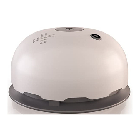
ADEMCO 4192CPM User manual

P-Mc,~
4192CPM Addressable Ionization Smoke Detector
Installation and Maintenance Instructions
Before instalkng detectors, please thoroughly read the suppoting Ademco control panel installation instructions, which
provide detailed information on detector spacing, placement, zones, and special applications. Copies of the installation
instructions are available from Ademco. NFPA 72 and NEMA guidelines should also be observed.
=
Use this smoke detector only with panels that suppofl the detector’s maintenance feature:
ADEMCO VISTA 150, First Aleti FA1600C.
GENERAL DESCRIPTION
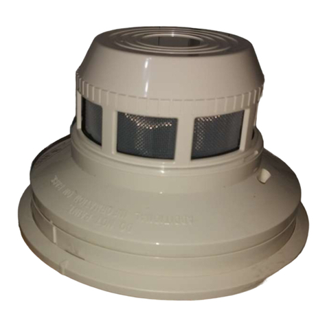
The Model 4192CPM dual-chamber ionization smoke detecto. uses astat(>-of-the-art unipolar sensing chamber. This
detector is designed to provide open area protection and to be used with compatible UL-hsted Ademco control panels.
An LED on each detector flashes every ten seconds. This LED can be Iatc!ted on by code command from ceflain con-
trol panels to indicate an alarm. [t can also be unlatched to the normal blinHng condition by the same control panels.
The 4192CPM detector is intended for use in an Ademco 2-wire polling loop system. It uses two screw terminals for
connection to the system. Both detector power and communication betwe!en detector and control panel are accom-
plished over the same two wires.
SPECIFICATIONS
Base Diameter 5.0 inches (127 mm)
Cover Height 3.0 inches (76 mm)
Cover Diameter 3.15 inches (80 mm)
Loop Voltage Range: 7to 14VDC
Standby Current (max.): 1.56 mA (LED off); 3.56 mA (LED on)
Operating Temperature Range: 5° to 131°F (-15° to 55°C)
NOTE Do not install in locations where normal temperature exceeds 120°F
(49”C)
Loop Unit Load: 2
MOUNTING INSTRUCTIONS
Each 4192CPM detector is supplied with amounting bracket tit that permits the detector to be mounted using several
techniques.
1. Units may be mounted directly to a3-inch or 4-inch, 1-1/2-inch deep octagonal electrical box using the supplied
mounting bracket (See Figures 1 and 2).
2. Units maybe mounted to a4-inch square electrical box by using aplast~?r ring with the supplied mounting bracket.
w,,,fl~g$yziE;sT
o~>y“,
.u...EmARRow,x\w,~;“~~
\“;:&$
..,-
Figure l.. Flush Mounting of Detector on Octagon Box. Hgure 2. Detector Mounting Bracket.
AD400-I 2-00 1156-721-04
Ademco, 165 Hleen Way, Syosset, NY 11791
A7E2%3-02

3. Units maybe mounted directly to the ceiling using the plastic screw anchors packed with the bracket. For direct mount-
ing, the bracket is used as atemplate and 3/16-inch holes are drilled for the screw anchors.
TAMPER RESISTANCE
This detector includes atamper-resistant feature that prevents its remova[ from the base without the use of atool. TO
enable this feature, remove the smaller tab by breaking it at the scribed line on the tamper resistant tab before installing
the detector. The tamper resistant tab is on the detector mounting base.
To remove atamper-resistant detector from the base, use apocket screwdriver, or aimi[ar tool, to depress the tamper-
resistant tab and turn the detector counterclockwise. The tab is accessible through the slot on the mounting baee.
WIRING INSTALLATION GUIDELINES
All wiring must be installed in compliance with local electrical codes and the requirements of the authority having jurisdic-
tion. The conductors used to connect the smoke detectors to the control panel should be color to reduce the [ikelihood of
wiring errors. Improper connections can prevent asystem from responding properly in the event of afire.
For signal wiring (the wiring between interconnected detectors), it is recommended that the wire be no smaller than 18
gauge (1.0 mm )in cross sectional area. However, the screws and clamping plate in the base can accommodate wire
sizes up to 12 gauge (2.5 square mm). The use of twisted pair wiring or shielded cable for the power (+ and -) loop is
recommended to minimize the effects of electrical interference.
if shieided catie is used, the shield connection to and from. the aeteclar mus; &~ntinucw by using wire nuts, ctimping,
OPTIOWLcmL5SHIELD
—A78.?s%o,
Figure 3. Typical Wiring Diagram for a2-Wire Loop.
or soldering, as appropriate, for areliable connection.
Make connections by stripping about 3/8” (1Omm) of insulation from the end of the wire. Then, slide the wire under the
clamping plate and tighten the clamping plate screw. Do NOT loop wires around the terminal.
Check the zone wiring of all bases in the system before installing detectors in them. This includes checking the wiring for
continui~, correct polarity, and performing adielectric test,
DETECTOR ID NO.
The detector is addressed via aunique internal serial number sequentially stored in the detector’s special circuits. Refer
to the suppofling Ademco control panel installation instructions for the appropriate information.
TESTING THE 4192CPM SENSITIVi~
Note: Before testing, notify the proper authorities that the smoke detector system is undergoing maintenance and, there-
fore, will be temporarily out of service. Disable the system undergoing maintenance to prevent unwanted alarms.
Note: Before testing the detector, check for the presence of the bhnking LED. If it does not blink, power has been lost to
the detector (check the wiring) or it is defective (return for repair).
Detectors must be tested after installation and periodic maintenance. Test the sensitivity of the 4192CPM in the following
two ways:
A. Test Switch
1. Press and hold the test switch for 10 seconds.
2. An alarm should be annunciated at the system’s control or console within 10 seconds, Some systems also cause the
detector’s LED to latch on during the alarm. Otherwise, the LED continues to blink eve~ 10 seconds.
AD400-1 2-00 2156-721-04

B. Test Sensitivity from the Control Panel
(Refer to control panel test procedure because some panels do not have this feature).
C. Calibrated Held Sensitivity Test
Use the MOD400R with atigital voltmeter to check the sensor sensitivity as described in the MOD400R manual. Mea-
suredvoltages should correspond tosensitivities labeled ontherear of the sensor. lfthesensor’s sensitivi~hmitsor
the MOD400R limits do not appear on the back of the sensor, the MOD400R is not suitable for field sensitivity testing of
that unit.
D. Smoke Entry Test
Therecommended field testtool isthe GEMlNlmode1501 aerosol generator settorepresent 4Y~/fi. to57./fi. obscura-
tion as described in the Gemini manual. Using the bowl-shaped applicator, apply aerosol until detector alarms.
Detectors that fail to alarm should be returned for repair.
RECESSED
TEST SWITCH JTAMPER SLOT
o
.
0
BQ o
LED TEST MODULE
SOCKfl Y~
PUSH REcEssED TEST SWITCH WITH
A0.1” MAX. DIAMETER TOOL. A78-1554-03
Rgure4. Views Showing Location of Re!cessed Test Switch
DUAL-LEVEL MAINTENANCE FEATURE
This detector provides Wo levels in addition to the basic normal and alarm lev-
els. The first is aHIGH SENSITIVI~ level that, when exceeded, is communi- ,0-.., OF
catedto the control panel meaning thedetector maycause false alams. The
second is aLOW SENSITIVITY level, also communicated to the control Vinel,
meaning the detector may not be able to detect smoke. Supporting control lpan-
els use these maintenance signals to effect prompt cleaning or replacement of
the malfunctioning detector, which is uniquely identified at the control panf?l by
the detectots polfing address.
MAINTENANCE
Note: Before stating, notify the proper authorities that the smoke detector sys-
tem is undergoing maintenance and, therefore, will be temporarily out of
service. Disable the system undergoing maintenance to prevenl un-
wanted alarms.
Clean the 4192CPM as follows: Am.,w*l
1. Remove thedetector screen andcover assembly bydepressing the three
lock prongs on the top cover. Rotate the countercloc~lse and separats the
screen and cover assembly from the detector. figure 5. Cover and Screen Removal.
2. Remove thescreen fromthecover.
3. Useavacuum cleaner toremove dust fromthe screen, cover, andser]sing
chamber.
4. After cleaning, snap the screen into thecover. Then, place the cover and
screen assembly on the detector and rotate it cloctise until it is locked in
place.
5. Testthe detector asdescribed in TESTINGTHE 4l92CPMSENSlTlVl~.
6. Noti@the proper authorities thatthe system is back in operation.
AD400-I 2-00 3156-721-0~

WARNING
LIMITATIONS OF SMOKE DETECTORS
This smoke detector is designed to activate and initiate emergency action, but will do so only when used in conjunction
with other equipment. This detector is designed for installation in accordance with NFPA standard 72, National Fire
Alarm Code.
Smoke detectors will not work without power. AC or DC powered smoke detectors will not work if the power supply is
cut off for any reason.
Smoke detectore will not sense fires which start where smoke does not reach the detectors. Smoke from fires in
chimneys, in walls, on roofs, or on the other side of closed doors may not reach the smoke detector and alarm it.
Adetector may not detect afire developing on another level of abuilding. For ttis reason, detectors should be lo-
cated on eve~ level of abuilding.
Smoke detectors have sensing limitations, too. Ionization detectors offer broad range fire-sensing capability, but
they are better at detecting fast, flaming fires than slow, smoldering fires. Photoelectronic detectors sense smoldering
fires better than flaming fires. Because fires develop in different ways, and are often unpredictable in their growth, nei-
ther type of detector is always best, and a given detector may not always provide warning of afire. In general, detectors
cannot be expected to provide warnings for fires resulting from inadequate fire protection practices, violent explosions,
escaping gas, improper storage of flammable tiquids like cleaning solvents, other safety hazards, or arson. Smoke de-
tectors used in high air velocity conditions may fail to alarm due to dilution of smoke densities created by such frequent
and rapid air exchanges. Additionally, high air velocity environments may create increased dust contamination, demand-
ing more frequent maintenance.
Smoke detectors cannot last forever. Smoke deiectors contain electronic parts. Even though detectors are made to
last over 10 years, any of theee parts could fail at any time. Therefore, test your smoke detector system according to
NFPA 72 at least semiannually. Clean and take care of your smoke detectors regularly. Taking care of the fire detection
system you have installed will measurably reduce your product tiability risks.
ADEMCO
ONE YEAR LIMITED WARRANTY
Alarm Device Manufacturing Company, aDivision of Piftway Corporation ~SelleP), 165 Eileen Way, Syosset, NY 11791,
warrants its security equipment (the “producY) to be free from defects in materials and workmanship for one year from
date of original purchase, under normal use and sewice. Seller’s obligation is limited to repairing or replacing, at its op-
tion, free of charge for parts, labor, ortransportafion, any part proven to be defective in materials or workmanship under
normal use and sewice. Seller shall have no obligation under this warranty othenvise if the product is altered or improp-
erly repaired or serviced by anyone other than the seller. In case of defect, contact the security professional who in-
stalled and maintains your security system or the Seller for product repair.
This one year Limited Warranty is in ~eu of all other express warranties, obhgations, or fiabilifies. THERE ARE NO EX-
PRESS WARRANTIES WHICH EXTEND BEYOND THE FACE HEREOF. ALL IMPLIED WARRANTIES, OBLIGA-
TIONS, OR LIABILITIES MADE BY SELLER IN CONNECTION WITH THIS PRODUCT, INCLUDING ANY IMPLIED
WARRANTY OF MERCHANTABILITY, OR FITNESS FOR APARTICULAR PURPOSE OR OTHERWISE, ARE LIM-
ITED IN DURATION TO APERIOD OF ONE YEAR FROM THE DATE OF ORIGINAL PURCHASE. ANY ACTION OR
BREACH OF ANY WARRANTY, INCLUDING BUT NOT LIMITED TO ANY IMPLIED WARRANTY OF MERCHANTABIL-
1~, MUST BE BROUGHT WITHIN 18 MONTHS OF DATE OF ORIGINAL PURCHASE. IN NO CASE SHALL SELLER
BE LIABLE TO ANYONE FOR ANY CONSEQUENTIAL OR INCIDENTAL DAMAGES FOR BREACH OF THIS OR ANY
OTHER WARRANTY, EXPRESS OR IMPLIED, OR UPON ANY OTHER BASIS OF LIABILITY WHATSOEVER, EVEN
IF THE LOSS OR DAMAGE IS CAUSED BY THE SELLER’S OWN NEGLIGENCE OR FAULT. Some states do not allow
limitations on how long an implied warranty lasts or the exclusion of incidental or consequential damages, so above hmi-
tation or exclusion may not apply to you.
Seller does not represent that the product may not be compromised or circumvented that the product will prevent any
personal inju~ or property loss by burglary, robbery, fire or otherwise; or that the product will in all cases provide ad-
equate warning or protection. Buyer understands that aproperly installed and maintained alarm my only reduce the risk
of aburglary, robbery, or fire occurring without providing an alarm, but it is not insurance or aguarantee that such will not
occur or that there will be no personal injury or property loss as aresult. CONSEQUENTLY, SELLER SHALL HAVE NO
LIABILITY FOR ANY PERSONAL INJURY, PROPERTY DAMAGE, OR OTHER LOSS BASED ON ACLAIM THAT THE
PRODUCT FAILED TO GIVE WARNING. However, if seller is held liable, whether dhectly or indirectly, for any loss or
damage arising under this Limited Warranty or otherwise, regardless of cause or origin. Seller’s mmimum fiabifify shall
be complete and remedy against Seller. This warranty gives you specific legal rights, and you may also have other rights
which vary from state to state. No increase or alteration, written or vetial, to ttis warranty is authorized.
AD400-12-00 4156-721-04
@Ademco 1994
Table of contents
Other ADEMCO Smoke Alarm manuals

ADEMCO
ADEMCO 5808 User manual

ADEMCO
ADEMCO 5808LSTA User manual

ADEMCO
ADEMCO 5808 Series User manual

ADEMCO
ADEMCO 5808LST User manual

ADEMCO
ADEMCO 5807 User manual

ADEMCO
ADEMCO 5806 User manual

ADEMCO
ADEMCO 4192 User manual

ADEMCO
ADEMCO 4192CP Instruction Manual

ADEMCO
ADEMCO 5806 User manual

ADEMCO
ADEMCO 5707 User manual
Popular Smoke Alarm manuals by other brands

Silent Alert
Silent Alert UM3A-2212-EU-PSU quick start guide

Hochiki
Hochiki SLV Series installation instructions

Rosslare
Rosslare AS-34 Installation instructions and operators manual

Polon-Alfa
Polon-Alfa DOR-4043 Installation and maintenance manual

Wander Oz
Wander Oz LGS Assembly and operation instructions

Almaks
Almaks STD-200-CA1 installation manual