ADEMCO 4192CP Instruction Manual

~
INSTALLATION AND MAINTENANCE
INSTRUCTIONS FORMOOEL 4192CP
AOORESSABLE IONIZATION SMOKE DETECTOR
Sefore i“stal fin detectors, please thoroughly readthe Vec!or/VisttiMi niscansystem installation instruc.
t
fiOnS,and the anual 156:210-00(thedomestic Applications Man”al for SystemSmoke De18ctor~]~~ch
provide detaded information on detector Spac]n placement, zones ands ecial applications. Copies of
!’ P
these manuals are available from ADEMCO. NPA72E and NEMAguide Inesshould also beobsewed,
GENERAL DESCRIPTION
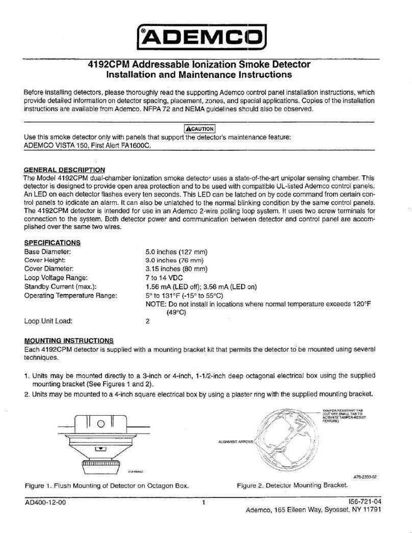
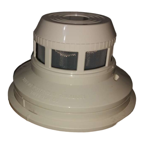
The model 4192CP dual-chamber ionization smoke detectors utifize astate of the ati unipolar sensing
chamber. These defectors aredesigned toprovlde openarea protection, andtobe usedwith compatible
UL-hstedAdemcocontrol panels only. (See note, tpage 3).
PHVSICAL AND ELECTRICAL SPECIFICATIONS
Sase Diametec 5.0 inches (12.7cm)
Cover Height 3.0 inches (7.6 cm)
Cover Dlamotex 3.t5inches (8cm)
Voltage Range: 7-11 VDC (with tKHz of modulation)
Standby Current (mm.): 320 microamps
Alarm Current Range: 230 mlcroamps min. 400 microamps mx.
Operating Temperature Range: 0° to 49°C (32°t20”F)
MOUNTING INSTRUCTIONS
Each4192CP sehes detector unit is supp~edwith amounting bracket Kt that permits the detector to be
mounted using several dfterent techniques:
1. Units may bemo”nted direcOytoa3.inch or4-inch oclago” box, l-t/2 inches deep (No, 1z50,
equivalent) electrical box using the suppbed mounting bracket (See figures 1and 2),
2. Units may bemo”ntedto 84-inch square electrical box by"sing aplaster ring wi!hfhes"pplied
mounting bracket,
3, Units may bemou"ted ~rectly to!heceifing using theplastic sc,ewanchor$ packed wifhthebrack.
et. For direct mounting, the bracket is used asatemplat@and 3116inch holes aredrilledlor the
screw anchors.
Figure 1. F1.sh Mou,,ti.gof figu,e2. Detector Mounting
Detector on Octagon Box Bracket
WIRING INSTALLATION GUIDELINES’
All widng Mustbe installed in Gompfia”cewith the National Electrical Code, local codes, a“d the authority
having jurdsdction, Proper wire gauges should be”sed, Theconduclor$ usedtoconr!ect smoke detec.
torstothe control pan81should becolor-coded toprevent witing mistakes. Improper connections can
prevent asystem from responding properly in the event of afire,
m...
“o
“. .,
,. ...” . .

For signal witing (the widng bet~een inlercQnnecteddetectors),,it is recom~ended that the wire be no
smaller !hani8gauge(l.Omm ). Wire sizes ”pto12ga”ge w#re(2,5mm )maybe used.
Forbest systemperformance the power (+) and power (-) loop wires should be twisted pair and installed
in separategro”n,ded co,nd”itorsmelded cable to protect the Ioopfrom extraneous electrical intedere”ce.
It? cable s~eld, ISprovided, the s~eld Connecffo” to and I,om the base mUSIbe CQntinUO”Sby using
wire nuts, crimping, or soldering as appropriate for arehable connection,
Wre connections are made by simply stripping about 3/6 of insulation from the end of the wire sliting
the bare endolthe wire under theclamping plate, andtightenhg theclamping plate screw. Donot loop
the wire under the clamping plate.
The zone witing of the detector should be checked for continuity, polarity, and dielectric tests
SETTING THE I.D. NUMBER FOR THE MODEL 4192CP DETECTOR
Beforelnstalling the Mode14192CP, itmustbeassi nedanldentifica ffonnumber byarrangingthe DIP
t
switch on the bottom of th@unit. Assign the num er (allocated in the control system programming
worksheet) accordng to the chafl below.
~.--...l
AD400.03.00 2156-390.00

TAMPER PROOFFEATURE
This detector includes atamper proof feature that when aclivaled prevents removal of the detector
without theuseof atool, Toactivate tMsf8ature, simpl break offthesmaller tabatthe scribed line on
t%
Ihetamper prooltab, focated onthe detector mounting racket (seefi ure2), then install thedetector.
Toremovethe detector fromthebracket oncethetamper proof feature as beenactivated, depress the
tamper prool tab Iocatedin the slot on the moumingbrackel (see Figure4) andturnthed~tec[or
counterclockwise for removal.
TESTING THE 4192CP SENSITIVITY
Note: Beforetasting, notify theproper authorities that!he smoke deteclor system isundergoing main-
te?ance, andtherefore thesystem willtemporarlly beoutofsewlce. Disable thesystemunder.
going maintenance (o prevent unwanted alarms,
Note: Beloretesting thedetector, look forthepresence of the flashing LED, Ifitdoes”otflash,
power has been lost to tfle detector, (check the wifing) or it is defective (return for repair).
WCC,,,. ,h”m,uw
:@.y,y
,,+,,,,4,
Figure4. Views Showing Position of Recessed Test Switch
Detectors must be tested alter instaflstion a“d periodic maintenance. The sensitivity of the 4192CP may
be tested in the foflowing two ways:
A. TEST SWITCH
1. Push andhold test switch lorl Osoconds,
2. Analarm should beannunciated atlhesvstem,s control orconsofe within 10seconds, Somesvs-
temswill also usethedetector' sLEDto'latch onduting the alarm. Othemise the LEDwill c&n-
finUe10flash every 10 seconds,
B, Testsensitivity fromcorltrofpanel, (Seecontrol panel testprocedure fordetailed instructions ontest
procedure, since some panels do not have this feature.)
Detectors that fail to afarm should be returned for repair,
MAINTENANCE
NOTE:BefOrestaffing, notify the pro erauthorities thatthe smoke detector system,is undergoing
Emaintenance, andlhereforet esystem wilf:emporadly beoutofsewrce. Dlsablethe loopor
system undergoing maintenance to prevent unwanted afarms.
The 4192CP is cleaned as foflows: . ..
1. Remove the detector screen and cover assembly by
,d..
“ti
.,
depressing the three fockprongs on top of the cover, rotate ,.w=
.--
the cover counterclockwise, and pull the screen and cover
assembly away from the detector (see Figure 5). ..T,.,
2. RBmovBthe screen frOmthe cover.
&
.-
3. Useavacuum cfeanertoremove d”stfrom thescree”, the
cover, and fhe sensing chamber. m
4. Aftorcfeaning, snapthe screen intothe cover, then place
the cover and screen assembly o“ the detector turning ,,.1,%.m
clockwise until it is locked In place. Figure 5. Removal of Cover and
5. Testdetector asd:scribed under SENSfTIVfTY~STfNG. Screen for Cleaning
6, NoV@theproper authorities thatth8system is backonline.
NOTE 1: Suitable for use wifh No. 4152 Point Projection Control Communicator compatibility ID: A;
maximum number of detectors persystomis 29. See N2014V1.
AD400-03-00 3156-390-00

WARNING
LIMITATIONS OF SMOKE OETECTORS
This Smokedetector! sdosigned! oactivatea ndinitiate,e me[genc actio”, b”twill dosoonlywher
2’
used lnconjunctlon w!thothere u! ment. This detector lsdes!gne Iorlnstallation inaccordancewitt
98
NFPAstandards 71,72 A,72B, 2,72 D,and72E,
Smoke detectors will network without power. ACor DCpowered smoke detactor$ will notworkil
the power supply is cut off for a“y reason.
Smoke detectOrs will not sense fires which start where smoke does not reach the detectors,
Smoke from fires in chimneys, in walls, on roofs or on the other side of closed doors may not reach the
smoke detector and alarm II,
Adetector maynotdetect allredeveloping onanother level ofabuilding. Forthis r8as0n, d8tec.
tars should be Iocatod on every fevel of abuilding.
Smoke detectors havesensing llmltatlons, too. Ionization detectors offerabroad range fire-sens-
ing capability, but they are better at detecting last, flaming fires than slow smoldering fhes,
Photoefec!ronic detectors s%nsesmoldering fires beNerlhan flaming fires. Because fires develop in
~fferent ways, and are often unpredictable in their grotih, neither type of detector is always best, and
agivendetector maynotalways provide warning of alire. fngeneral, detectors cannot bo expected
to provide warnings for fires resulting from inadequate fire protection practices, violent explosions, e>
taping gas, improper storage of flammable liquids Ike cleaning solvents, other safety hazards, or arson,
Smokedetectors cannot fast forever. Smokodetectors contain electronic pads. Evonthoughdetew
torsare made to last over 10 years, any of these PatiS could fail at any time. Therefore, test your smoke
detector system per NFPA72E atleast semiannually. Cfeanand take care ofyour smoke detectors
regularly. Taking car@ of tha fire detection system you have installed will measurably reduce your
product fiabifbyrisks,
Thisoneyear hmited Warranty isinlie” ofallothe, ex ,essw8rranties, obN atio”$orbati]ities. THERE
ARE NO EXPRESS Warranties WHfCHEXTEN8 SEYONDTHE FA/E HEREOF. ALL IMPLIED
WARRANTIES, OBLIGATIONS OR LIABILfTIES MAOE BY SELLER IN CONNECTION WITH THIS
PRODUCT, INCLUDING ANY IMPLIED WARRANTY OF MERCHANTASILl~, OR FITNESS FOR A
PARTICULAR PURPOSE OR OTHERWISE, ARE LIMITED IN OURATION TO APERfOO OF ONE
YEAR FROM THE DATE OF ORIGfNAL PURCHASE, ANY ACTION FOR BREACH OF ANY WAR.
RANTY, INCLUDING BUT NOT LIMITED TO ANY IMPLIED WARRANTY OF MERCHANTASILl~,
MUSTBE SROUGHT WITHIN I8MONTHS OF DATEOFORIGINAL PURCHASE. INNO CASE SHALL
SELLER SE LIASLE TO ANYONE FOR ANY CONSEQUENTIAL OR INCIDENTAL DAMAGES FOR
SREACHOF THIS OR ANY OTHER WARRANTY, EXPRESS OR IMPLIEO, OR uPON ANY OTHER
BASfS OF LIABILITY WHATSOEVER, EVEN IF THE LOSS OR DAMAGE fS CAUSED BY THE
SELLER’S OWN NEGLIGENCE OR FAULT. Somestates donotalfow fimitations onhowlonganim-
ted warranty lasts or tho exclusion or timifatio” of incidental or Consequentialdam~ge~,sothe~b~v~
!mitatio”orexcl”$lo” may not apply to y.”
A“..” ... .“
Table of contents
Other ADEMCO Smoke Alarm manuals

ADEMCO
ADEMCO 5808LST User manual

ADEMCO
ADEMCO 5807 User manual

ADEMCO
ADEMCO 5808LSTA User manual

ADEMCO
ADEMCO ALERT III User manual

ADEMCO
ADEMCO 5192CP User manual

ADEMCO
ADEMCO PY2700TEM User manual

ADEMCO
ADEMCO 5806 User manual

ADEMCO
ADEMCO 4192 User manual

ADEMCO
ADEMCO 5806 User manual

ADEMCO
ADEMCO 4192CPM User manual