manuals.online logo
Brands
  1. Home
  2. •
  3. Brands
  4. •
  5. ADEMCO
  6. •
  7. Smoke Alarm
  8. •
  9. ADEMCO 5808 Series User manual

ADEMCO 5808 Series User manual

5808 Series
Photoelectric
Smoke/Heat
Detector with
built-in wireless
transmitter
FEATURES
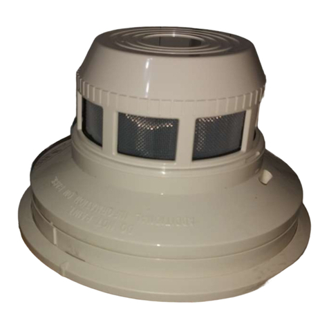
The 5808 and 5808C Commercial/Residential Photoelectric Smoke and Heat Detectors have a
built-in wireless transmitter and two concealed thermistors for heat detection. For difficult to
wire locations, room aesthetics or even hazardous materials, like asbsestos above a drop
ceiling, installation of these wireless devices provides the cost effective solution.
The 5808 and 5808C provide versatility for fire detection system designs and represents
ADEMCO’s ability to meet virtually any installation challenge using commercial wireless,
addressable or conventional detection devices.
The 5808/5808C photoelectronic smoke/heat detector with built-in wireless transmitter is
intended for use with wireless alarm systems. The 5808/5808C smoke/heat detector can be
used with 5881 series (L, M, H) for residential and 5881EH receivers for commercial
installations. The transmitter can send alarm, tamper, maintenance (see control panel
specifications) and battery condition messages to the system’s receiver. The maintenance
signal will either indicate that the photochamber requires cleaning or that the detector can no
longer respond to smoke and may need replacement. Refer to the wireless system’s
instructions for the maximum number of transmitters that can be supported.
The 5808 sounds its built-in horn when smoke reaches the detector (the LED also flashes
rapidly) or when the air temperature reaches 135°F (the LED flashes normally, about once
every 40 seconds). A message is also sent to the wireless control panel and the smoke
detector’s ID number is displayed at the console. The alarm message is transmitted every four
seconds until the smoke condition has cleared and the detector has reset. About one second
after the horn stops, a RESTORE message is transmitted to the control panel and the ID
number can be cleared from the panel. During normal, maintenance, and low battery
conditions, the LED flashes approximately once every 40 seconds.
SPECIFICATIONS
The 5808C is identical to the 5808 exept that it has no sounder to conflict with building
notification appliances.
Power source: Two-volt CR123A lithium batteries (included).
Replace with Duracell DL123A, Sanyo CR123A,
Panasonic CR123A, ADEMCO 466, or Varta
CR123.
Maintenance limits (maintenance)
is activated at either smoke level): Hot sensitivity: 0.65% + 0.15% per foot Cold
sensitivity: less than 6% per foot
Height: 2.5 inches (14 cm),
Diameter: 5.5 inches (64 mm),
Weight: 0.7 lb. (310 g)
Operating ambient temperature range: 4.4° to 37.8°C (40° to 100°F)
Operating humidity range: 5% TO 95% relative humidity
Heat sensor: 135°F fixed temperature electronic thermistors
Agency listings: UL 217; UL 268 - Residential, Commercial
Installations
5808/5808C
smoke/heat detector
An ADEMCO Group Company
The 5808 and 5808C
provide versatility for
fire detection system
designs and represents
ADEMCO’s ability to
meet virtually any
installation challenge
using commercial
wireless, addressable
or conventional
detection.
5808/5808C
Wireless Photoelectric Smoke Detector
5808/5808C
smoke/heat detector
MOUNTING INSTRUCTIONS
First, determine the best location for the smoke detector, a location that provides strong
wireless transmission paths and proper smoke detection. A GOOD TRANSMISSION PATH
MUST BE ESTABLISHED FROM THE PROPOSED MOUNTING LOCATION BEFORE
PERMANENTLY INSTALLING THE DETECTOR. To check, perform the test described in the
TESTING TRANSMITTER SIGNAL section of this
manual. To mount the detector:
1. Once a suitable location has been determined,
install the mounting bracket on the ceiling or on the
wall (if local ordinances permit). Use the two screws
and anchors provided.
2. Prior to mounting the detector to the mounting
bracket, the system must “enroll” the detector’s ID.
See the Programming section for the steps to follow.
3. Turn the detector immediately after completing the installation and refer to the control
system’s instructions for additional information concerning the use of wireless smoke
detectors.
Tamper protection
This detector has a built-in tamper switch that will cause a CHECK signal to be displayed at
the console of the detector if it is removed from its installation bracket. The mounting bracket
can also be made tamer-proof by breaking off the smaller tab at the scribed line, thus
preventing removal of the detector without a tool. To remove the detector, use a small
screwdriver to depress the tamer-proof tab and turn the detector counter-clockwise.
Testing
Note: Before testing, notify the proper authorities that the smoke detector system is
undergoing maintenance and will temporarily be out of service. Disable the zone or system
undergoing maintenance to prevent unwanted alarms.
Detectors must be tested after installation and following periodic maintenance. The 5808
may be tested as follows:
A. Test switch
1. A recessed test switch is located on the detector housing
2. Push and hold the recessed test switch with a 0.1” maximum diameter tool (an
alien wrench or small screwdriver)
B. Test module (Model No. MOD400R)
The MOD400R test module can be used with a DMM or analog voltmeter to check the
detector sensitivity as described in the test module’s manual.
An ADEMCO Group Company
C. Smoke entry test
Hold a smoldering punk stick or cotton wick at the side of the detector and gently
blow smoke through the detector until the unit alarms.
D. Direct heat method (hair dryer of 1000-1500 watts)
Direct the heat toward either side thermistor. Be sure to hold the heat source about 12
inches from the detector to avoid damage to the plastic. The detector will reset only
after it has time to cool.
Smoke detection testing is recommended for verifying system protection capability.
A detector that fails to activate with any of these tests should first be cleaned. If the
detector still fails to activate, return for repair.
Notify the proper authorities that the system is back on line.
Testing transmitter signal
Note: Remove battery tab before installation.
This test should be performed before installation to determine a strong communication path
with the control panel and after installation is complete. Also, the owner/user should test
the unit at least weekly.
1. Activate the wireless system’s TEST mode from the console.
2. Depress and hold the smoke detector’s TEST switch and the detector should immediately
transmit and alarm signal to the control panel. The built-in horn will start to sound about
2.5 seconds after depressing the button.
3. The wireless system’s console should emit at least three audible sounds when the alarm
transmission is received and will display the transmitting detector’s ID number.
4. When the console has received the test signal, release the TEST switch. The horn will
immediately stop and a few seconds later, the detector’s ID number will clear from the
console display.
5. If the console does not respond as noted, check the polarity of the batteries and be sure
they are fresh. If this is an initial installation, try moving the detector to another location
that provides proper reception. Also, be sure that the detector’s ID has been “enrolled”
by the control panel (see programming). Then, repeat the test.
6. Turn off the system’s TEST mode from the console (security code + off).
An ADEMCO Group Company
5808/5808C
smoke/heat detector
165 Eileen Way, Syosset, New York 11791 • Copyright © 1997 Pittway Corporation
ADEMCO is an ISO9001 Registered Company
L/5808C/D 1/99
Ordering Information
Part No. Description
5808 Smoke/Heat
Detector
w/Sounder
5808C Smoke/Heat
Detector
Maintenance
Note: Before removing the detector, notify the proper authorities that the smoke detector
system is undergoing maintenance and will be out of service. Disable the zone or system
undergoing maintenance to prevent unwanted alarms.
1.. Remove the detector cover by placing a small bladed screwdriver in the cover removal
slot and twisting it slightly until the cover can be turned counterclockwise for removal.
2. Remove the screen by pulling it straight out. Vacuum the screen thoroughly.
3. Clean the black vaned chamber piece by vacuuming or blowing out dust and particles.
4. To reinstall the screen, rotate the screen on the housing until it drops into the alignment
slots. Carefully push the screen onto the base, making sure it fits tightly to the chamber.
Replacement screens are available (order part number RS23).
5. Replace the cover by rotating it clockwise until it locks into place.
6. Reinstall the detector into the system, enable the system operation, and notify the proper
authorities that the system is back on line.
To keep your equipment in excellent working order, ongoing maintenance is required per the
manufacturer’s recommendations and UL and NFPA standards. At a minimum, the
requirements of Chapter 7 of NFPA 72, the National Fire Alarm Code, shall be followed. A
preventative maintenance agreement should be arranged through the local manufacturer’s
representative. Though smoke detectors are designed for long life, they may fail at any time.
Any smoke detector, fire alarm equipment, or any component of that system which fails
shall be repaired or replaced as soon as possible.
An ADEMCO Group Company
5808/5808C
smoke/heat detector

This manual suits for next models

1

Other ADEMCO Smoke Alarm manuals

ADEMCO PY2700TEM User manual

ADEMCO

ADEMCO PY2700TEM User manual

ADEMCO 5808LSTA User manual

ADEMCO

ADEMCO 5808LSTA User manual

ADEMCO 5806 User manual

ADEMCO

ADEMCO 5806 User manual

ADEMCO 4192 User manual

ADEMCO

ADEMCO 4192 User manual

ADEMCO 5808 User manual

ADEMCO

ADEMCO 5808 User manual

ADEMCO 5192CP User manual

ADEMCO

ADEMCO 5192CP User manual

ADEMCO 4192CP Instruction Manual

ADEMCO

ADEMCO 4192CP Instruction Manual

ADEMCO 5808LST User manual

ADEMCO

ADEMCO 5808LST User manual

ADEMCO 5806 User manual

ADEMCO

ADEMCO 5806 User manual

ADEMCO 5707 User manual

ADEMCO

ADEMCO 5707 User manual

ADEMCO 4192CPM User manual

ADEMCO

ADEMCO 4192CPM User manual

ADEMCO ALERT III User manual

ADEMCO

ADEMCO ALERT III User manual

ADEMCO 5807 User manual

ADEMCO

ADEMCO 5807 User manual

Popular Smoke Alarm manuals by other brands

BRK electronic 83R-UK user manual

BRK electronic

BRK electronic 83R-UK user manual

Siemens FDA2 Series Planning, Mounting

Siemens

Siemens FDA2 Series Planning, Mounting

x-sense XS01-WT user manual

x-sense

x-sense XS01-WT user manual

Masterbuilt MPS250S manual

Masterbuilt

Masterbuilt MPS250S manual

Kidde P12040 user guide

Kidde

Kidde P12040 user guide

SANJIANG JTY-GD-S839 instruction manual

SANJIANG

SANJIANG JTY-GD-S839 instruction manual

Bosch FMM‑325A Series manual 

Bosch

Bosch FMM‑325A Series manual 

Essence Security ES700SK2 Installation

Essence Security

Essence Security ES700SK2 Installation

Firex CCPB user manual

Firex

Firex CCPB user manual

Vitek VT-SMKC1 Specifications

Vitek

Vitek VT-SMKC1 Specifications

Vesta SD-29-SC-AC Series quick start guide

Vesta

Vesta SD-29-SC-AC Series quick start guide

CAPIDI CAP388B user manual

CAPIDI

CAPIDI CAP388B user manual

Ei Electronics Ei161RC Ionisation product manual

Ei Electronics

Ei Electronics Ei161RC Ionisation product manual

pyrexx PX-1 Operating, installation and maintenance manual

pyrexx

pyrexx PX-1 Operating, installation and maintenance manual

Cooper Scantronic 509r installation manual

Cooper

Cooper Scantronic 509r installation manual

Mobeye CM2400 user manual

Mobeye

Mobeye CM2400 user manual

hyfire HFW-PA-05 manual

hyfire

hyfire HFW-PA-05 manual

BRK electronic 650M owner's manual

BRK electronic

BRK electronic 650M owner's manual

manuals.online logo
manuals.online logoBrands
  • About & Mission
  • Contact us
  • Privacy Policy
  • Terms and Conditions

Copyright 2025 Manuals.Online. All Rights Reserved.