adesto SM2400-EVK2 User manual

UG-SM2400–-174A–-12/2018
SM2400-EVK2 Evaluation Kit
User’s Guide
Communication Technology by:
Semitech Semiconductor

2SM2400-EVK2 User’s Guide
UG-SM2400–-174A–-12/2018
This publication contains proprietary information which is subject to change without notice and is supplied ‘as
is’, without any warranty of any kind.
Revision History
Revision Number Date Tasks
A 12/2018 SM2400-EVK2 Evaluation Kit User’s Guide initial release

3SM2400-EVK2 User’s Guide
UG-SM2400–-174A–-12/2018
Table of ontents
1 Introduction 4
2 Factory Configuration Options 4
3 Package Contents 5
4 SM2400-EVK2 System Overview 6
4 1 SM2400-EVK2 Hardware Configuration 7
4 2 SM2400 Firmware 8
5 SM2400-EVK2 Hardware Components 9
5 1 IEC Connector 9
5 2 Mini-USB Connector 9
5 3 Reset Button 9
5 4 External DC Power Supply 10
5 5 Host Interface 11
6 Evaluation and Setup 12
6 1 General Setup and Connection 12
6 2 Download Firmware 13
6 3 Evaluation PHY/Pass-through 14
6 3 1 Evaluate Standardized PHY 15
6 3 2 Evaluate XXR PHY 17
6 3 3 Evaluate ASCII Pass-through 19
6 3 4 Evaluate SunSpec with XXR 21
6 4 Evaluate Mesh Network 24
6 4 1 Evaluate PRIME Network 25
6 4 2 Evaluate G3-PLC/IEEE ASL 36
6 4 3 Evaluate G3-PLC/IEEE MAC 41
6 4 4 Evaluate XXR with SMESH MAC 43
6 5 Troubleshooting 47
6 5 1 Problem — Cannot Connect to the Serial Port of the PC 47
6 5 2 Problem — Can't Receive Any Packets 47
6 5 3 Analyzing the Power Line Condition using Channel Monitor 47
6 5 4 Check the Raw Packet Data from the Command Log 49

4SM2400-EVK2 User’s Guide
UG-SM2400–-174A–-12/2018
1. Introduction
The second generation SM2400 Evaluation Kit (EVK2) provides an evaluation platform for the SM2400 universal
Narrowband Power Line Communication (NPLC) modem It supersedes the first generation SM2400 EVK
However, both versions utilize the same N-PLC modules and are interchangeable in terms of firmware The
SM2400-EVK2 is designed to evaluate and develop various SM2400-based N-PLC solutions, including all major
OFDM based N-PLC standards, such as PRIME, G3-PLC and IEEE 1901 2, as well as proprietary modes by
loading different firmware versions
The SM2400-EVK2 includes a PC-based GUI application (SM2400Control.exe) that enables comprehensive
configuration and control of the SM2400 modem and monitoring/testing of the communication performance
Features of the SM2400-EVK2 include:
• A complete N-PLC node solution with no external components needed
• Mini USB connection for both UART and SPI interface to the SM2400 PLC transceiver as well as
direct UART connection
• IEC C8 power connection
• Built-in power line coupling circuit
• Use external DC supply
• LED indicators for transmit and receive
• Programmable PRIME/G3-PLC/IEEE 1901 2/XR/XXR firmware
• JTAG debugging
2. actory Configuration Options
The EVK can be factory-configured with numerous line driver and frequency band options For each part number,
the last two characters indicate the line driver and frequency band used For example, SM2400-EVK2M1-A In
this case, the number 1 and the letter A will change based on the line driver and frequency band used The
SM2400-EVK2 supports all combinations shown in Figure 1
igure 1. SM2400-EVK2 actory Configuration Options
SM2400-EVK2Mn-x
1 = Texas Instruments Line Driver
2 = Intersil Line Driver
3 = Discrete Line Driver
A = CEN-A Frequency Band
B = CEN-B/BC Frequency Band
C = FCC Frequency Band
D = Full Band
4 = SGM Line Driver
5 = OnSemi Line Driver

5SM2400-EVK2 User’s Guide
UG-SM2400–-174A–-12/2018
3. Package Contents
Each SM2400-EVK2 Evaluation Kit contains:
• 1 x SM2400-EVK2 base board
• 1 x SM2400-EV1Mn-A or 1 x SM2400-EV1Mn-B or 1 x SM2400-EV1Mn-C or 1 x SM2400-EV1Mn-D
module board (same form factor as the SM2400 EVK) — The ‘n’ in the part number refers to the line
driver and can be a value of 1, 2, 3, 4, or 5 Refer to Figure 1 for more information
• SM2400 N-PLC transceiver (located on the module board)
• 1 x 12V-DC or 15V-DC plug pack
• 1 x mini USB cable
Note: At least two SM2400-EVK2 systems are needed for power line communication evaluation

6SM2400-EVK2 User’s Guide
UG-SM2400–-174A–-12/2018
4. SM2400-EVK2 System Overview
The SM2400 N-PLC transceiver is located on the SM2400-EV1Mn-x module board which has the same form
factor as the module used in SM2400-EVK The main difference between the SM2400-EVK and the SM2400-
EVK2 is the form factor of the base board As shown in Figure 2, the SM2400-EV1Mn board containing the
SM2400 N-PLC device is connected to the SM2400-EVK2 base board to comprise the SM2400-EVK2 Evaluation
Kit
igure 2. SM2400-EVK2 Components (Top View)
From time to time new firmware packages are released that demonstrate new features and applications, such as
Serial-to-PLC adapter The SM2400-EVK2 includes a PC-based GUI application (SM2400Control.exe) that
enables comprehensive configuration and control of the SM2400 modem and monitoring/testing of the
communication performance
This document describes the SM2400-EVK2 and the SM2400Control GUI software
DC Plug
SM2400
UART USB connector
IEC C8
Plug
SM2400-EVK2
SM2400-EV1Mn

7SM2400-EVK2 User’s Guide
UG-SM2400–-174A–-12/2018
4.1 SM2400-EVK2 Hardware Configuration
The SM2400-EVK2 Evaluation Kit consists of two boards:
1 The SM2400-EVK2Mn base board includes an IEC C8 plug, a DC jack, two PLC module connectors, a
communication interface (USB), and a reset button
2 The SM2400-EV1 PLC module includes the SM2400 device, as well as SPI Flash memory, an Analog Front-
End (AFE) circuit, and a coupling circuit The module comes with one the following options depending on the
desired operational band:
• The SM2400-EV1Mn-A includes an integrated power amplifier and a coupling circuit for the CENELEC
A band The ‘n’ in the part number refers to the line driver Refer to Figure 1 for more information
• The SM2400-EV1Mn-B includes an integrated power amplifier and a coupling circuit for the CENELEC
B and C bands The ‘n’ in the part number refers to the line driver Refer to Figure 1 for more
information
• The SM2400-EV1Mn-C includes an integrated power amplifier and coupling circuit for the FCC band
The ‘n’ in the part number refers to the line driver Refer to Figure 1 for more information
• The SM2400-EV1Mn-D includes an integrated power amplifier and coupling circuit for the Full band
from 35 kHz to 500 kHz The ‘n’ in the part number refers to the line driver Refer to Figure 1 for more
information
The above modules are used as an example throughout this document From time to time Adesto releases
additional variants of the module with different part numbers that use alternative power amplifiers (Line Drivers),
which can also be used in conjunction with the SM2400-EVK2Mn base board without any other changes to the
setup
The PC interface to the SM2400-EVK2 is through a standard mini-USB connector A standard IEC C8 plug is
used as the main power connector to accommodate different types of main outlets and a 12VDC/15VDC plug
pack is used to provide the DC power to the EVK
Typically, in order to demonstrate communication over a power line, two SM2400-EVK2 boards are required The
two EVK’s can communicate with each other by connecting both to the same power line, as illustrated in Figure 3
Each EVK is connected via a USB port to a PC running the SM2400Control application The application is used
to control and monitor the communication To communicate properly, both EVK’s must be running the same
firmware load (PHY and protocol) Refer to the following section for a list of firmware loads
Note that the SM2400-EVK2 can also be used to test interoperability with other devices In such cases, one EVK
is sufficient It must be connected to the same power line as the other devices and run the same protocol (e g
PRIME or G3-PLC)

8SM2400-EVK2 User’s Guide
UG-SM2400–-174A–-12/2018
igure 3. Multiple SM2400-EVK2 Connections
4.2 SM2400 irmware
Since the SM2400 N-PLC transceiver supports many communication schemes, the SM2400-EVK2 is offered with
different firmware loads that support various communication schemes and protocols Each offering is a separate
firmware version that can be downloaded to the SPI Flash available on the EVK via the USB cable using the
SM2400Control GUI software The SM2400Control GUI can also be used as the controller to allow evaluation
and debugging as well as early system integration The firmware loads are independent of any EVK specifics and
are eventually used in the final products without any changes
The SM2400-EVK2 firmware offerings include PRIME PHY, PRIME MAC, G3 PHY, G3 MAC, and XXR modes,
and IEEE 1901 2 high-band (FCC) PHY and MAC From time to time new firmware packages are added that
implement new schemes or applications
The SM2400-EVK2 firmware versions support all major OFDM standards including PRIME, G3-PLC and IEEE
1901 2 high-band as well as the robust proprietary XR and XXR modes Each standard and proprietary mode is
typically available in the following configurations to allow different levels of testing:
• PHY only for easiest setting and performance evaluation
• PHY+ MAC that enables establishing and evaluating network performance
• PHY+ ASL that also includes Adaptation Layer for a complete application
Lastly, each communication scheme is typically available for different operational bands, such as, CEN-A or FCC
Below is a complete list of the firmware versions available for the SM2400-EVK2 From time to time Adesto
releases additional firmware versions for new standards and communication modes
Table 1. SM2400-EVK2 irmware Versions
PRIME PHY (CEN A) IEEE 1902 2 PHY (CEN-B)
PRIME PHY + MAC (CEN A) IPv4 IEEE 1901 2 PHY + MAC (CEN-B)
PRIME PHY + MAC (CEN A) IPv6 IEEE 1901 2 PHY + ASL (CEN-B)
G3-PLC PHY (CEN A) IEEE 1901 2 PHY (CEN-C)
G3-PLC PHY + MAC (CEN A) IEEE 1901 2 PHY + MAC (CEN-C)
G3-PLC PHY + ASL (CEN A) IEEE 1901 2 PHY + ASL (CEN-C)
G3-PLC PHY + MAC (CEN B) IEEE 1901 2 PHY (CEN-BC)
G3-PLC PHY + ASL (CEN B) IEEE 1901 2 PHY + MAC (CEN-BC)
SM2400 EVK2 #1
SM2400 EVK2 #2

9SM2400-EVK2 User’s Guide
UG-SM2400–-174A–-12/2018
5. SM2400-EVK2 Hardware Components
There are a few external connectors that can be used to interface to the SM2400-EVK2 Evaluation Kit
5.1 IEC Connector
The IEC C8 plug is used to connect the SM2400-EVK2 to the power line via a coupling circuit Looking into the
connector, the right pin is neutral and left pin is line/active as shown in Figure 4
igure 4. SM2400-EVK2 IEC Connector
5.2 Mini-USB Connector
The mini-USB connector is used to connect a host (i e PC) to the SM2400-EVK2 The PC connects to the mini-
USB connector to access the SM2400-EVK2 via an on-board USB-to-serial converter The mini-USB connector
(UART) is shown in the Figure 5
5.3 Reset Button
The reset button is located beside the mini-USB connector as shown in Figure 6
G3-PLC PHY (FCC) IEEE 1901 2 PHY + ASL (CEN-BC)
G3-PLC PHY (FCC) IEEE 1901 2 PHY (FCC)
G3-PLC PHY + MAC (FCC) IEEE 1901 2 PHY + MAC (FCC)
G3-PLC PHY + ASL (FCC) IEEE 1901 2 PHY + ASL (FCC)
IEEE 1901 2 PHY (CEN-A) XXR PHY
IEEE 1901 2 PHY + MAC (CEN-A) XXR PHY + SUNSPEC
IEEE 1901 2 PHY + ASL (CEN-A) XXR PHY + SMESH
Table 1. SM2400-EVK2 irmware Versions (continued)
Line Neutral

10SM2400-EVK2 User’s Guide
UG-SM2400–-174A–-12/2018
igure 5. SM2400-EVK2 USB UART Connector
igure 6. SM2400-EVK2 Reset Button
5.4 External DC Power Supply
The SM2400-EVK2 is powered by an external 15V/1A plug pack to 2 1mm DC plug H1 as shown in Figure 7 and
it can also work with higher DC level up to 28V, which is useful in order to increase the line driver gain on the PLC
module
The DC-DC converter circuits consist of a 3 3V linear regulator (U14) that provides low ripple, low noise on the
DC power rails to keep signals from being too noisy
mini-USB (UART)
Reset

11SM2400-EVK2 User’s Guide
UG-SM2400–-174A–-12/2018
igure 7. SM2400-EVK2 DC Plug
5.5 Host Interface
An external host can be connected to the SM2400-EVK2 via the UART interface on the host interface header P1
of the SM2400-EVK2 base board as shown in Figure 8 When this interface is used, a mini-USB cable should be
unplugged from the mini-USB connector shown in Figure 5 For example, connect TXD, RXD and GND of a FTDI
USB-to-serial cable to the EX-UTX, EX-URX and GND pins on the P1 header instead of using the mini-USB
cable
igure 8. Host Interface Header P1
DC plug

12SM2400-EVK2 User’s Guide
UG-SM2400–-174A–-12/2018
6. Evaluation and Setup
6.1 General Setup and Connection
The instructions below describe the general setup for a SM2400-EVK2M1 application
• The SM2400-EVK2 was designed to help testing and evaluating the features and capabilities of the SM2400
N-PLC modem using the SM2400Control GUI
• For PRIME or G3-PLC CENELEC-A band, evaluation ensures that the SM2400-EV1Mn-A modules for
CENELEC-A band are used
• For G3-PLC CENELEC-B band or IEEE 1901 2 CENELEC-B band, evaluation ensures that the
SM2400-EV1Mn-B modules for CENELEC-B band are used
• For G3-PLC FCC or IEEE 1901 2 FCC, evaluation ensures that the SM2400-EV1Mn-C modules for the FCC
band are used XR and XXR modes can be configured to operate in any of the bands
• Plug both EVK’s to the same power-line and connect two SM2400-EVK2 boards to two PC’s through USB
cables as shown in Figure 3
For registered customers, SM2400Control GUI application can be downloaded from either the Semitech website:
http://www semitechsemi com/solutions/sm9420 php or Adesto the website:
https://www adestotech com/products/power-line-communications/ Start the SM2400Control GUI application by
double clicking the executable file Upon running the program, the following window is displayed:
igure 9. SM2400 Control Main Display Window

13SM2400-EVK2 User’s Guide
UG-SM2400–-174A–-12/2018
The SM2400-EVK2 can be automatically connected to the serial port through the on-board CP2110 HID USB-to-
UART BRIDGE Once it is connected, the serial number of the CP2110 on the EVK is shown (red box below) on
the top of GUI menu bar and under the Dev board tab
igure 10. Locating the Serial Number
If the EVK is not automatically connected, click Scan to find the CP2110 serial number, and then click Connect
6.2 Download irmware
For registered customers, SM2400 firmware can be downloaded from either the Semitech website:
http://www semitechsemi com/solutions/sm9420 php or the Adesto website:
https://www adestotech com/products/power-line-communications/
To download/upgrade the firmware of the SM2400-EVK2 using the SM2400Control GUI via the USB cable, follow
the steps below:
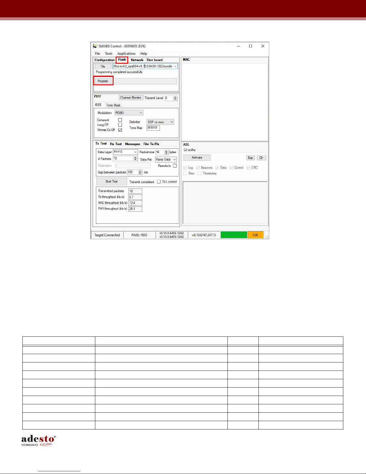
1 Click the Flash tab The following screen shot is displayed
14SM2400-EVK2 User’s Guide
UG-SM2400–-174A–-12/2018
igure 11. irmware Download Procedure — Click the Flash Tab
2 Click File to find the firmware (e g img-g3-fcc-asl-evk2_opa564-v0 10 0 8439-1262 bundle downloaded
from one of the above websites)
3 Click Program Flash
4 Wait until the Programming Completed Successfully message is displayed
6.3 Evaluation PHY/Pass-through
Firstly, download the right PHY/Passthru firmware to two EVKs Following are the list of the PHY firmware:
Table 2. irmware Download Options
Protocol irmware Name Band Module P/N
PRIME PHY img-passthru-prime-bc-evk2_opa564- vxxx bundle CEN A SM2400-EV1Mn-A
G3-PLC CEN A PHY img-passthru-g3-cena-evk2_opa564- vxxx bundle CEN A SM2400-EV1Mn-A
G3-PLC CEN B PHY img-passthru-g3-cenb-evk2_opa564- vxxx bundle CEN B SM2400-EV1Mn-B
G3-PLC FCC PHY img-g3-fcc-asl-evk2_opa564- vxxx bundle FCC SM2400-EV1Mn-C
IEEE 1901 2 CEN-A PHY img-passthru-ieee-cena-evk2_opa564- vxxx bundle CEN A SM2400-EV1Mn-A
IEEE 1901 2 CEN-B PHY img-passthru-ieee-cenb-evk2_opa564- vxxx bundle CEN B SM2400-EV1Mn-B
IEEE 1901 2 CEN-BC PHY img-passthru-ieee-cenbc-evk2_opa564- vxxx bundle CEN BC SM2400-EV1Mn-B
IEEE 1901 2 CEN-C PHY img-passthru-ieee-cenc-evk2_opa564- vxxx bundle CEN C SM2400-EV1Mn-B
IEEE 1901 2 FCC PHY img-passthru-ieee-fcc-evk2_opa564- vxxx bundle FCC SM2400-EV1Mn-C
XXR PHY img-passthru-xxr-evk2_opa564- vxxx bundle FCC SM2400-EV1Mn-C

15SM2400-EVK2 User’s Guide
UG-SM2400–-174A–-12/2018
6.3.1 Evaluate Standardized PHY
To evaluate a standardized PHY (e g PRIME PHY, G3 PHY or IEEE PHY), download the same PHY/pass-
through firmware to both EVK's, under the Configuration tab, click the Mode pull down button to get the right
protocol (e g G3 FCC)
One node should be configured as the transmitter (Tx) and the other as the receiver (Rx)
1 Click x est to set the first GUI/EVK as Tx node The SM2400Control GUI allows for a number of options to
be configured for the Tx node as follows:
• Set Transmit Level (from highest level 0dB to lowest level -21dB)
• Set Modulation (ROBO/BPSK/QPSK/8PSK, depending on the protocol)
• Write the number of packets to be sent from Tx Test tab e g 100 (0 means continuously sending
packets without stop)
• Change the packet size if needed
• Select Data pattern
Click the Start est button on the Tx Test tab from the Tx window and monitor the results from the Rx Test tab
from the Rx window as shown in the following screen shot
igure 12. Evaluate Standardized PHY — Click Tx Test
2 Set the second GUI/EVK as Rx node
• From Mode pull down menu, select the same protocol as the Tx (e g G3 FCC)

16SM2400-EVK2 User’s Guide
UG-SM2400–-174A–-12/2018
• Click the Rx est tab as shown in Figure 13
• When the Tx node is transmitting packets, the results (e g received packets) should be automatically
displayed on the GUI of the Rx EVK
• Click Plot Results button as shown in Figure 14 to get a bar chart of the received packets, SNR and
RSSI values
• Click Clear Results if needed
igure 13. Evaluate Standardized PHY — Rx Test Tab Results

17SM2400-EVK2 User’s Guide
UG-SM2400–-174A–-12/2018
igure 14. Evaluate Standardized PHY — Click Plot Results Tab to Plot Received Packets
6.3.2 Evaluate XXR PHY
Use the same method to download the XXR PHY firmware to two EVKs And then follow the following steps to
evaluate XXR PHY
1 Click x est to set the first GUI/EVK as Tx node The default XXR PHY configuration is shown below:
igure 15. Evaluate XXR PHY — Click Tx Test to Set Tx Mode

18SM2400-EVK2 User’s Guide
UG-SM2400–-174A–-12/2018
The SM2400Control GUI allows for a number of options to be configured for the XXR mode as follows:
• Set Transmit Level (from highest level 0dB to lowest level -21dB)
• Set Modulation: BPSK-Rep4/BPSK-Rep3/BPSK-Rep2/BPSK (PLC performance can be improved by
selecting the redundancy BPSK-Rep4 is the most robust mode)
• Click Set button to apply the XXR configuration changes
• Write the number of packets to be sent from Tx Test tab e g 100 (0 means continuously sending
packets without stop)
• Change the packet size if needed
• Select Data pattern
2 Set the second GUI/EVK as Rx node
• Use the same XXR configurations as the Tx node
• Click Set button to apply the XXR configuration changes
• Check the received packet results from the Rx Test tab
igure 16. Evaluate XXR PHY — Click Rx Test to Check Rx Packets

19SM2400-EVK2 User’s Guide
UG-SM2400–-174A–-12/2018
6.3.3 Evaluate ASCII Pass-through
‘Ascii pass-through’ is a variant of pass-through firmware to provide a remote terminal over the PLC line
The ‘Ascii pass-through’ copies all ASCII characters, which are received on the UART, verbatim to the PLC line,
and, conversely, forwards all ASCII characters received from the PLC line verbatim to the UART
The transmission to the power line in ‘ASCII pass-through’ is triggered by reception of a special ASCII character,
normally End-Of-Line or Carriage Return
The configuration in ‘Ascii pass-through’ can be changed using AT commands
1 Supported AT Commands
+++: Switch to COMMAND mode (default mode) |
ATO: Switch to DATA mode
ATS: Set/Get Register
ATZ: Reboot
AT&F: Restore factory defaults
ATPHY: Send Rx configuration to PHY (includes TxLevel, LongCP, FEC enable, Sequence Enable, Band,
Redundancy, Modulation, and SubCarriers)
Note: When running the ASCII PASSTHRU project for the first time on the board which had other projects loaded
before, it is important to run AT&F command followed by ATZ command This is needed to write ASCII-specific
default settings to the Flash
2 Registers available for ATS command (Set/Get Register)
37: UART baud rate
100: Modulation code
Where
Robust: 0
BPSK: 1
QPSK: 2
8-PSK: 3
101: Bits Per Baud
102: Repetition
103: Number Frequencies
104: Convolution Code Enable
105: Tone Map
106: Coherent mode enable
107: Delimiter
108: On/Off Mode
109: Band Select
110: Sub-Carriers
111: FCC enable
Availability and exact meaning of some registers depend on PHY PLC protocol
3 Firmware
passthru with "ascii" suffix
4 Supported baud rates
modes 0 through 4: 600
mode 5: 1200
mode 6: 2400
modes 7 and 8: 4800

20SM2400-EVK2 User’s Guide
UG-SM2400–-174A–-12/2018
mode 9: 9600
modes 10 and 11: 14400
Note: higher baud rates might not be standard allocations
mode 12: 19200
mode 13: 38400
mode 14: 57600
mode 15: 115200
mode 16: 230400
mode 17: 375000
mode 18: 625000
5 Factory Defaults
UART baud rate: 115200 (mode 15)
6 PHY-specific defaults
a Prime defaults
Modcod = 0
bitsPrBaud = 1
repetition = 1
NumFreq = 97
ConvCodeEn = 1
b XXR defaults
Modcod = 1
bitsPrBaud = 1
repetition = 4
Subc2200 = 30405060
c G3 defaults
Modcod = 0
bitsPrBaud = 1
repetition = 4
ToneMap = 0x03F
Coherent = 1u
Delimiter = 0
d IEEE defaults
Modcod = 0
bitsPrBaud = 1
repetition = 4
Delimiter = 0
OnOffMode = 1
7 Example
a Change the UART baud rate
• Download the img-passthru-g3-ascii-fcc-evk2_opa564-v0.10.0.8724-1321.bundle to two EVKs using
the SM2400Control GUI;
• Connect two serial terminals to two EVKs via a USB-to-serial cable; open the connection at 115200
bps baud rate
Other manuals for SM2400-EVK2
1
Table of contents
Other adesto Motherboard manuals


