FIC FR33E User manual

FR33E
MAINBOARD
MANUAL
DOC No.: M01503
Rev. :A0
Date : 9, 2001
Part No. : 25-11620-00

Handling Precautions
Warning:
1. Static electricity may cause damage to the integrated circuits on
the motherboard. Before handling any motherboard outside of its
protective packaging, ensure that there is no static electric charge
in your body.
2. There is a danger of explosion if the battery is incorrectly
replaced. Replace only with the same or an equivalent type
recommended by the manufacturer.
3. Discard used batteries according to the manufacturer’s
instructions.
4. Never run the processor without the heatsink properly and firmly
attached. PERMANENT DAMAGE WILL RESULT!
Observe the following basic precautions when handling the motherboard
or other computer components:
nWear a static wrist strap which fits around your wrist and is
connected to a natural earth ground.
nTouch a grounded or anti-static surface or a metal fixture such as a
water pipe.
nAvoid contacting the components on add-on cards, motherboards,
and modules with the golden fingers connectors plugged into the
expansion slot. It is best to handle system components by their
monting brackets.
The above methods prevent static build-up and cause it to be discharged
properly.
Trademark
All trademarks mentioned in this manual are registered properly of
the respective owners.
Handling Precautions
This manual may not, in whole or in part, be photocopied, reproduced,
transcribed, translated, or transmitted in whatever form without the
written consent of the manufacturer, except for copies retained by the
purchaser for personal archival purposes.
Notice

i
TableofContents
Table of Contents
Chapter 1 Overview
Package Checklist ...................................................................... 1-2
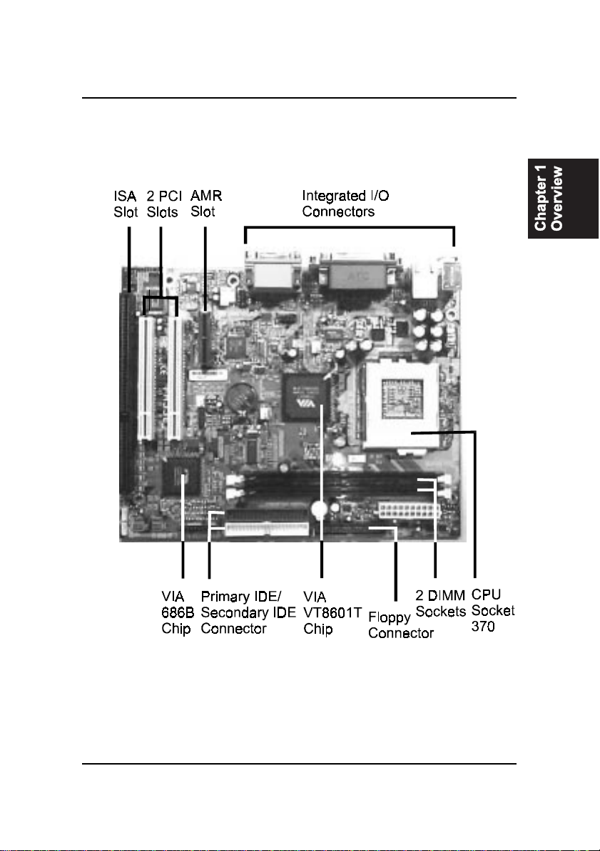
The FR33E Mainboard .............................................................. 1-3
Main Features ................................................................................ 1-4
ACPI Ready ................................................................................... 1-6
FIC Unique Innovation for Users (NOVUS) -
Enhanced Mainboard Features and System Support .................... 1-6
Chapter 2 Installation Procedures
Quick Reference (from Page 2-2 to 2-4) .......................................... 2-2
Mainboard Layout .................................................................... 2-2
1). Clear CMOS Enable ...................................................... 2-3
2). Front Panel Block Cable Connection ............................ 2-3
3). CPU Fan Installation .................................................... 2-4
1). Set System Jumpers .................................................................. 2-4
Clear CMOS: CLR_CMOS ................................................. 2-5
2). Install Memory Modules .......................................................... 2-5
3). Install the CPU .......................................................................... 2-6
4). Install Expansion Cards ............................................................. 2-7
5). Connect Devices ....................................................................... 2-9
Floppy Diskette Drive Connector: ..................................... 2-9
IDE Device Connectors ..................................................... 2-10
ATX Power Connector ...................................................... 2-10
Fan Connectors ................................................................. 2-11
Wake-On-LAN Connector ................................................. 2-11
Wake-On-Ring Connector ................................................. 2-12
CD Audio-In Connector .................................................... 2-12
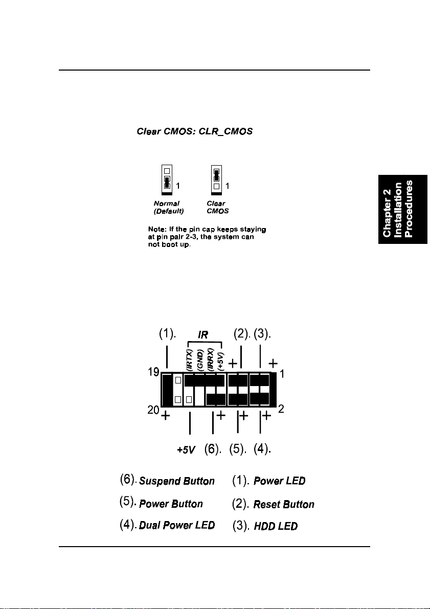
Front Panel Block and Speaker Connector ........................ 2-13
PS/2 Keyboard and Mouse Connector ............................. 2-14
LAN Jack ........................................................................... 2-14
Quick Reference (German) G-1
Quick Reference (French) F-1
Quick Reference (Spanish) S-1
Quick Reference (Japanese) J-1
Quick Reference (Chinese) C-1
Quick Reference (Simplified Chinese) |||||||||||||SC-1

ii
FR33EMainboardManual
GAME/MIDI Connector .................................................... 2-17
SPDIF Connector .............................................................. 2-18
Universal Serial Bus Connectors ....................................... 2-15
Serial Port Connectors ....................................................... 2-15
Video Graphics Accelerator Connector .............................. 2-16
Printer Connector .............................................................. 2-16
Audio I/O Jacks ................................................................ 2-17
Chapter 3 BIOS Setup
CMOS Setup Utility ....................................................................... 3-1
Standard CMOS Setup ................................................................... 3-2
Advanced BIOS Features .............................................................. 3-4
Advanced Chipset Features .......................................................... 3-7
Integrated Peripherals .................................................................... 3-10
Power Management Setup ............................................................. 3-15
PnP/PCI Configurations ................................................................. 3-19
PC Health Status ............................................................................ 3-21
Frequency/Voltage Control ............................................................ 3-22
Load Fail-Safe Defaults .................................................................. 3-23
Load Optimized Defaults ................................................................ 3-23
Supervisor/User Password ............................................................ 3-23
Save and Exit Setup ........................................................................ 3-24
Exit without Saving ........................................................................ 3-24

1 - 1
Overview
Overview
Chapter 1
The new Micro ATX, Socket 370 mainboard is a low cost all-in-on Intel®solu-
tion that supports a full range of the latest generation Intel®and Cyrix®pro-
cessors. New lightening fast processors from Intel of up to 1.26GHz and up*
are supported with Front Side Bus speeds of 66/100/133 MHz.
(*: not tested yet)
The VIA VT8601T Apollo PLE133T®on this mainboard coworks with Intel
Celeron®, Cumine®, Tualatin®and Cyrix processors. With integrated AGP 2D/
3D graphics accelerator, features AC97 codec, and other onboard audio fea-
ture that embedded in VIA 686B®Super South, the mainboard offers an excel-
lent media environment.
Support for the Ultra DMA/100 protocol and its high-speed interface further
ensures that data transfer speeds are improved, especially for long sequential
transfers required by audio/visual applications. With 2 DIMM sockets, the
mainbard allows up to total 1GB PC-133 SDRAM.
The board comes with a versatile range of I/O features such as 2 serial ports, 1
parallel port, 1 front audio, 1 PS/2 mouse and keyboard connector, 2 USB rear
connectors, 2 USB ports for either front or rear panel connection, 1 VGA con-
nector, 1 media connector (MIDI /game port, Line-in, Line-out and Mic-in) and
moreover, with 1 RJ45 LAN jack. Addon card expansion is available through 2
PCI , 1 AMR and 1 ISA.
Other key features are Remote On/Off, Auto Power Failure Recovery, inte-
grated temperature monitoring and system fan control. Included also is CD Pro
with enhanced drivers.

1 - 2
FR33EMainboardManual
Package Checklist
If you discover any item below was damaged or lost, please contact your
vendor.
þThe mainboard þThis user manual
þOneFDDcable þ Softwaredrivers
þOneATA/100 cable
NOTE: CD Pro that contains patch files, onboard video/audio chip
drivers, related online help and other useful information can be
found in your mainboard package.
Please install it right after your Windows operating system installa-
tion is done.
Place your CD Pro in the drive, an operating menu will
appears in your monitor. Please select
Auto Installation
. It will auto-
matically detect which software tools (patch files, drivers) that the
mainboard needs. Press OK button to go through the whole instal-
lation procedure in a very straight forward and easy way. It also
provides you with a custom way to select wanted patch files and
software drivers that for onboard chips use.
1 - 3
Overview
The FR33E Mainboard

1 - 4
FR33EMainboardManual
nEnhanced PCI Bus Master IDE Controller with Ultra DMA 33/66/100
Support
Integrated Enhanced PCI Bus Master IDE controller features two dual-
channel connectors that up to four Enhanced IDE devices, including CD-
ROM and Tape Backup Drives, as well as Hard Disk Drives supporting
the new Ultra DMA 100 protocol. Standard PIO Mode 3, PIO Mode 4,
DMA Mode 2, DMA Mode 4, UltraDMA-100 Mode 5 devices are also
supported.
Main Features
nEasy Installation
||BIOS with support for Plug and Play, auto detection of IDE hard drives,
||LS-120|drives, IDE ZIP drives, Windows 98SE, Windows ME, Windows
||NT, Windows 2000, Windows XP, and OS/2.
nLeading Edge Chipset
VIA Apollo PLE133T (VT 8601T) is a North Bridge with integrated 2D/3D
graphics accelerator. The chip is designed for offering a reliable,
effective,and excellent performance. It contains internal AGP controller,
concurrent PCI bus controller, advanced DRAM controller, and power
management support.
nVersatile Main Memory Support
Accepts up to total 1GB PC-133 SDRAM using two DIMMs of 64, 128,
256, 512MB with support for lightning-fast SDRAM (100/133MHz).
nFlexible Processor Support
Onboard CPU socket supports:
Intel Celeron 667 MHz -1.1 GHz and up*
Intel Pentium 533 MHz - 1 GHz
Intel Tualatin 1.13 - 1.26*GHz
Cyrix III 733A - 933* MHz
(*: not tested yet)

1 - 5
Overview
nIntegrated Audio Subsystem
Embedded audio features in the VIA 686B provide hardware Sound
BlasterProfor Windows DOS box and real mode DOS legacy compatibil-
ity, dual full-duplex Direct Sound channels between system memory and
AC97 link.
nSuper Multi Input/Output (I/O) Support
Integrated super I/O controller in the VIA 686B features two high-speed
UART serial ports, one multi-mode (standard/ECP/EPP) parallel port, one
IR port, and one FDD connector.
nConvenient Rear Panel USB Connection Support
Two USB ports integrated in the rear I/O panel with two extra USB pin-
heads for either front or rear panel connections to the growing number of
USB compliant peripheral devices on the market.
nAMR, ISA, and PCI Expansion Slots
One AMR, one ISA Bus expansion slot, and two PCI Bus expansion slots
provided the room to install a full range of add-on cards.
nLAN Support
One RJ45 LAN jack on the rear panel and onboard LAN controller allows
you to connect with network system in a very easy way.

nEasy Key
Instead of completing the multi-layered BIOS setup process these Easy
Key functions provide direct access to Sub-Menu when completing BIOS
settings adjustments.
Ctrl + p: To load Performance Default settings and restart.
Ctrl + f: To load Fail-Safe Default settings and restart.
FIC Unique Innovation for Users (NOVUS) -
Enhanced Mainboard Features and System Support
ACPI Ready
This mainboard fully implements the new ACPI (Advanced Configuration and
Power Interface) 1.0B Hardware and BIOS requirement. If you install ACPI
aware of operating system, such as Windows 98, you fully utilized the power
saving under ACPI. (Windows ME/2000 Professional/XP supports ACPI func-
tions.)
Easy-Keys are as follows:
Ctrl + c: To enter clock settings menu.
2 - 1
Installation Procedures
Chapter 2
Installation Procedures
The mainboard has several user-adjustable jumpers on the board that allow you to
configure your system to suit your requirements. This chapter contains information
on the various jumper settings on your mainboard.
To set up your computer, you must complete the following steps:
nStep 1 - Set system jumpers/switches
n
Step 2 - Install memory modules
nStep 3 - Install the Central Processing Unit (CPU)
nStep 4 - Install expansion cards
nStep 5 - Connect ribbon cables, cabinet wires, and power supply
nStep 6 - Set up BIOS software
nStep 7 - Install supporting software tools
WARNING: Excessive torque may damage the mainboard. When
using an electric screwdriver on the mainboard, make sure that
the torque is set to the allowable range of 5.0 ~ 8.0kg/cm.
Mainboard components contain very delicate Integrated Circuit
(IC) chips. To prevent static electricity from harming any of the
mainboard’s sensitive components, you should follow the
following precautions whenever working on the computer:
1. Unplug the computer when working on the inside.
2. Hold components by the edges and try not to touch the IC
||||chips, leads, or circuitry.
3. Wear an anti-static wrist strap which fits around the wrist.
4. Place components on a grounded anti-static pad or on the bag
that came with the component whenever the components are
separated from the system.

2 - 2
FR33EMainboardManual
Mainboard Layout
Quick Reference (from Page 2-2 to 2-4)
2 - 3
Installation Procedures
1). Clear CMOS Enable
2). Front Panel Block Cable Connection
2 - 4
FR33EMainboardManual
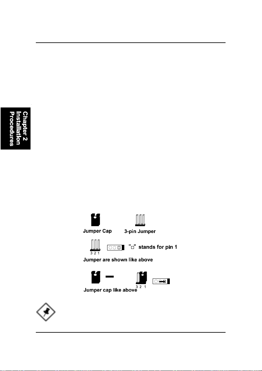
1). Set System Jumpers
Jumpers are used to select the operation modes for your system. Some jump-
ers on the board have three metal pins with each pin representing a different
function. A 1 is written besides pin 1 on jumpers with three pins. To set a
jumper, a black cap containing metal contacts is placed over the jumper pin/s
according to the required configuration. A jumper is said to be shorted when
the black cap has been placed on one or two of its pins. The types of jumpers
used in this manual are shown below:
NOTE: Users are not encouraged to change the jumper settings
not listed in this manual. Changing the jumper settings improperly
may adversely affect system performance.
3). CPU Fan Installation
This connector is linked to the CPU fan. When the system is in power saving mode, the
CPU fan will turn off; when it reverts back to full on mode, the fan will turn back on.
Without sufficient air circulation, the CPU may overheat resulting in damage
to both the CPU and the mainboard.
Damage may occur to the mainboard and/or the CPU fan if these pins are
used incorrectly. These are not jumpers, do not place jumper caps over these
pins.

2 - 5
Installation Procedures
2). Install Memory Modules
1. Locate the DIMM slots on the mainboard.
2. Install the DIMM straight down into the DIMM slot using both hands.
3. The clip on both ends of the DIMM slot will close up to hold the DIMM
in place when the DIMM reaches the slots bottom.
Clear CMOS: CLR_CMOS
The CMOS RAM is powered by the onboard button cell battery. To clear the
RTC data: (1) Turn off your computer. (2) Place the jumper cap onto the pinpair
2-3 to clear CMOS (3) Turn on your computer until CMOS checksum error
appears (4) Turn off your computer. (5) Place the jumper cap onto the pinpair
1-2 to Normal (6) Turn on your computer. (7) Hold down the Delete key when
boots. (8) Enter the BIOS Setup to re-enter user preferences.

2 - 6
FR33EMainboardManual
Press the clips with both hands to remove the DIMM.
3). Install the CPU
The mainboard has built-in Switching Voltage Regulator to support CPU Vcore
autodetection. That is, It has the ability to detect and recognize the CPU
voltage, clock, ratio and enables users to set up the CPU frequency from the
BIOS Setup Screen. Users can adjust the frequency through Frequency /
Voltage Control of the BIOS Setup Screen.

2 - 7
Installation Procedures
CAUTION:
1. The heatsink and fan you installed must be approved by CPU
|||||manufactories.
2. The mainboard must be placed on a solid place to avoid shaking
|||||while install the heatsink and fan on the board.
3. The heatsink must be contact with the CPU top tightly.
4. Never run the processor without the heatsink properly and firmly
attached. PERMANENT DAMAGE WILL RESULT!
To install the CPU, do the following:
1. Lift the lever on the side of the CPU socket.
2. Handle the chip by its edges and try not to touch any of the pins.
3. Place the CPU in the socket. The chip has two notches to correctly locate
the chip. Align two notches of the processor with the two triangular
marks on the socket. Do not force the chip. The CPU should slide easily
into the socket.
4. Swing the lever to the down position to lock the CPU in place.
5. Install the cooling fan with heatsink on top of the installed CPU.
6. Place the mainboard (with the CPU, its cooling fan, and heatsink) into the
system chassis and affix it with screws.
4). Install Expansion Cards
This section describes how to connect an expansion card to one of your
system expansion slots. Expansion cards are printed circuit boards that, when
connected to the mainboard, increase the capabilities of your system. For
example, expansion cards can provide video and sound capabilities. The
mainboard features one AMR, one ISA, and two PCI bus expansion slots.

2 - 8
FR33EMainboardManual
CAUTION: Make sure to unplug the power supply when adding or
removing expansion cards or other system components. Failure to
do so may cause severe damage to both the mainboard and
expansioncards.
Always observe static electricity precautions.
Please read Handling Precautions at the start of this manual.
To install an expansion card, follow the steps below:
1. Remove the computer chassis cover and select an empty expansion
slot.
2. Remove the corresponding slot cover from the computer chassis.
Unscrew the mounting screw that secures the slot cover and pull
the slot cover out from the computer chassis. Keep the slot cover
mounting screw nearby.
3. Holding the edge of the peripheral card, carefully align the edge
connector with the expansion slot.
4. Push the card firmly into the slot. Push down on one end of the
expansion card, then the other. Use this rocking motion until the add
on card is firmly seated inside the expansion slot.
2 - 9
Installation Procedures
5). Connect Devices
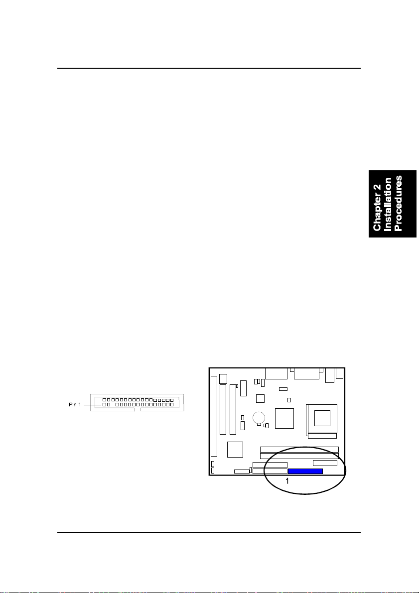
Floppy Diskette Drive Connector
This connector provides the connection with your floppy disk drive.
The red stripe of the ribbon cable must be the same side with the Pin 1.
5. Secure the board with the mounting screw removed in Step 2. Make
sure that the card has been placed evenly and completely into the
expansion slot.
6. Replace the computer system cover.
7. Setup the BIOS if necessary.
8. Install the necessary software drivers for the expansion card.
2 - 10
FR33EMainboardManual
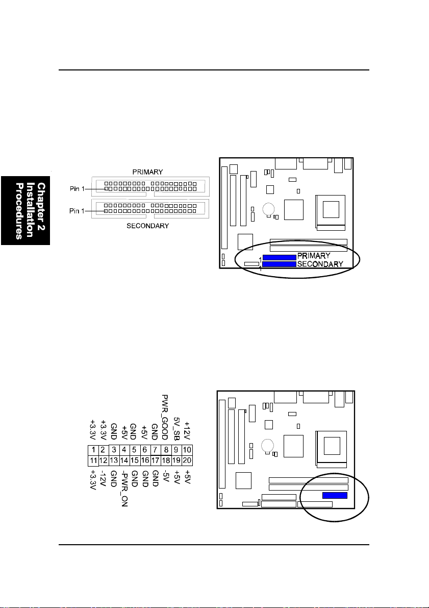
ATX Power Connector
This 20-pin male block connector is connected to the ATX power supply. The
plug from the power supply will only insert in one orientation because of the
different hole sizes. Find the proper orientation and push down firmly making
sure that the pins are aligned.
IDE Device Connectors
These two connectors are used for your IDE hard disk drives, CD drives, LS-
120|drives, or IDE ZIP drives. The red stripe of the ribbon cable must be the
same side with the Pin 1.
Table of contents
Other FIC Motherboard manuals


