ADF HD67059-232-B2 User manual
Industrial Electronic Devices
ADFweb.com S.r.l.
User Manual
M
-
Bus Slave / Modbus Master
-
Converter
Document code: MN67059_ENG Revision 2 000 Page 1 of 33
User Manual
Revision 2 000
English
M-Bus Slave / Modbus Master -
Converter
(Order Code: HD67059-232-B2, HD67059-485-B2)
For Website information:
www adfweb com?Product=HD67059
For Price information:
www adfweb com?Price=HD67059-232-B2
www adfweb com?Price=HD67059-485-B2
Benefits and Main Features:
Very easy to configure
Electrical isolation
Temperature range: -40°C/85°C (-40°F/185°F)
For others M-Bus products see also the following link:
Converter M-Bus Wireless to
www adfweb com?Product=HD67083 (Modbus TCP
Slave)
www adfweb com?Product=HD67084 (Ethernet)
Converter M-Bus to
www adfweb com?Product=HD67021 (RS 3 )
www adfweb com?Product=HD67022 (RS485)
Analyzer / Scanner /Sniffer M-Bus
www adfweb com?Product=HD67031
Isolator/Repeater M-Bus
www adfweb com?Product=HD67032M
Gateway M-Bus / Modbus TCP
www adfweb com?Product=HD67044
Gateway M-Bus / PROFIBUS
www adfweb com?Product=HD67053M
Gateway M-Bus Concentrator
www adfweb com?Product=HD67054M
Gateway M-Bus Slave / Modbus RTU master
www adfweb com?Product=HD67059M-232
Do you have an your customer protocol?
www adfweb com?Product=HD67003
Do you need to choose a device? do you want help?
www adfweb com?Cmd=helpme
User Manual

Industrial Electronic Devices
ADFweb.com S.r.l.
User Manual
M
-
Bus Slave / Modbus Master
-
Converter
Document code: MN67059_ENG Revision 2 000 Page 2 of 33
INDEX:
Page
INDEX 2
UPDATED DOCUMENTATION 2
REVISION LIST 2
WARNING 2
TRADEMARKS 2
SECURITY ALERT 3
EXAMPLE OF CONNECTION 4
CONNECTION SCHEME 5
CHARACTERISTICS 7
CONFIGURATION 7
POWER SUPPLY 8
FUNCTION MODES 9
LEDS 10
RS232 11
RS485 12
M-BUS 13
ETHERNET 13
USE OF COMPOSITOR SW67059 14
NEW CONFIGURATION / OPEN CONFIGURATION 15
SOFTWARE OPTIONS 16
SET COMMUNICATION 18
M-BUS 21
UPDATE DEVICE 27
MECHANICAL DIMENSIONS 30
ORDERING INFORMATIONS 31
ACCESSORIES 31
DISCLAIMER 32
OTHER REGULATIONS AND STANDARDS 32
WARRANTIES AND TECHNICAL SUPPORT 33
RETURN POLICY 33
UPDATED DOCUMENTATION:
Dear customer, we thank you for your attention and we remind you that
you need to check that the following document is:
Updated
Related to the product you own
To obtain the most recently updated document, note the “document code”
that appears at the top right-hand corner of each page of this document
With this “Document Code” go to web page www adfweb com/download/
and search for the corresponding code on the page Click on the proper
“Document Code” and download the updates
REVISION LIST:
WARNING:
ADFweb com reserves the right to change information in this manual about
our product without warning
ADFweb com is not responsible for any error this manual may contain
TRADEMARKS:
All trademarks mentioned in this document belong to their respective
owners
Revision
Date Author Chapter
Description
1 002 08/04/2011
Fl All Revision
1 010 05/10/2011
Fl All Software changed (v1 100)
1 011 18/02/2013
Nt All Added new chapters
2 000 15/12/2017
Ff All New hardware version

Industrial Electronic Devices
ADFweb.com S.r.l.
User Manual
M
-
Bus Slave / Modbus Master
-
Converter
Document code: MN67059_ENG Revision 2 000 Page 3 of 33
SECURITY ALERT:
G
ENERAL
I
NFORMATION
To ensure safe operation, the device must be operated according to the instructions in the manual When using the device, legal and
safety regulation are required for each individual application The same applies also when using accessories
I
NTENDED
U
SE
Machines and systems must be designed so the faulty conditions do not lead to a dangerous situation for the operator (i e
independent limit switches, mechanical interlocks, etc )
Q
UALIFIED
P
ERSONNEL
The device can be used only by qualified personnel, strictly in accordance with the specifications
Qualified personnel are persons who are familiar with the installation, assembly, commissioning and operation of this equipment and
who have appropriate qualifications for their job
R
ESIDUAL
R
ISKS
The device is state-of-the-art and is safe The instruments can represent a potential hazard if they are inappropriately installed and
operated by untrained personnel These instructions refer to residual risks with the following symbol:
This symbol indicates that non-observance of the safety instructions is a danger for people that could lead to serious injury or
death and / or the possibility of damage
CE
CONFORMITY
The declaration is made by our company You can send an email to support@adfweb com or give us a call if you need it
Industrial Electronic Devices
ADFweb.com S.r.l.
User Manual
M
-
Bus Slave / Modbus Master
-
Converter
Document code: MN67059_ENG Revision 2 000 Page 4 of 33
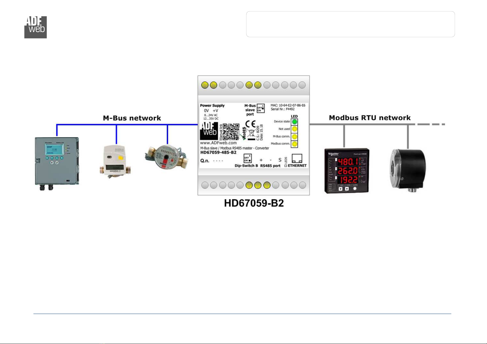
EXAMPLE OF CONNECTION:
Industrial Electronic Devices
ADFweb.com S.r.l.
User Manual
M
-
Bus Slave / Modbus Master
-
Converter
Document code: MN67059_ENG Revision 2 000 Page 5 of 33
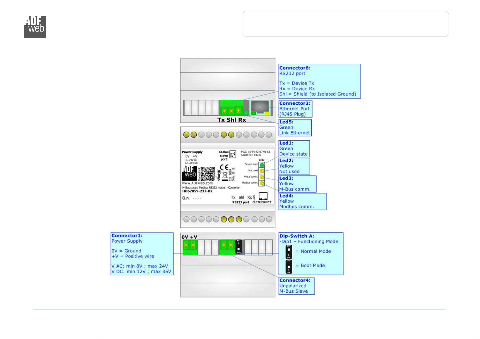
CONNECTION SCHEME:
Figure
1a
: Connection scheme for HD670
5
-
232
-
B2
Industrial Electronic Devices
ADFweb.com S.r.l.
User Manual
M
-
Bus Slave / Modbus Master
-
Converter
Document code: MN67059_ENG Revision 2 000 Page 6 of 33
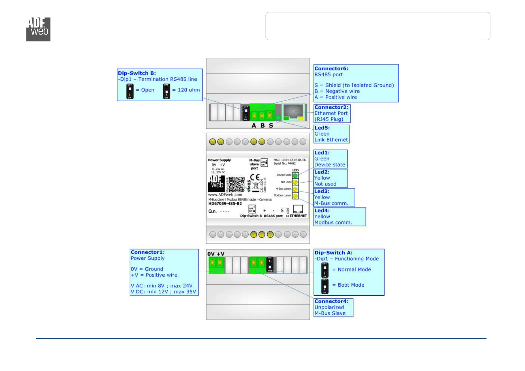
Figure 1b: Connection scheme for HD6705 -485-B2

Industrial Electronic Devices
ADFweb.com S.r.l.
User Manual
M
-
Bus Slave / Modbus Master
-
Converter
Document code: MN67059_ENG Revision 2 000 Page 7 of 33
CHARACTERISTICS:
The HD67059 is a M-Bus slave to Modbus master converter
It allows the following characteristics:
Electrical isolation between RS232/RS485 - M-Bus – Power Supply;
Baud Rate and Parity changeable with software;
Mountable on 35mm Rail DIN;
Wide power supply input range: 8…24V AC or 12…35V DC;
Wide temperature range: -40°C / 85°C [-40°F / +185°F]
CONFIGURATION:
You need Compositor SW67059 software on your PC in order to perform the following:
Define the parameter of Modbus and M-Bus line;
Define the map between M-Bus and Modbus sides;
Update the device
Industrial Electronic Devices
ADFweb.com S.r.l.
User Manual
M
-
Bus Slave / Modbus Master
-
Converter
Document code: MN67059_ENG Revision 2 000 Page 8 of 33
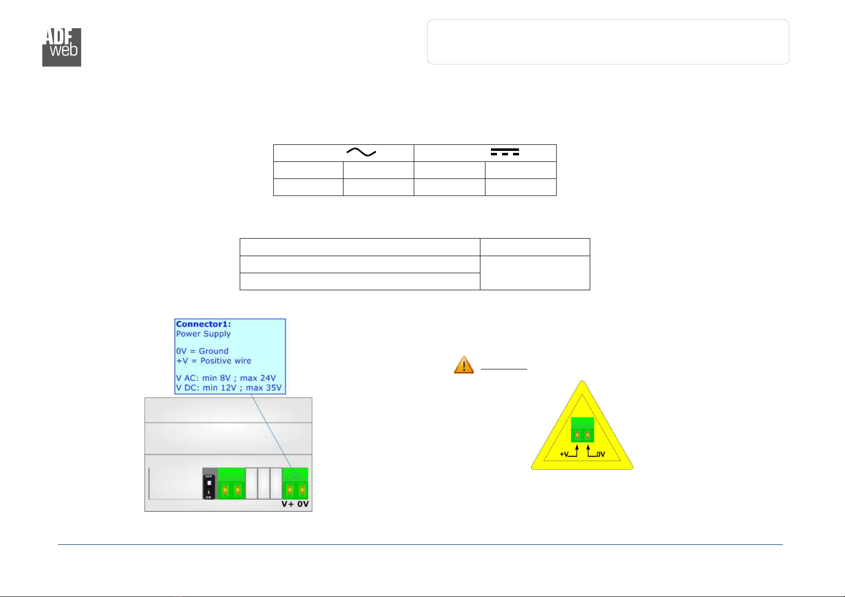
POWER SUPPLY:
The devices can be powered at 8…24V AC and 12…35V DC The consumption depends to the code of the device For more details see the two
tables below
VAC
VDC
Vmin Vmax Vmin Vmax
8V 4V 1 V 35V
Consumption at 24V DC:
Device [W/VA]
HD67059-232-B2 4
HD67059-485-B2
HD67059
Warning: Not reverse the polarity power
Industrial Electronic Devices
ADFweb.com S.r.l.
User Manual
M
-
Bus Slave / Modbus Master
-
Converter
Document code: MN67059_ENG Revision 2 000 Page 9 of 33
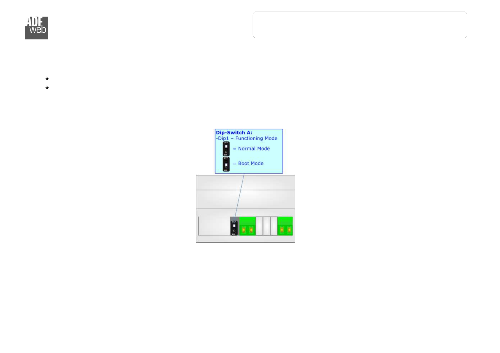
FUNCTION MODES:
The device has got two functions mode depending of the position of Dip1 of ‘Dip-Switch A’ of HD67059-xxx-B2:
The first, with Dip1 of ‘Dip-Switch A’ at OFF position, is used for the normal working of the device
The second, with Dip1 of ‘Dip-Switch A’ at ON position, is used for uploading the Project and/or Firmware
For the operations to follow for the updating, see ‘UPDATE DEVICE’ section
According to the functioning mode, the LEDs will have specifics functions, see ‘LEDS’ section
Industrial Electronic Devices
ADFweb.com S.r.l.
User Manual
M
-
Bus Slave / Modbus Master
-
Converter
Document code: MN67059_ENG Revision 2 000 Page 10 of 33
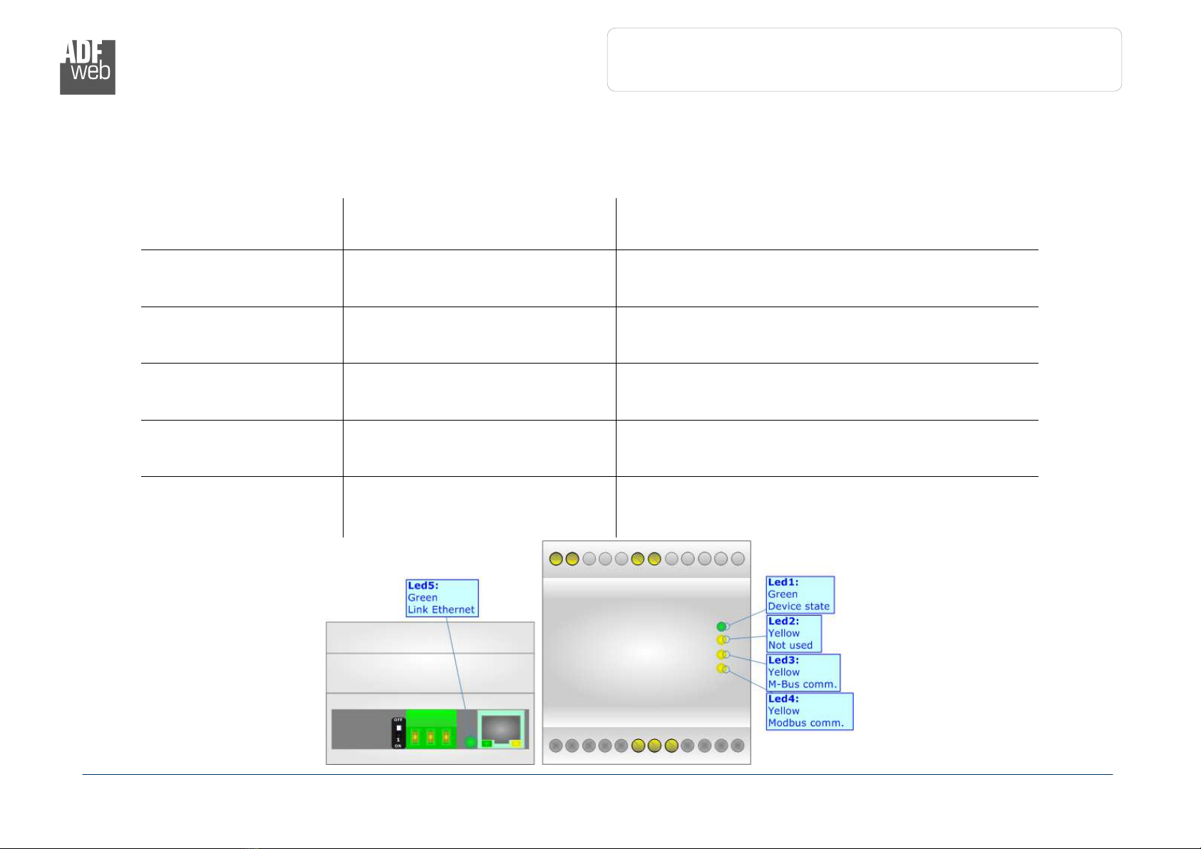
LEDS:
The device has got five LEDs that are used to give information of the functioning status
The various meanings of the LEDs are described in the table below
LED Normal Mode Boot Mode
1: Device state (green) Blinks slowly (~1Hz)
Blinks quickly: Boot state
Blinks very slowly (~0.5Hz): update in progress
2: Not used (yellow) OFF
Blinks quickly: Boot state
Blinks very slowly (~0.5Hz): update in progress
3: M-Bus Comm (yellow) Blinks when a M-Bus request is
received
Blinks quickly: Boot state
Blinks very slowly (~0.5Hz): update in progress
4: Modbus comm
(yellow)
Blinks when a Modbus response is
received
Blinks quickly: Boot state
Blinks very slowly (~0.5Hz): update in progress
5: Ethernet Link (green) ON: Ethernet cable connected
OFF: Ethernet cable disconnected
ON: Ethernet cable connected
OFF: Ethernet cable disconnected

Industrial Electronic Devices
ADFweb.com S.r.l.
User Manual
M
-
Bus Slave / Modbus Master
-
Converter
Document code: MN67059_ENG Revision 2 000 Page 11 of 33
RS 3 :
The connection from RS232 socket to a serial port (example one from a personal computer) must be made with a Null Modem cable (a serial
cable where the pins 2 and 3 are crossed) It is recommended that the RS232 cable not exceed 15 meters
Industrial Electronic Devices
ADFweb.com S.r.l.
User Manual
M
-
Bus Slave / Modbus Master
-
Converter
Document code: MN67059_ENG Revision 2 000 Page 12 of 33
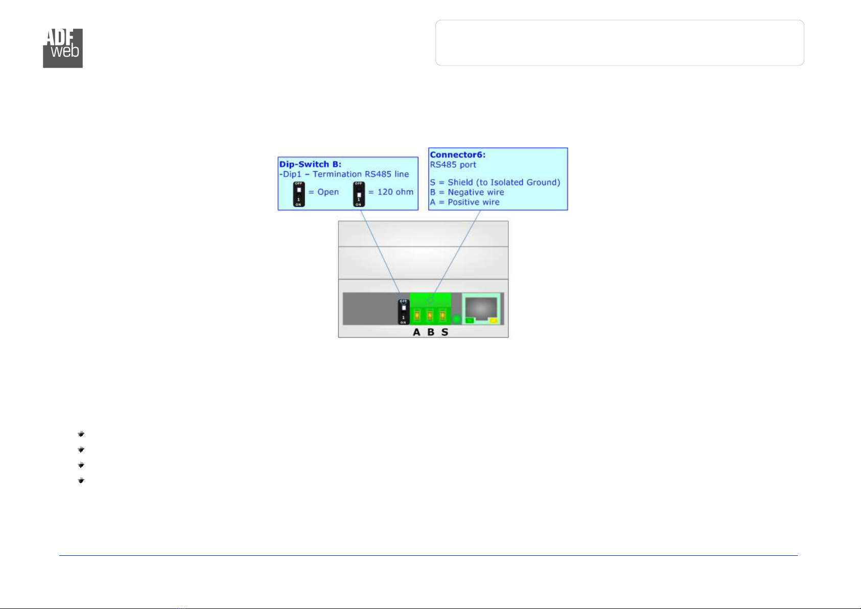
RS485:
To terminate the RS485 line with a 120Ω resistor, it is necessary to put dip 1 ON, like in figure
The maximum length of the cable should be 1200m (4000 feet)
Here some codes of cables:
Belden: p/n 8132 - 2x 28AWG stranded twisted pairs conductor + foil shield + braid shield;
Belden p/n 82842 - 2x 24AWG stranded twisted pairs conductor + foil shield + braid shield;
Tasker: p/n C521 - 1x 24AWG twisted pair conductor + foil shield + braid shield;
Tasker: p/n C522 - 2x 24AWG twisted pairs conductor + foil shield + braid shield

Industrial Electronic Devices
ADFweb.com S.r.l.
User Manual
M
-
Bus Slave / Modbus Master
-
Converter
Document code: MN67059_ENG Revision 2 000 Page 13 of 33
M-BUS:
The M-Bus is a unpolarized bus
A two wire standard telephone cable (JYStY N*2*0 8 mm) is used as the transmission medium for the M-
Bus
ETHERNET:
The Ethernet connection must be made using Connector3 with at least a Category 5E cable The
maximum length of the cable should not exceed 100m The cable has to conform to the T568 norms
relative to connections in cat 5 up to 100 Mbps To connect the device to an Hub/Switch is recommended
the use of a straight cable, to connect the device to a PC/PLC/other is recommended the use of a cross
cable
Industrial Electronic Devices
ADFweb.com S.r.l.
User Manual
M
-
Bus Slave / Modbus Master
-
Converter
Document code: MN67059_ENG Revision 2 000 Page 14 of 33
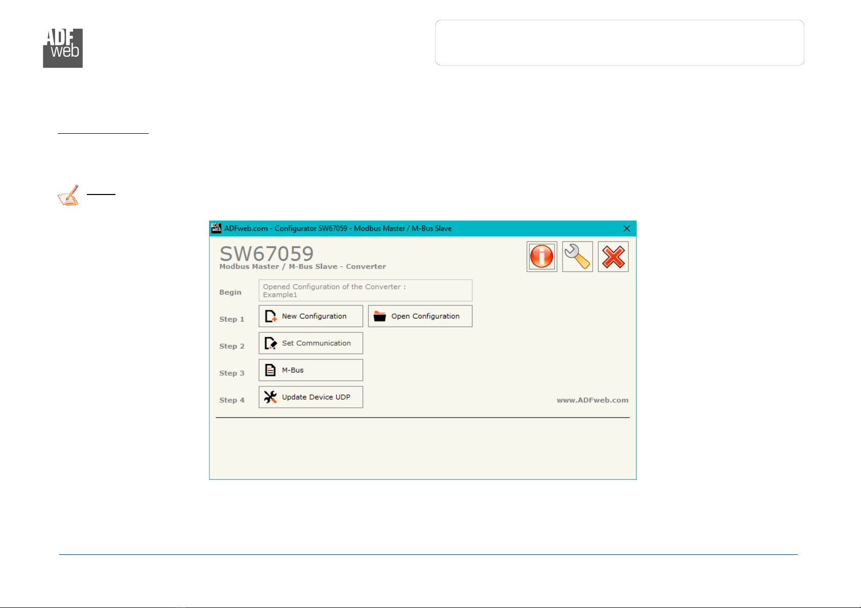
USE OF COMPOSITOR SW67059:
To configure the Converter, use the available software that runs with Windows called SW67059 It is downloadable from the site
www adfweb com and its operation is described in this document (this manual is referenced to the last version of the software present on the
web site) The software works with MSWindows (XP, Vista, Seven, 8, 10; 32/64bit)
When launching the SW67059, the window below appears (Fig 2)
Note:
It is necessary to have installed Net Framework 4
Figure 2:
Main window for SW6705
Industrial Electronic Devices
ADFweb.com S.r.l.
User Manual
M
-
Bus Slave / Modbus Master
-
Converter
Document code: MN67059_ENG Revision 2 000 Page 15 of 33
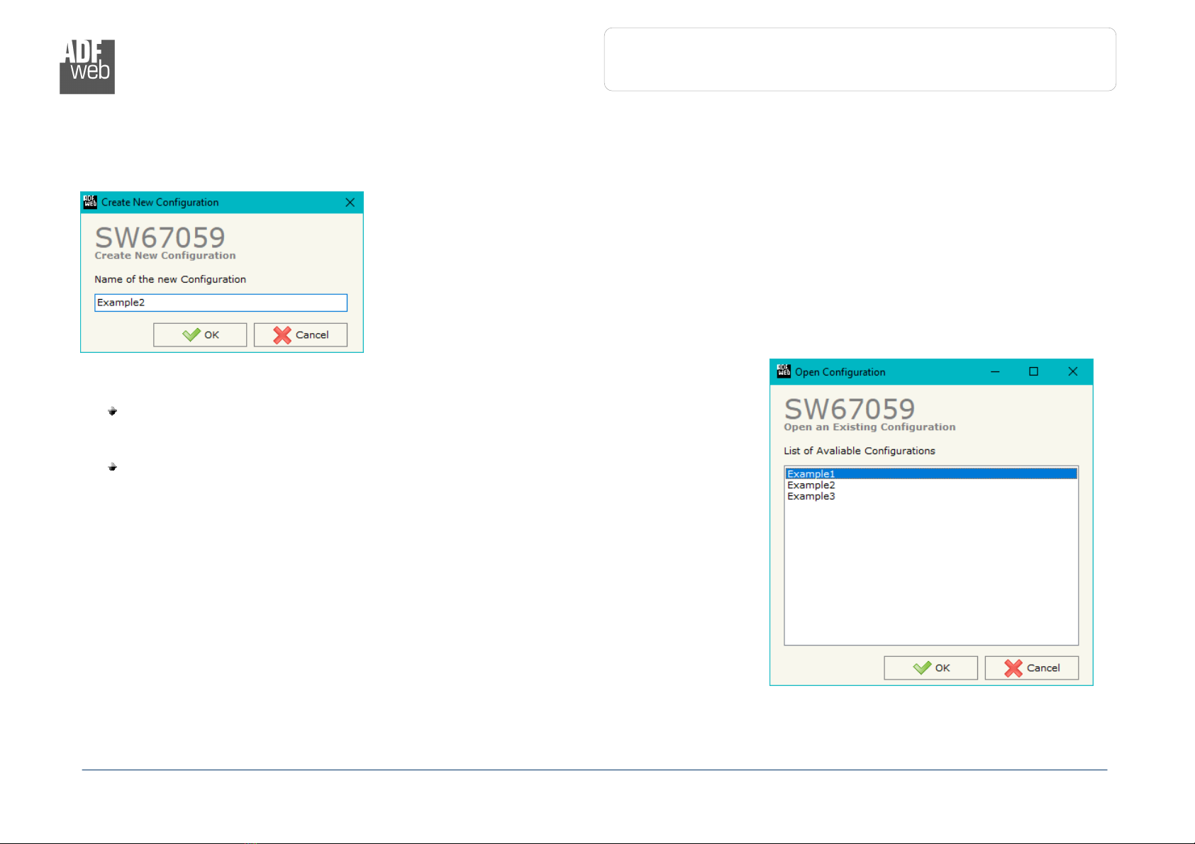
NEW CONFIGURATION / OPEN CONFIGURATION:
The “New Configuration” button creates the folder which contains the entire device’s configuration
A device’s configuration can also be imported or exported:
To clone the configurations of a programmable “M-Bus Slave / Modbus Master -
Converter” in order to configure another device in the same manner, it is necessary to
maintain the folder and all its contents;
To clone a project in order to obtain a different version of the project, it is sufficient to
duplicate the project folder with another name and open the new folder with the
button “Open Configuration”
Industrial Electronic Devices
ADFweb.com S.r.l.
User Manual
M
-
Bus Slave / Modbus Master
-
Converter
Document code: MN67059_ENG Revision 2 000 Page 16 of 33
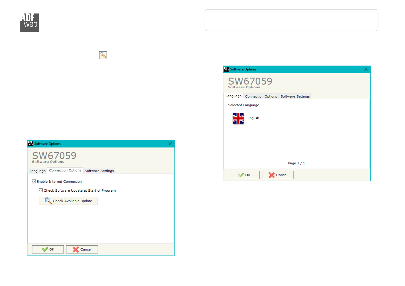
SOFTWARE OPTIONS:
By pressing the “Settings” ( ) button there is the possibility to change the language of the software and check the updatings for the
compositor
In the section “Language” it is possible to change the language of the
software
In the section “Connection Options”, it is possible to check if there are some
updatings of the software compositor in ADFweb com website
Checking the option “Check Software Update at Start of Program”, the
SW67059 check automatically if there are updatings when it is launched
Industrial Electronic Devices
ADFweb.com S.r.l.
User Manual
M
-
Bus Slave / Modbus Master
-
Converter
Document code: MN67059_ENG Revision 2 000 Page 17 of 33
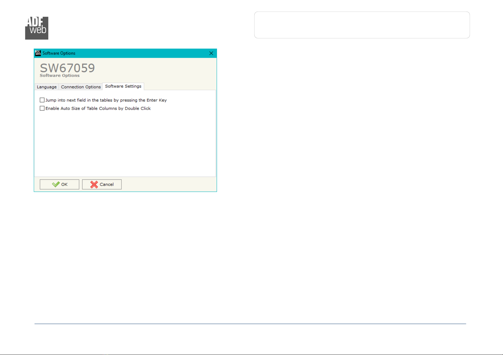
In the section “Software Settings”, it is possible to enable/disable some
keyboard’s commands for an easier navigation inside the tables contained in
the different sections of the software

Industrial Electronic Devices
ADFweb.com S.r.l.
User Manual
M
-
Bus Slave / Modbus Master
-
Converter
Document code: MN67059_ENG Revision 2 000 Page 18 of 33
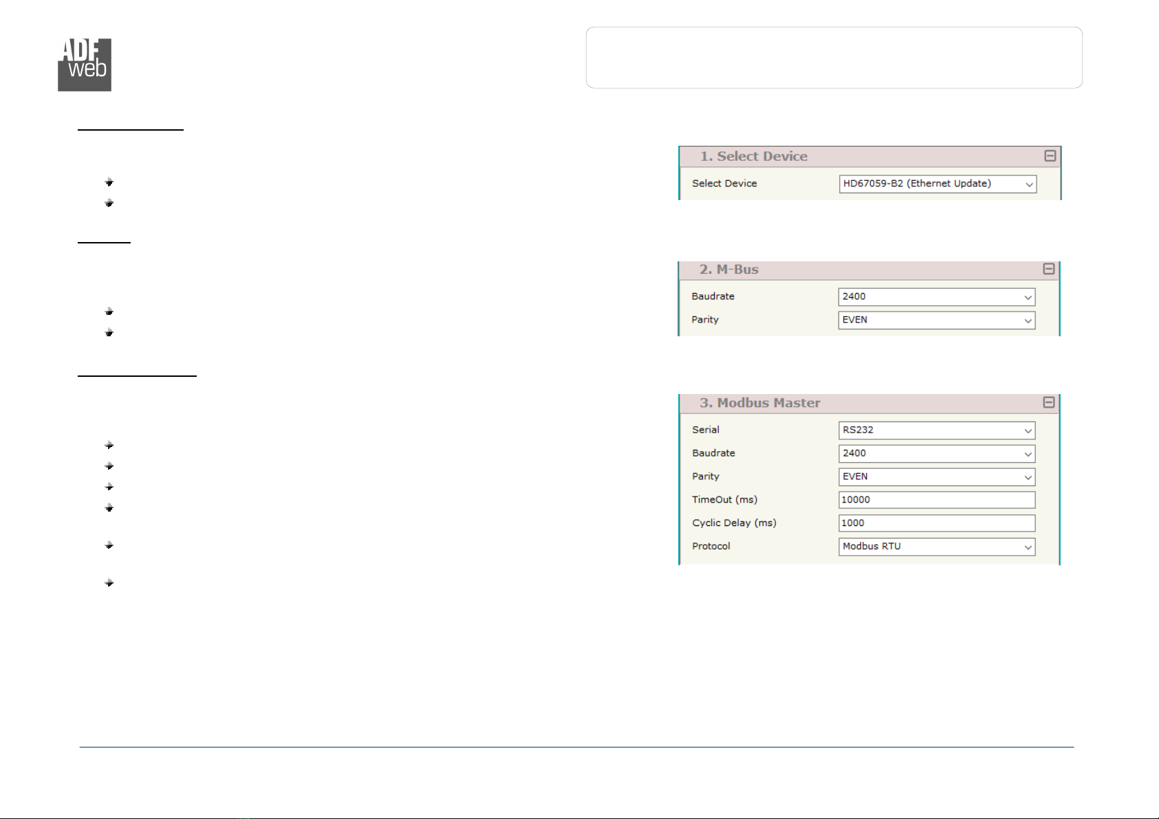
SET COMMUNICATION:
By Pressing the “Set Communication” button from the main window for SW67059
(Fig 2) the window “Set Communication” appears (Fig 3)
The window is divided in different sections in order to define the different
parameters of the converter:
Select Device
M-Bus
Ethernet
Modbus Master
Figure 3a: “Set Communication” window
Industrial Electronic Devices
ADFweb.com S.r.l.
User Manual
M
-
Bus Slave / Modbus Master
-
Converter
Document code: MN67059_ENG Revision 2 000 Page 19 of 33
Figure 3b: “Set Communication
Select Device” window
Figure 3c: “Set Communication
M
-
Bus” window
Figure 3d: “Set Communication
Modbus Master”
window
S
ELECT
D
EVICE
:
This section is used to define hardware type used:
HD67059M (Serial Update): old hardware version (6M box)
HD67059-B (Serial Update): new hardware version (4M box)
M-B
US
:
This section is used to define the main parameters of M-Bus line The means of the
fields are:
In the field “Baudrate” the data rate of the M-Bus line is defined;
In the field “Parity” the parity of the M-Bus line is defined;
M
ODBUS
M
ASTER
:
This section is used to define the main parameters of Modbus line The means of the
fields are:
In the field “Serial” the serial port to use is defined (RS232 or RS485);
In the field “Baudrate” the baudrate for the serial line is defined;
In the field “Parity” the parity of the serial line is defined;
In the field “TimeOut (ms)” the maximum time that the converter attends
for the answer from the Slave interrogated is defined;
In the field “Cyclic Delay (ms)” the delay (idle time) between two Modbus
requests is defined;
In the field “Protocol” the protocol used on serial side is defined
Industrial Electronic Devices
ADFweb.com S.r.l.
User Manual
M
-
Bus Slave / Modbus Master
-
Converter
Document code: MN67059_ENG Revision 2 000 Page 20 of 33
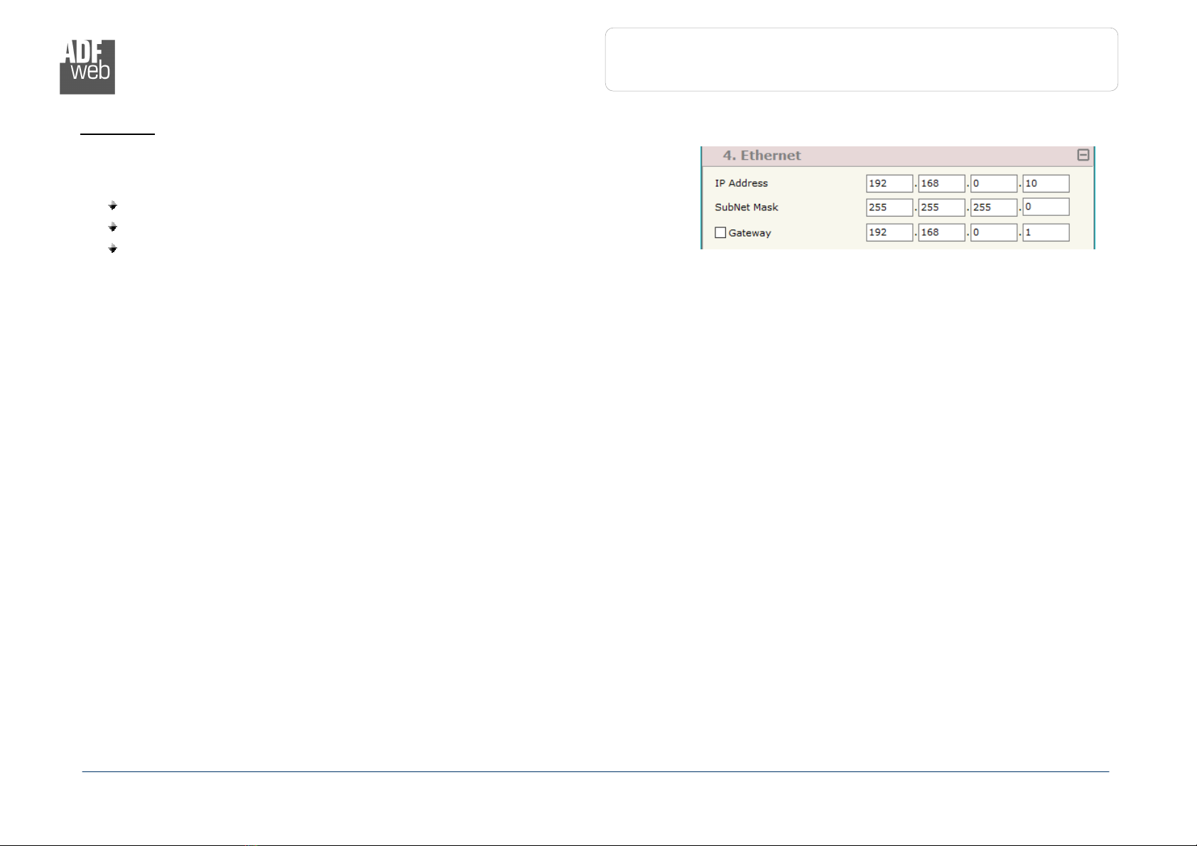
Figure 3e: “Set Communication
Ethernet”
window
E
THERNET
:
This section is used to define the general parameters of Ethernet The means of the
fields are:
In the field “Ip Address” the IP address of the converter is defined;
In the field “SubNet Mask” the Subnet Mask of the converter is defined;
In the field “Gateway” the default gateway of the net is defined This
feature can be enabled or disabled pressing the Check Box field This feature
is used for going out of the net;
This manual suits for next models
1
Table of contents
Popular Media Converter manuals by other brands


Encore
Encore 2040MO instruction manual

3One data
3One data IMC101B Series Quick installation guide

Bosch
Bosch VIDEOJET connect 7000 installation manual

PCB Piezotronics
PCB Piezotronics 422E53 Installation and operating manual

pico Technology
pico Technology ADC-10 installation guide

Axel
Axel EX-2200 user manual


