ADF 100 DUO User manual

Owner’s Manual
ADF LINEA 100 DUO
Inbuilt Appliance
Supplied by:
Castworks Pty Ltd
12 Fiveways Boulevard
Keysborough VIC 3173
TESTED IN ACCORDANCE WITH AS/NZS 4012:2014 & AS/NZS 4013:2014
Please read this manual thoroughly before installing and starting your free-standing appliance.
Keep these instructions for future reference
V18062018

2
Index
1. Introduction 03
2. Appliance Layout 05
3. Technical Specifications 06
4. Installation Instructions 09
A. Installation into a Skamol Enclosure Board Construction 09
B. Installation into a Zero Clearance Box and Timber Framing 14
C. Ducting - Convection Air Transfer Ducting 15
D. Decorative Frame Trim 17
5. Flue Installation and Outlet 18
6. Fan 20
7. Installing the bricks and baffles 22
8. Instructions for use 23
9. Maintenance and cleaning 24
10. Troubleshooting 26
11. Warranty 27
12. Data Label 29
3
1. Introduction
Congratulations on your purchase of your new ADF woodfire appliance!
Years of extensive research and dedication to innovation and quality, since 1976, has resulted in these
beautifully designed European appliances, constructed to strict Portuguese and European legislation, and
tested and Certified to the Australian Emissions, Efficiency and Safety standard requirements
guaranteeing excellent performance.
Please read this manual fully to ensure safe and efficient use of your heater and to comply with the
warranty guidelines.
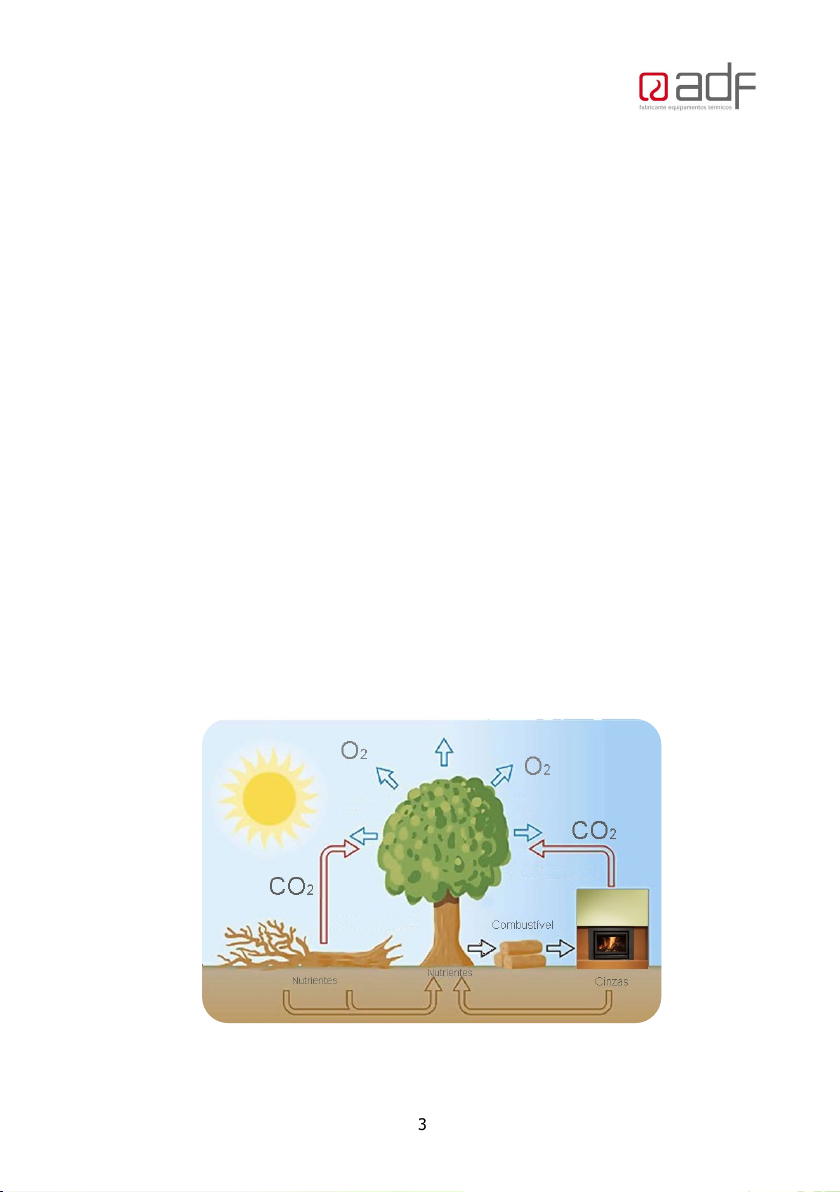
Solid Fuel – Ecological Energy
Through photosynthesis, plants capture energy from the sun and transform it into chemical energy. The
trapped energy, e.g., in the form of wood, pellets, coal are called biomass fuels and can be converted
into various forms: electricity, fuel or heat. Biomass burning causes the release of carbon dioxide into
the atmosphere, but since this compound had previously been absorbed by the plants that originated
the fuel, the CO2 emissions balance is zero, not contributing to the greenhouse effect on the planet.
Firewood is the most environmentally friendly way of producing heat in your home, as it is a fully
renewable resource. The amount of CO2 that is released during the combustion of firewood is not higher
than the amount that would be released from its natural decomposition. Wood ash is a mineral fertilizer
easily absorbed by the environment in a totally ecological way.
4
Firewood – Use
Choosing your wood
All wood types have a different calorific value. You should choose only well-seasoned hard woods.Do
not use logs that are too large.Split round logs so they cannot roll and cause a hazard.
Drying your wood
Whichever firewood is chosen; it must be very dry and seasoned. Unseasoned or green firewood does
not heat as much, because a large part of the energy is consumed in the evaporation of the water and
creosote contained in the wood, which is highly corrosive and will damage the appliance and
consequently it could void your Warranty. In addition, moist firewood produces a large amount of
smoke and little flame, which will foul the appliance, the glass, and the chimney. When raining the
stored wood should be covered and well ventilated. Generally, green wood should be left to “season”
for two years.
Wood to Avoid
Softwoods and low-density wood: This kind of firewood release a lot of heat but burn too quickly and
projects embers and resin that foul the chimney and the interior of your woodstove.These should be
used as Kindling only, for starting your fire.
Do not use:
Wood with varnish, exotic wood, treated/painted timber, agglomerates that can produce toxic fumes
which will damage the appliance. Do not use driftwood or coastal wood with high salt content, it will
quickly damage the heater.
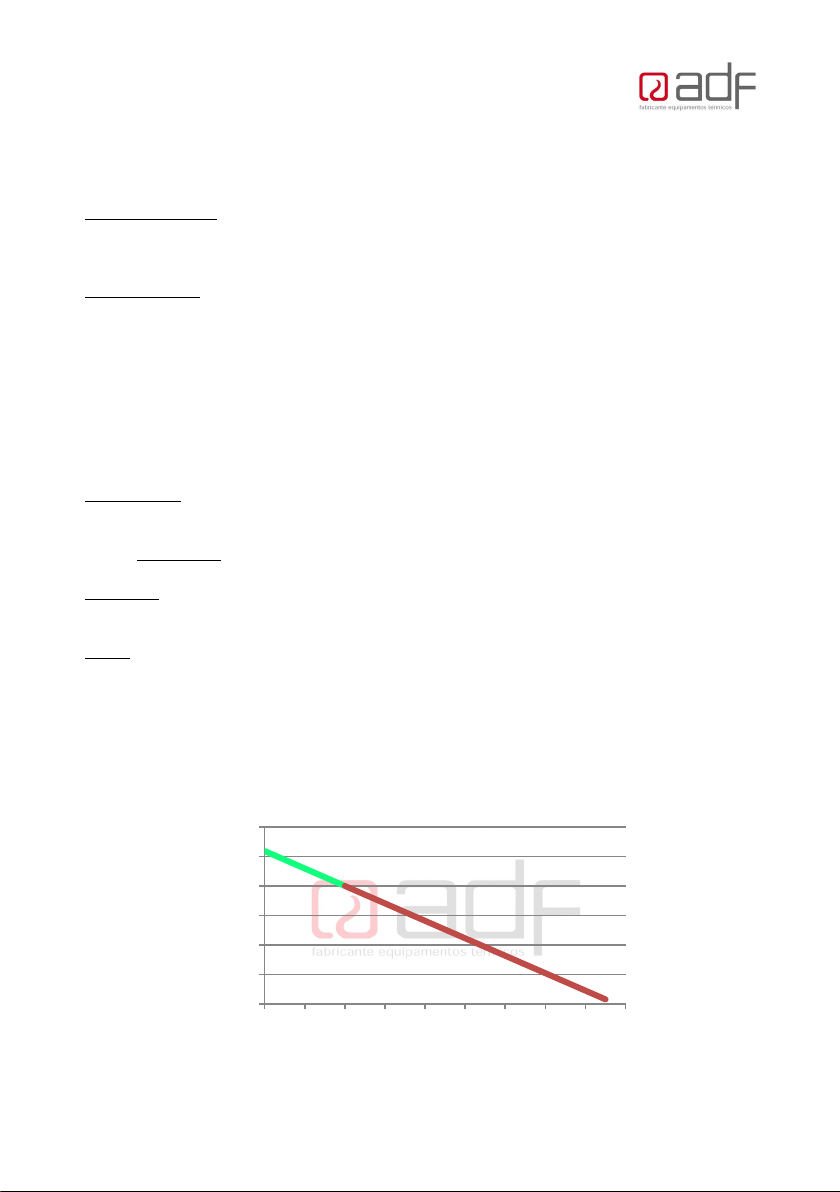
All ADF appliances are designed to burn firewood and firewood only, with less than 20% moisture
content. The use of unseasoned firewood or firewood with moisture or other types of fuel not
recommended will void the warranty.See below, the drier the wood the better heat you get out of it.
0.0
1.0
2.0
3.0
4.0
5.0
6.0
010 20 30 40 50 60 70 80 90
(kWh/kg)
Moisture (%)
Moisture Vs Energy released by firewood

5
2-Appliance Layout
Note: single sided unit shown.
Pos. Designation
1 Door lever, Tool supplied for Door and Air Control
2
Combustion Air control (Use tool):
Open (+) slide to the right
Close (-) slide to the left
3 Vermiculite brick lining
4 Primary convection outlet – comes out each side above both doors.
5 Secondary convection outlet (hot air distribution for ducting) Inbuilt only
6 Smoke Outlet – Flue collar 200mm (or 8” Crimped)
7 Convection inlet
Important:
oPlease read this manual thoroughly before installing and starting yourfree-standing appliance.
oInstallation must be carried out bya licenced and certified installer.
oKeep these instructions for future reference
When Lighting the fire for the first time - use only a
small kindling fire with a minimal amount of wood,
to remove moisture from the brick linings. Then
repeat the process for a longer duration to cure the
paint, without over firing - paint peeling. See full
warnings on page 21.

6
3- Technical Specification
Specifications
TESTED IN ACCORDANCE WITH
AS/NZS 4012:2014 & AS/NZS 4013:2014
Burning Harwood
Unit
ADF
DUO
100
Maximum Avearge Heat Output kW 18.9
Maximum Peak Heat Output kW 20.4
Overall Average Efficiency % 60
Particulate Emission Factor g/kg 1.1
Maximum firewood load kg 10
Minimum clearance distances from combustible materials mm
See page
11.
Flue Diameter mm 200
Recommended Fuel
Burn only Harwood
Moisture ≤ 20%
Electrical Specification – Note optional Fan requires
specific bench requirements and a wall mount control
W
36
V
220-240
Hz
50/60
Fan Settings
Variable speed from 2 to 8
Model
Dimensions (mm)
Width Depth Height Weight
ADF100 DUO 100 Linea (NMV-B) Freestanding
1010
550
565
220kg

7
WARNINGS:
A wood burning heater is, by its nature, an appliance that operates at high temperatures, so it is
necessary to take into account potential risk factors that should be avoided at all costs. Children must
be kept away from any combustion appliance and supervised in the room at all times.
Installation must be carried out by a licenced and certified installer.
The installation must meet the requirements of the manufacturers instructions, AS2918 and the Building
Code of Australia.
The appliance must be installed in such a way as to allow easy maintenance.
Incorrect installation may cause serious damage to the equipment and the safety of people and property.
Before installing your appliance, please ensure the following:
oThe appliance must be installed on a heat resistant surface to 600°C.
oThe floor must be structurally sound, to support the installation weight.
oThe compartment below the heater should not be used to store combustible materials (NM-RS
models).
oReplacement outside air must be supplied to the room with the heater, a minimum equivalent to
half the cross-sectional area of the flue, ie 160cm2 free air.
oFollow the clearances to combustible materials as shown on page 10. Or follow the Zero Clearance
box install.
oYour appliance must be non-permanently installed and easily accessible to ensure general
maintenance (chimney and equipment).
oThe equipment must not be cemented in its enclosure under any circumstances.
Keep these instructions for future reference
WARNINGS:
oREFER TO COMPLIANCE LABEL – DISREGARD ANY CONTRADICTORY FUEL TYPE INFORMATION IN
INSTRUCTION MANUAL
oWARNING: THE APPLIANCE & FLUE SYSTEM SHALL BE INSTALLED IN ACCORDANCE WITH AS/NZS
2918:2001 AND THE APPROPRIATE REQUIREMENTS OF THE RELEVANT BUILDING CODE OR CODES.
oWARNING: APPLIANCES INSTALLED IN ACCORDANCE WITH THIS STANDARD SHALL COMPLY WITH
THE REQUIREMENTS OF AS/NZS 4013:2014 WHERE REQUIRED BY THE REGULATORY AUTHORITY,
I.E. THE APPLIANCE SHALL BE IDENTIFIABLE BY A COMPLIANCE PLATE WITH THE MARKING “TESTED
TO AS/NZS 4013:2014”.
oANY MODIFICATION OF THE APPLIANCE THAT HAS NOT BEEN APPROVED IN WRITING BY THE
TESTING AUTHORITY IS CONSIDERED TO BE IN BREACH OF THE APPROVAL GRANTED FOR
COMPLIANCE WITH AS/NZS 4013:2014.

8
WARNINGS:
oCAUTION: MIXING OF APPLIANCE OR FLUE SYSTEM COMPONENTS FROM DIFFERENT SOURCES
OR MODIFYING THE DIMENSIONAL SPECIFICATION OF COMPONENETS MAY RESULT IN
HAZARDOUS CONDITIONS. WHERE SUCH ACTION IS CONSIDERED, THE MANUFACTURER SHOULD
BE CONSULTED INTHE FIRST INSTANCE.
oCAUTION: CRACKED AND BROKEN COMPONENTS, e.g., GLASS PANELS OR CERAMIC TILES,
MAY RENDER THE INSTALLATION UNSAFE.
oWARNING: ANY MODIFICATION OFTHE APPLICANCE THAT HAS NOT BEEN APPROVED IN
WRITING BY THE TESTING AUTHORITY IS CONSIDERED AS BREACHING AS/NZS 4013.
oWARNING: DONOT USE FLAMMABLE LIQUIDS ORAEROSOLS TOSTART ORREKINDLE THE FIRE.
oWARNING: DONOT USE FLAMMABLE LIQUIDS OR AEROSOLS IN THE VICINITY OFTHIS
APPLIANCE WHEN ITIS OPERATING.
oWARNING: DO NOT STORE FUEL WITHIN THE HEATER INSTALLATION CLEARANCES.
oWARNING: WHEN OPERATING THIS APPLIANCE AS AN OPEN FIRE USE A FIRE SCREEN.
oWARNING: OPEN AIR CONTROL (AND DAMPER WHEN FITTED) BEFORE OPENING FIRING DOOR.
oCAUTION: THIS APPLIANCE SHOULD NOT BE OPERATED WITH A CRACKED GLASS.
oTHIS APPLIANCE SHOULD BEMAINTAINED AND OPERATED AT ALL TIMES IN ACCORDANCE
WITH THESE INSTRUCTIONS.
oTHE USE OF SOME TYPES OF PRESERVATIVE-TREATED WOOD AS AFUEL CAN BE HAZARDOUS.
oTHE APPLIANCE OR FLUE SYSTEM SHOULD NOT BEMODIFIED IN ANY WAY WITHOUT THE
WRITTEN APPROVAL OF THE MANUFACTURER.
oBURN ONLY HARDWOOD
oPrior to installation check with your state and local authorities regarding any specific regulations that
may apply.
9
4-Installation
Keep these instructions for future reference
All local regulations, including those referring to national standards, must be observed
when installing the appliance.
NOTE: If the heater is supplied with base feet, these are to be removed. Remove the door to avoid
breakage, lay heater on its back, and undo the bolts fixing the feet. Feet are included for transit when
fan installed. If feet are required, ie including fan and using an existing hearth – contact your supplier if
required.
Replacement room air from outside equivalent to 314cm2 must be supplied into the room.
The heater must have its own dedicated flue. The active flue must be 8” for the entire length of the
flue, and always less than 45 degrees from the vertical.
The Flue terminal must meet the minimum height and external clearances for the flue, according to
AS/NZ 2918:2001, see the diagram shown below on page 12.
The ADF DUO Linea 100 was tested with a 200mm (8”) triple skin flue kit in a manner confirming to joint
Australia/New Zealand Standard 2918:2001.
A. INSTALLATION INTO A SKAMOL ENCLOSURE BOARD
CONSTRUCTION
The floor must be structurally sound.
The Hearth must have a heat resistant surface to 600°C, with an insulating thickness of non-
combustible material equivalent to 24mm of cement sheet with thermal resistivity of 0.1m².K/W for
6mm. eg Bellis Board or fibre cement sheet equivalent.
The base of the unit is raised 350mm from the floor protector for the following clearances to apply.
AS2918 default clearances apply for installations directly on the floor (75mm concrete slab suspended
with 25mm air gap below – see AS/NZS2918 3.3.3)
The appliance must be placed on a box 1000mm wide x 400mm high x 470mm deep made from 50mm
Skamol.
A minimum 300mm deep x 1240mm wide x 6mm thick floor protector (Bellis Board or similar cement
sheet) should be used in front and behind the appliance base when installing the appliance (see joint
AS/NZS 2918:2001 3.3.2). The floor protector must extend 300mm in front of both appliance fuel loading
doors and be placed centrally in the 1240mm width. The Thermal conductivity of the floor protector is
0.1m².K/W for 9mm thick sheets.
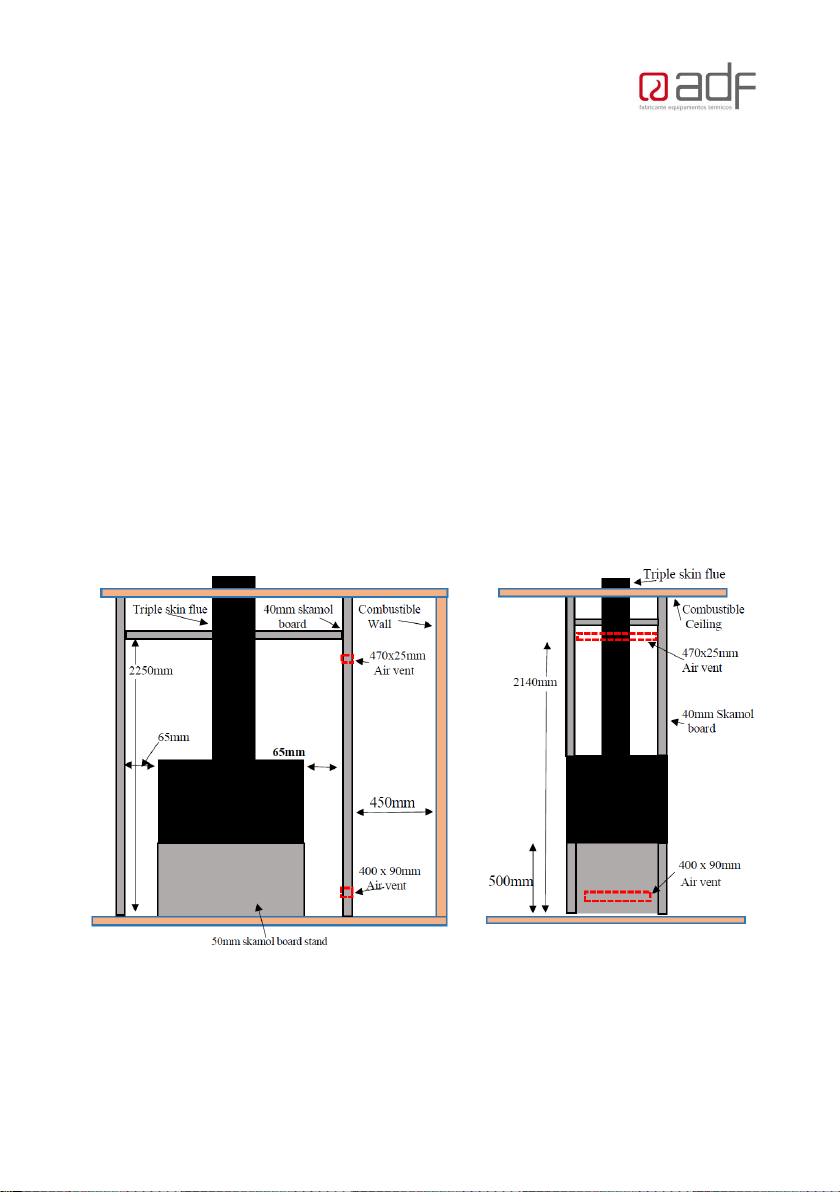
The Enclosure must be made from a minimum of 40mm thick, on all sides. There must be a minimum of
65mm side clearance between the heater and the skamol board. See dimensions below.
10
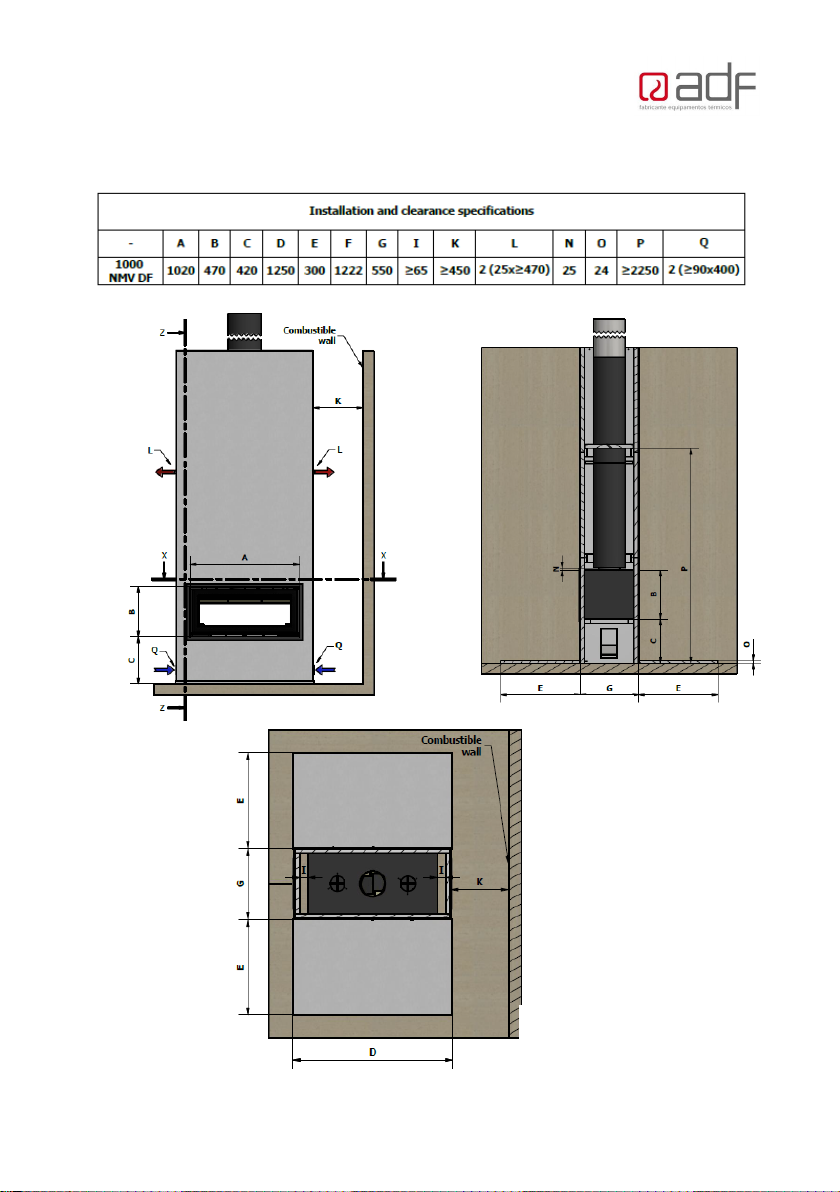
The appliance and flue were tested at the following clearances:
The side clearance to combustible walls or cabinetry from the Skamol enclosure wall, is 450mm from
the vent outlets.
Aminimum of two air vents must be installed. The top air vent must be 470mm long x 25mm high and
must not be closer than 235mm to the ceiling. The bottom air vent must be a minimum, 400mm long x
90mm high, and must be 60mm from the floor of the enclosure. Combustible material must be a
minimum of 450mm from the side vents. All enclosure joints must be sealed correctly to ensure they do
not allow heat to escape from enclosure.
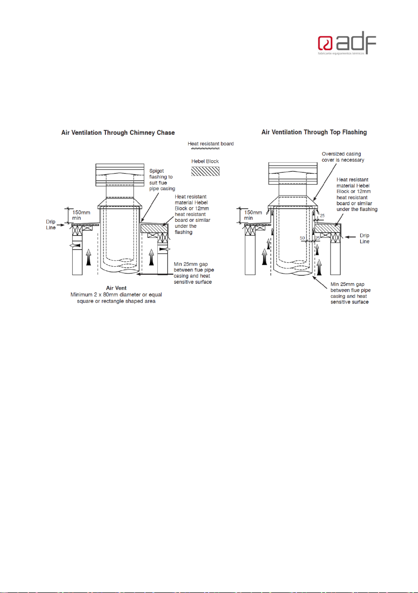
The combustible ceiling above the Skamol enclosure roof must be no closer than 110mm, a 25mm
clearance must be maintained around the outer casing of the flue in the combustible ceiling. The outer
triple skin where it passes through the Skamol board enclosure must be fully sealed.
The ADF DUO Insert 100 Linea solid fuel appliance installed with a triple skin flue kit conforms to the
requirements of the joint AS/NZS 2918:2018 Standard, Appendix B.
The appliance and Flue Combination must be installed at the following clearances shown below.
Position A – Parallel position – 65mm clearance to Skamol alongside the heater. 450mm clearance to
cabinety on the side of the heater the side inline flush with the door glass
11
Construction of the Skamol Enclosure
Z-Z
X-X

12
The cutting list of the parts required for the build out is shown and listed in table below:

13
STEP 1. STEP 2.
STEP 3. STEP 4.

14
STEP 5. STEP 6.
B. INSTALLATION INTO A ZERO CLEARANCE BOX AND TIMBER
FRAME OUT CONSTRUCTION
See separation instructions included with the Zero clearance box. Contact distributor for an email
electronic copy.

15
C. DUCTING – CONVECTION AIR TRANSFER DUCTING
For the inbuilt models, Ducting can be added to the top of the firebox and transferred to vents either
on side of the Chimney breast via natural convection, or via an air transfer kit with fan to other rooms
(From other supplier). The blanking plates can be opened as below, to direct the convection heat into
the duct, which will also be forced via the heater fan (if fitted).

16
Fit a Ducting collar to the top of the fire box and fit ducting as required (From other supplier).

17
D. DECORATIVE FRAME TRIM
Beading in metal or plastic cannot be used around the firebox opening due to heat. Metal expansion
could crack the Skamol enclosure board or Fibre cement sheet, and plastic will melt.
Ensure there is an expansion gap between the heater box and the fascia material, of 4 or 5mm.
AFrame can be fitted as follows to cover the gap between the heater and the appliance:
The frame has about
25mm of adjustment in
front of the heater.

18
5 - Flue Installation
Flue type: Triple skin flue, 200mm/250mm/300mm or8”/10”/12”. The Active 200mm flue must bea
tight fit into the heater collar.
The flue is Triple Skin from teh top of the heater / Zero Clearance
Box.
The heater must have its own dedicated flue. The active flue must be 8” for the entire length of
the flue, and always less than 45 degrees from the vertical.
Replacement room air from outside equivalent to 160cm2 must be supplied into the room.
Flue Outlet Positions
Minimum Flue Height as per AS/NZS 2918:2018
19
NOTE: Flue exit MUST also be as high as any nearby structure within a 6m Radius. ( AS 2918:2018 )
External Requirements
Refer to AS/NZS 2918:2018
Note: All external air vents & ceiling penetrations must be bird & rodent proofed with permanently
fixed screens

20
6 - Fan (for optional inbuilt fan available).
•Must be installed in accordance with AS/NZS 3000.
•Must be installed to the manufacturer’s specifications.
•Power supply must be installed by a licensed electrician.
•If the power cable is damaged, for any reason, do not use. Have the cord replaced
immediately.
•Please follow the fan instructions included with the fan kit.
The fan will need a fan cut out in the bench, and with air supply to each fan below the heater base. A
cable will need to run from the heater to a wall mount controller – the 240V power supply is supplied to
the wall mount controller – see the fan instruction manual for more details.
NOTE: REMOVE THE FEET UNLESS REQUIRED WITH
USING A FAN ON AN EXISTING HEARTH
Warnings
Danger of Electrocution: All electrical work must be carried out by a qualified electrician.
Note: All electrical components should be installed in an airy location away from hot parts
Table of contents
Other ADF Wood Stove manuals

Popular Wood Stove manuals by other brands


RAIS
RAIS attika NEXO 100 GAS installation guide

WoodPro
WoodPro WS-TS-1500 owner's manual

Contura
Contura C 586W installation instructions

Palazzetti
Palazzetti EVA GENERAL INFORMATION - WARNINGS - INSTALLATION - MAINTENANCE

Lopi
Lopi 1250 Republic owner's manual

Panadero
Panadero CAPRI 3V Usage and maintenance instructions