Page 5
Installation and Operation Requirements - Blue Ridge 100
ENGLISH
2. General Information
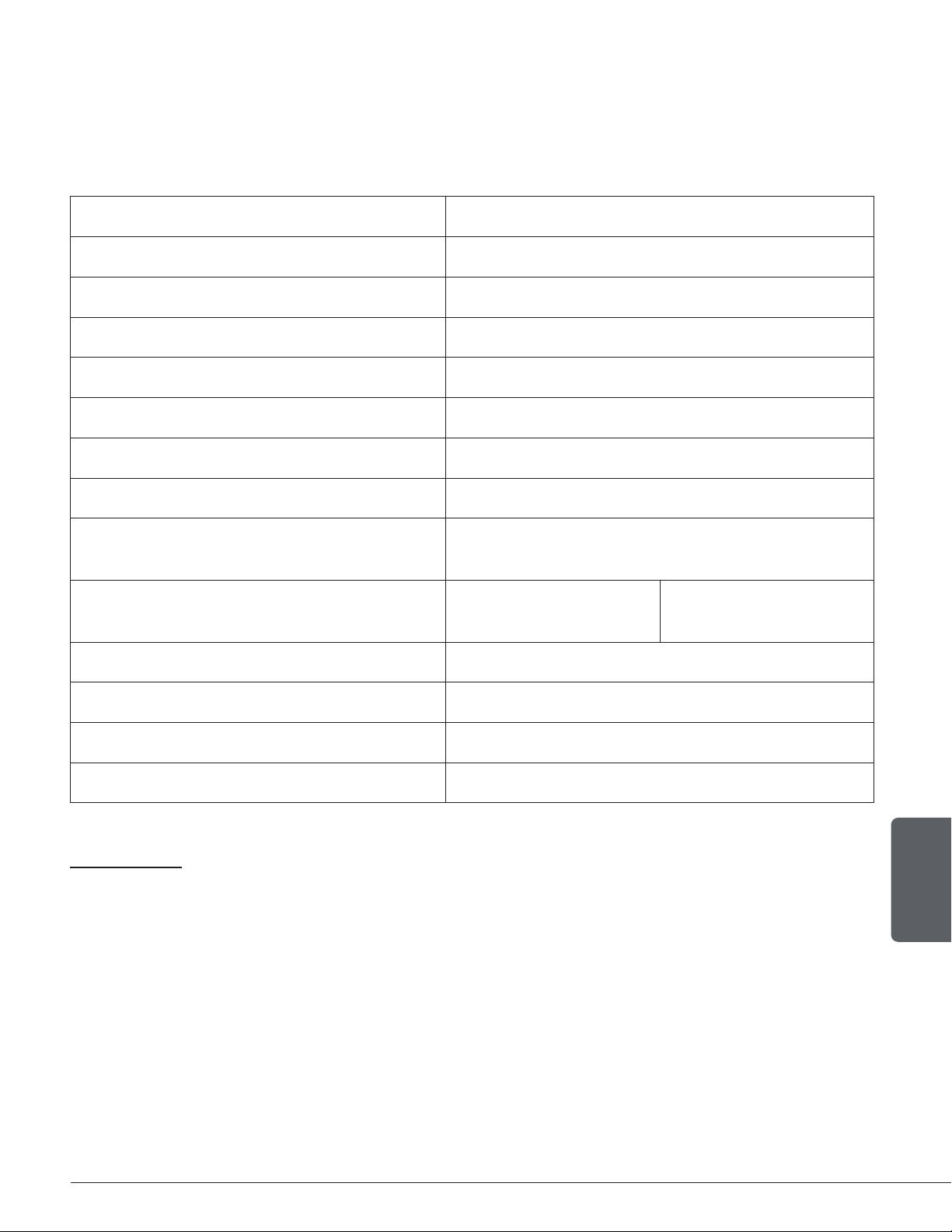
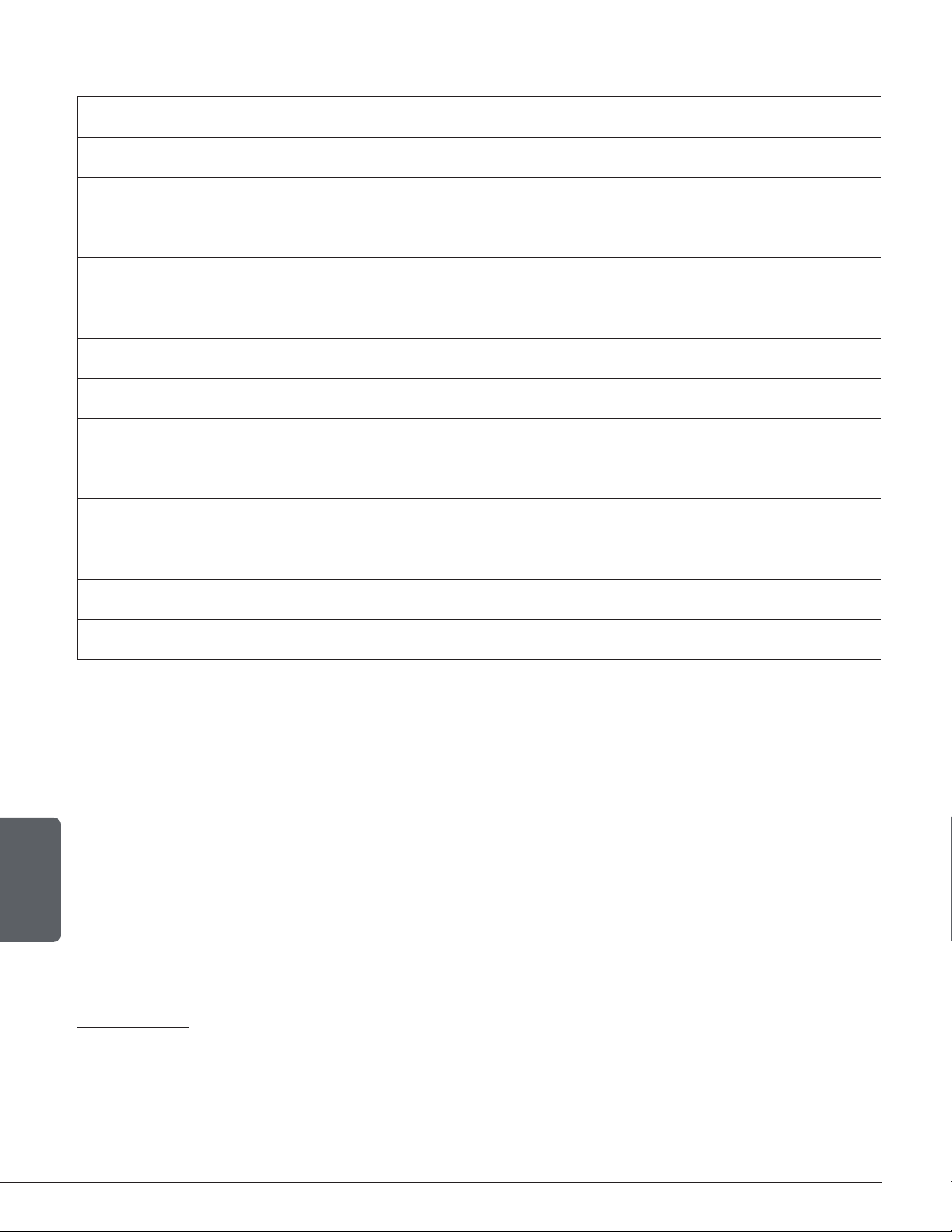
2.1 Performances
Values are as measured per test method, except for the recommended heating area, firebox volume,
maximum burn time and maximum heat output.
Model Blue Ridge 100 (ESW0001)
Type of combustion Non-catalytic
Fuel Type Dry Cordwood
Recommended heating area (sq. ft..)1 250 to 1,200 ft2(23 to 111 m2)
Overall firebox volume21.8 ft3(0.0510 m3)
EPA Loading volume 1.55 ft3(0.0439 m3)
Maximum burn time15 hours
Maximum heat output (dry cordwood)3 45,000 BTU/h (13.2 kW)
Overall heat output rate (min. to max.)2 4 12,124 BTU/h to 26,700 BTU/h
(3.55 kW to 7.83 kW)
Average overall efficiency3
(Dry cordwood) 74 % (HHV)5 79 % (LVH)6
Optimum efficiency7 80 %
Optimum overall efficiency8 79 %
Average particulate emissions rate9 1.8 g/h (EPA / CSA B415.1)10
Average CO11 74 g/h
1Recommended heating area and maximum burn time may vary subject to location in home, chimney draft,heat loss factors, climate, fuel type
and other variables. The recommended heated area for a given appliance is dened by the manufacturer as its capacity to maintain a minimum
acceptable temperature in the designated area in case of a power failure.
2The overall rebox calculation is an approximation and is not intended to be used for loading. This volume includes a buffer zone to allow an easier
fuel insertion, prevent ash spillage and allow the air wash to work properly.
3The maximum heat output (dry cordwood) is based on a loading density varying between 15 lb/ft3and 20 lb/ft3. Other performances are based on
a fuel load prescribed by the standard. The specied loading density varies between 7 lb/ft³ and 12 lb/ft3. The moisture content is between 19%
and 25%.
4As measured per CSA B415.1 stack loss method.
5Higher Heating Value of the fuel.
6Lower Heating Value of the fuel.
7Optimum overall efciency at a specic burn rate (LHV).
8The optimum heat transfer efciency is for the low burn rate and represents the appliance's ability to convert the energy contained in the wood logs
into energy transferred to the room in the form of heat and does not take into account the chemical losses during combustion.
9This appliance is ofcially tested and certied by an independent agency.
10 Tested and certied in compliance with CFR 40 part 60, subpart AAA, section 60.534(a)(1(ii) and ASTM E3053 based on the ALT-125 sent by EPA on
February 28th, 2018.
11 Carbon monoxide.