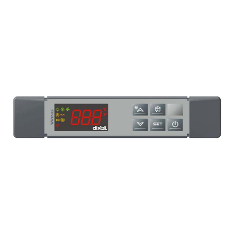
aditec ETA 110 User manual

Temperature Controller ETA 110
_________________________________________________________________________________________________________
_________________________________________________________________________________
04.06.09 page 1
ETA110 V03 Operating manual 04.06.09
The ETA 110 works as a heating- or cooling controller. A second relay can be used as either
an operating, alarm, upper limit or lower limit relay.
The heating control can work in either two point-, XP or interval operation.
The nominal value limit for the temperature can be set by using a code.
When the controller is switched on while the buttons „Plus“ and „Minus“ are pressed
simultaneously, the nominal temperature value is reset to „0“.
The actual temperature is shown in the upper display and the nominal temperature in the lower
display.
As soon as the controller has been connected to the mains it is in operating mode. (Please note:
also see “setting options” under code „100“).
The nominal temperature can be set within the programmed limits by using the „Plus“- and
„Minus“ buttons.
Code entry : press the two buttons on the outer left and right simultaneously, for ca. 3
seconds. The lower display will show „Cod“. Use the „Plus“ and „Minus“ buttons to set the code
numbers (upper display). Confirm the code by pressing the same outer buttons again. To quit
the code, press these two buttons yet again.
Activation or deactivation of the outer left button: Code 100
Upper display shows „StP“.
Choose between „OFF“ (deactivated) and „On“ (activated) by using the arrow
buttons.
Be aware: the following only applies when the button on the outer left has been
activated:
Display –actual
temperature
Display -nominal
temperature
button outer
left
button
outer right
arrow
buttons
plus/minus
1
2

Temperature Controller ETA 110
_________________________________________________________________________________________________________
_________________________________________________________________________________
04.06.09 page 2
- In operating mode, the temperature values can only be changed transiently,
this means that at the next programme start the controller will revert to
working with the value that had originally been entered in programming
mode.
- The code setting can not be changed while the controller is in operation.
Setting function „Relay 1“ heating or cooling: Code 101
Upper display shows „rL1“. Choose between „HEA“ (heating) and „Coo“(cooling)
Choose the setting with the buttons plus/minus
Setting function „Relay 2“ as alarm signal, operation or upper-/lower limit value: Code 102
Upper display shows „rL2“. Choose between “Alr“ (alarm signal), „OPE“
(operation) and „LCo“ (limit comparator)
Choose the setting with the buttons plus/minus
Functions of relays K1 and K2 can be interchanged: Code 105
Upper display: „SrL“ (switch relays). Choose between „on“ (functions are
interchanged) and „off“ (functions are not interchanged). The relay displays in
codes 101 and 102 will be changed accordingly.
Basic setting: „off“
The function of the heating control: Code 111
can be pre-set for example to avoid exceeding the nominal value. There are three
options of how to set the heating control:
2-point controller
When the actual value reaches the nominal value,
the output relay will switch off. The relay will only
switch back on, when the actual value falls below
the nominal value plus the hysteresis.
Xp-controller
While the actual value is within the control range,
the output relay clocks, - here the switch-on interval
depends on the electrical off-set. The control range,
the basic time interval (the sum of switch-on and
switch-off interval) for these clocking intervals, and
a minimum switch-on time can be pre-set. The
minimum switch-on interval cannot be longer than
half the basic time!
Clocking controller
While the actual value is within the control range the
output relay clocks at pre-set switch-on - and off
intervals. The control range and the switch on and
off intervals can be pre-set.
temperature
rel.switch-on interv
100%
50%
control range
temperature
on
Nom. value
hysteresis
T out in sec.
temperature
clocking range in sec.
T on in sec.

Temperature Controller ETA 110
_________________________________________________________________________________________________________
_________________________________________________________________________________
04.06.09 page 3
When selecting a heating controller, there are 3 parameters to choose from. Their significance
is shown in the table below:
Code 111:
Switching type
Parameter 1
Parameter 2
Parameter 3
Type of heating
control
2-point controller
Hysteresis in °C
-
-
Xp controller
Control range in
°C
Basic time
interval in sec.
Min. switch-on time sec.
Clocking
controller
Control range in
°C
Switch-on time
in sec.
Switch-off time in sec.
The factory setting is 2-point controller with a hysteresis of 1°C.
Choose the parameter settings by using the outer button on the right: display shows „HE0“
to „HE3“. Parameter is shown in the upper three-digit display.
„HE0“: choose the switching type : 2-point(„2Pt“), XP („HP“) or interval („Int“)
„HE1“: setting parameter 1
„HE2“: setting parameter 2
„HE3“: setting parameter 3
Setting the upper- and lower limits (limit comparators): Code 113
Display shows „LCo“
Upper display shows difference to the nominal temperature value.
Minus sign in front of the number: lower limit
Plus sign in front of the number: upper limit
Setting and activating the 3 levels heating: Code 119
The graded 3-level heating has a nominal temperature value and two difference
values. These difference values for the temperature are entered under code 119.
Once the graded heating is activated, you are restricted to entering only the 2-
point behaviour with hysteresis under Code 111 and under Code 101 only the
heating „HEAt“.
If the actual temperature is above the nominal temperature value, both relays are
inactive. Within the first temperature window d1 (see diagram) relay 1 is
energised, within the second temperature window d2, relay2 is energised and
below the second temperature window both relays are energised.
Example graded heating
T in °C
Rel 1&2 off
Temp.-nom.v.
d1 Rel 1 on 10°C
d2 Rel 2 on 10°C
Rel 1& 2 on
After the code entry „SSH“ (select step heat) will appear in the upper display and
„On“ or. „OFF“ respectively. Use the „Plus“ button to select „On“ (enabled), use
the „Minus“ button to select „OFF“ (disabled).
30
50
40

Temperature Controller ETA 110
_________________________________________________________________________________________________________
_________________________________________________________________________________
04.06.09 page 4
Use the buttons „outer right“ to set the difference values. Display shows „d1“ or
„d2“. Now make your entry, in a range from 0 to 100°C, using the arrow buttons.
Setting the upper temperature limit: Code 302
Display shows „HIG“
Range from 30°C to 400°C
Software version is shown (for a few seconds): Code 678
(e.g. Uer 10.0)
Digital offset adjustment: Code 777
The temperature sensor is shown in the upper left display „1“ or „2“.
Use the outer left button - „2“ has no meaning.
The actual current temperature is shown in the lower display. The upper left
display shows the value of the hundreds.
Make the offset adjustment by using the „Plus“ and „Minus“ buttons
Load default factory setting: Code 993
(display “InI“)
Load by using the outer left button
Standard default settings are:
-Code 100 „left outer“ button not active (OFF)
-Code 101 : heating
-Code 102 : upper-/lower limit (Limit comparators)
-Code 111: 2-point, 1°C hysteresis
-Code 113: 0°C
-Code 119: OFF
-Code 302: 400°C
Connection diagram:
Error messages:
Malfunctions of the temperature sensor are shown in the display for the actual temperature:
„EEE“ means sensor break
„- - - „ means short circuit in the sensor
ETA 110
230V AC
PE L1 N
04
03
02
01
08
07
06
05
12
11
10
09
14
13
K1: heating or cooling
K2: upper-/lower value,
operation or signal
chamber
Pt100
K2
K1

Temperature Controller ETA 110
_________________________________________________________________________________________________________
_________________________________________________________________________________
04.06.09 page 5
Safety instructions
To avoid any danger of electrocution, the housing must never be removed nor opened at the back. There
are no parts inside that can be serviced by the user himself. Leave the servicing to the experts! To avoid
a fire or electrocution the appliance must not get wet nor be exposed to rain.
1. Advice: Read all safety instructions and all items in the user manual, before using the controller for the
first time! Keep the safety instructions and the user manual in a safe place in case you need to refer back
to it at a later date!
2. Installation instructions: Always make sure that the appliance is installed by an authorized and
experienced specialist. Please follow the specific safety instructions as well as the VDE guidelines during
installation. The appliance should only be fitted in an approved and specifically designed waterproof
switching cabinet (metal housing) and should only be used for the purpose it was designed for and within
the limits of its technical data.
We recommend that any down-streamed inductors with RC elements should be checked for
interference. These are available on the retail market (e.g. Siemens 3 RT1916).
3. Analogue in- and outputs: To the in- and outputs (4-20mA / 0-10V and Pt100) do not apply separate
source voltage.
4. Sensor leads: The leads for the sensors should be run separately from any voltage carrying
leads, this also includes control wires carrying separate source voltage. It is vitally important that
the sensor leads have a metal shielding and that this shielding is connected to the sensor
housing itself.
5. Relay outputs: The relay outputs are potential free and the maximal load of 250V AC and 4A must not
overshoot.
6. Water and humidity: Never use the unprotected appliance near water, e.g. near a bath tub, water
basin, sink, washing machine, a damp cellar or near a swimming pool. The appliance is only waterproof
on the front (IP67). The back and side panels must not come into contact with water.
7. Ventilation: The appliance must have sufficient ventilation, the ventilation slits in the housing must
never be covered up, or blocked by objects that may have been inserted into the slits.
8. The effects of heat: Keep the appliance away from heat sources, like radiators, heating conduits,
ovens, and other elements that may radiate heat.
9. Energy sources: The appliance should only be connected to the power sources that are specified in
the service manual or on the appliance housing itself.
10. Cleaning: When cleaning the appliance, keep to the recommendations given by the manufacturer.
11. Appliance not in use: When you know the appliance is not going to be used for a longer period of
time, it should be disconnected from the mains.
12. Contaminants: You have to be extremely careful that neither liquids nor foreign objects can get into
the appliance through the openings in the housing. If objects or liquids have contaminated the inside of
the appliance, it has to be disconnected and sent in to the manufacturer immediately.
13. Servicing after damage: The appliance may only be serviced by a qualified specialist. The user
should only do the servicing tasks he is meant to do according to the service manual. For servicing that
exceed his authority, he should always contract a specialist.
14. Please note: Never make any technical alterations to the appliances, unless they were
specifically approved by aditec GmbH. Unauthorized alterations will invalidate your warranty.

Temperature Controller ETA 110
_________________________________________________________________________________________________________
_________________________________________________________________________________
04.06.09 page 6
For any questions, orders and repairs please contact our customer service team at the address below:
Measurment & control
Process controls
Hardware development
Software development
Specialized electronics
Food-Technology
Process-Visualization
aditec gmbh
Talweg 17
D-74254 Offenau
Tel.:+49(0)7136-96122-0
Fax:+49(0)7136-96122-20
www.aditec.net
aditec
CONTROLS for
FOODTECHNOLOGY
Table of contents
Popular Temperature Controllers manuals by other brands
Mitsubishi
Mitsubishi A1S62TCTT-S2 user manual
Hubbell
Hubbell GAI-TRONICS TempSense TS100 manual
Clint
Clint floyd FVW Series Instructions for installation, use and maintenance manual
aci
aci BACnet Series Installation & operation instructions
hanshow
hanshow Nebular-T01-N product manual
Qlima
Qlima DD 108 White operating manual
Velleman
Velleman K641LX Assembly guide
Uponor
Uponor UponorControl System Installation and operation manual

Mitsubishi Electric
Mitsubishi Electric PAC-USWHS003-TH-1 Installation instructions manual
Calex
Calex PyroSigma Series Operator's guide
WIKA
WIKA TC47 Series operating instructions
HARRICK
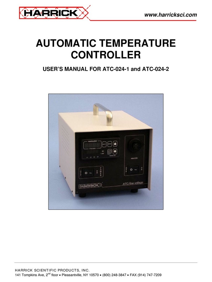
HARRICK ATC-024-1 user manual
