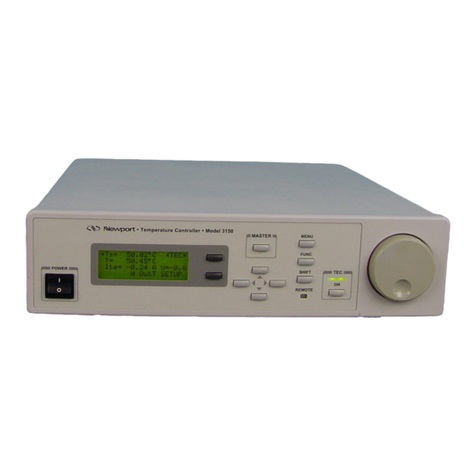
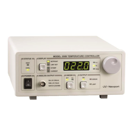
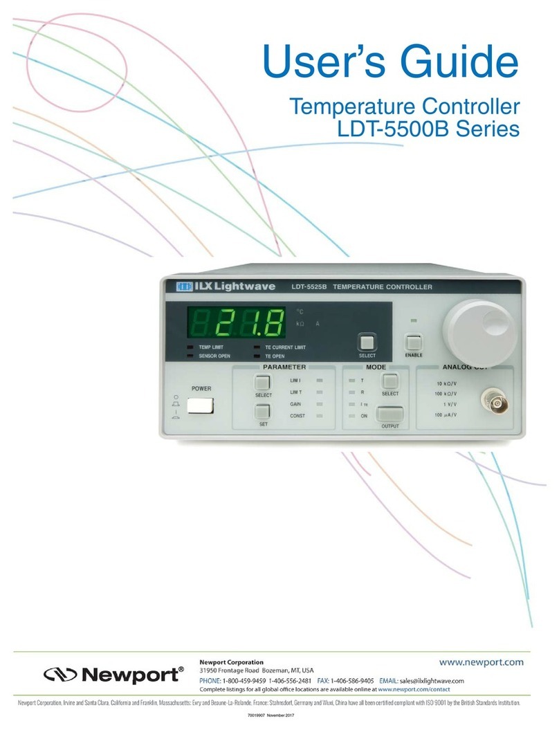
Newport 300 Series User manual

Artisan Technology Group is your source for quality
new and certied-used/pre-owned equipment
• FAST SHIPPING AND
DELIVERY
• TENS OF THOUSANDS OF
IN-STOCK ITEMS
• EQUIPMENT DEMOS
• HUNDREDS OF
MANUFACTURERS
SUPPORTED
• LEASING/MONTHLY
RENTALS
• ITAR CERTIFIED
SECURE ASSET SOLUTIONS
SERVICE CENTER REPAIRS
Experienced engineers and technicians on staff
at our full-service, in-house repair center
WE BUY USED EQUIPMENT
Sell your excess, underutilized, and idle used equipment
We also offer credit for buy-backs and trade-ins
www.artisantg.com/WeBuyEquipment
REMOTE INSPECTION
Remotely inspect equipment before purchasing with
our interactive website at www.instraview.com
LOOKING FOR MORE INFORMATION?
Visit us on the web at www.artisantg.com for more
information on price quotations, drivers, technical
specications, manuals, and documentation
Contact us: (888) 88-SOURCE | sales@artisantg.com | www.artisantg.com
SM
View
Instra

Model 300 Series
Temperature Controllers
OPERATING
MANUAL
DISPLAYSTATUS
POWER ANALOG OUTPUT MODE OUTPUT
10kΩ/V (100µA)
100kΩ/V (10µA)
100°C/V (335/590)
HEAT
COOL
PRESET
SENSOR
CURRENT
LIMIT
R/T ITE ON
ERROR
LIMITING
LIMIT SET
KΩ
°C
Amp
MODEL 325 TEMPERATURE CONTROLLER
Artisan Technology Group - Quality Instrumentation ... Guaranteed | (888) 88-SOURCE | www.artisantg.com

Model 300 Series Temperature Controllers
Operating Manual
Artisan Technology Group - Quality Instrumentation ... Guaranteed | (888) 88-SOURCE | www.artisantg.com

ii
Warranty
Newport Corporation warrants this product to be free from defects in
material and workmanship for a period of 1 year from the date of shipment.
If found to be defective during the warranty period, the product will either
be repaired or replaced at Newport’s option.
To exercise this warranty, write or call your local Newport representative,
or contact Newport headquarters in Irvine, California. You will be given
prompt assistance and return instructions. Send the instrument, transpor-
tation prepaid, to the indicated service facility. Repairs will be made and
the instrument returned, transportation prepaid. Repaired products are
warranted for the balance of the original warranty period, or at least 90
days.
Limitation of Warranty
This warranty does not apply to defects resulting from modification or
misuse of any product or part. This warranty also does not apply to fuses.
This warranty is in lieu of all other warranties, expressed or implied,
including any implied warranty of merchantability or fitness for a particular
use. Newport Corporation shall not be liable for any indirect, special, or
consequential damages.
ii
© 1995 Newport Corporation
1791 Deere Ave
Irvine, CA 92606
(949) 863-3144
P/N 21206-01, Rev. B
IN-04952 (10-99)
Artisan Technology Group - Quality Instrumentation ... Guaranteed | (888) 88-SOURCE | www.artisantg.com

iii
VP European Operations General Manager-Precision Systems
Zone Industrielle 1791 Deere Avenue
45340 Beaune-la-Rolande, France Irvine, Ca. USA
We declare that the accompanying product, identified with the
"" mark, meets the intent of the Electromagnetic Compatability
Directive, 89/336/EEC and Low Voltage Directive 73/23/EEC.
Compliance was demonstrated to the following specifications:
EN50081-1 EMISSIONS:
Radiated and conducted emissions per EN55011, Group 1,
Class A
EN50082-1 IMMUNITY:
Electrostatic Discharge per IEC 1000-4-2, severity level 3
Radiated Emission Immunity per IEC 1000-4-3, severity level 2
Fast Burst Transients per IEC 1000-4-4, severity level 3
Surge Immunity per IEC 1000 4-5, severity level 3
IEC SAFETY:
Safety requirements for electrical equipment specified in
IEC 1010-1.
Alain Danielo Jeff Cannon
EC DECLARATION OF CONFORMITY
Active Isolation Module Set Series
Artisan Technology Group - Quality Instrumentation ... Guaranteed | (888) 88-SOURCE | www.artisantg.com

iv
Table of Contents
Warranty ................................................................................................................ii
Figures ...................................................................................................................iv
Safety Precautions ...............................................................................................iv
Section 1 — General Information 1
1.1 Introduction .............................................................................................. 1
1.2 Specifications ............................................................................................ 1
1.3 Accessories ............................................................................................... 3
Section 2 — System Operation 4
2.1 Introduction .............................................................................................. 4
2.2 Front Panel ................................................................................................ 4
2.2.1 AC Power Switch ............................................................................ 5
2.2.2 Analog Output................................................................................. 5
2.2.3 Mode Switch.................................................................................... 5
2.2.4 Output Section ................................................................................ 5
2.2.5 Status ............................................................................................... 5
2.2.6 Display ............................................................................................. 5
2.2.7 Control Knob................................................................................... 6
2.3 Rear Panel.................................................................................................. 7
2.3.1 Analog Interface ............................................................................. 7
2.3.2 Gain Adjust...................................................................................... 9
2.3.3 Sensor Select Switch...................................................................... 9
2.3.4 Output Connector .......................................................................... 9
2.3.5 AC Power Inlet ................................................................................ 9
Section 3 — Principles of Operation 10
3.1 Introduction ............................................................................................ 10
3.2 Thermistors............................................................................................. 10
3.3 Working With IC Sensors .......................................................................11
3.3.1 AD590 SERIES IC SENSORS.......................................................... 11
3.3.2 LM335 SERIES IC SENSORS.......................................................... 11
3.4 Using Thermo-Electric Modules ........................................................... 11
3.5 Mounting Considerations ...................................................................... 13
3.6 Model 300 Series Setup.......................................................................... 13
3.6.1 Rack Mounting Model 300 Series Units ...................................... 13
3.6.2 Model 300 Series Operating Checklist ........................................ 14
Section 4 — Factory Service 16
4.1 Introduction ............................................................................................ 16
4.2 Obtaining Service ................................................................................... 16
Service Form ........................................................................................... 17
Artisan Technology Group - Quality Instrumentation ... Guaranteed | (888) 88-SOURCE | www.artisantg.com

v
Figures
Figure 1 Front panel layout................................................................................ 4
Figure 2 Rear panel layout................................................................................. 7
Figure 3 TE module configuration .................................................................. 12
Figure 4 Mounting arrangement of a TE module,
heat sink and laser diode.................................................................. 13
Figure 5 Gain Adjust Settings .......................................................................... 15
Safety Precautions
CAUTION
Check that all equipment is unplugged before connecting
Check that the selector is set at the position which corresponds to
your mains voltage
All units are factory preset to operate at 180–250 VAC, 50–60 Hz.
(See AC Power Inlet, in Section 2.3.5)
Artisan Technology Group - Quality Instrumentation ... Guaranteed | (888) 88-SOURCE | www.artisantg.com

vi
Notes
Artisan Technology Group - Quality Instrumentation ... Guaranteed | (888) 88-SOURCE | www.artisantg.com

1
Section 1
General Information
1.1 Introduction
Two controllers, the Model 325 and 350, provide superior temperature
stability and a wide range of power outputs. Each has a fast settling,
hybrid P-I control loop that delivers a low noise, bipolar current output in
three operating modes: 1) constant R (thermistor), 2) constant T (IC
sensors), or 3) constant ITE . A user adjustable ITE current limit setting
unconditionally protects the TE modules from damage by excessive drive
current independent of the operating mode. The Model 300 Series is
compatible with thermistors, and AD590 and LM335 Series IC temperature
sensors. Temperature readings (°C) are displayed when using one of these
IC sensors. Model 325 AN and 350 AN include an Analog Interface allowing
remote instrument control and monitoring of display levels.
1.2 Specifications
Model 325 Model 350
Model 325AN Model 350AN
Output
Output Type Bipolar, constant current source Bipolar, constant current source
Control Loop Type Hybrid P-I Hybrid P-I
Maximum Current ±2.5 Amps ±5 Amps
Compliance Voltage >6 Volts >10 Volts
Available Output Power 15 Watts 50 Watts
Current Limit
Range 0 to 2.5 Amps 0 to 5 Amps
Accuracy ±10 mA ±20 mA
Ripple/Noise (rms) <1 mA <2 mA
Stability
Short Term (10 to 30 min.) 0.005 °C 0.005 °C
Long Term (24 hour period) 0.01 °C 0.01 °C
Artisan Technology Group - Quality Instrumentation ... Guaranteed | (888) 88-SOURCE | www.artisantg.com

2
Model 325 Model 350
Model 325AN Model 350AN
Display
Range:
Temperature −50.0 to +150.0°C −50.0 to +150.0°C
Resistance (10 µA) 0.1 kΩto 199.9 kΩ0.1 kΩto 199.9 kΩ
Resistance (100 µA) 0.01 kΩto 19.99 kΩ0.01 kΩto 19.99 kΩ
TE Current −2.50 Amps to +2.50 Amps −5.00 Amps to +5.00 Amps
Resolution:
Temperature 0.1°C 0.1°C
Resistance (10 µA) 100 Ω100 Ω
Resistance (100 µA) 10 Ω10 Ω
TE Current 10 mA 10 mA
Accuracy:
Temperature ±0.2 °C ±0.2 °C
Resistance (10 µA) ±200 Ω±200 Ω
Resistance (100 µA) ±20 Ω±20 Ω
TE Current ±10 mA ±20 mA
Temperature Sensors
Sensor Types Thermistor (NTC 2-wire) AD590 LM335
Temperature Resolution 0.1 °C 0.1 °C 0.1 °C
Temperature Accuracy (at 25°C) 0.2 °C 0.5 °C 3.0 °C
Sensor Bias 10 µA/100 µA +12 Volts 1 mA
General
Input Power 90–125, 180–250 VAC, 50–60 Hz
Chassis Ground 4 mm banana jack
Size, H x W x D 88 x 215 x 280 mm
(3.5" x 8.5" x 11")
Weight
Model 325 & 350 2.9 kg (6.5 lbs.)
Operating Temperature 0°C to +50°C
Storage Temperature −40°C to +70°C
Humidity <90% relative, non-condensing
Connectors
Output 15-pin, D-sub (female)
Analog Output Isolated BNC
Analog Interface
(Model 325AN & 350AN) 15-pin, high density D-sub (female)
Artisan Technology Group - Quality Instrumentation ... Guaranteed | (888) 88-SOURCE | www.artisantg.com

3
1.3 Accessories
The Model 300 Series Temperature Controllers come with a line cord for
connection to AC power. To order accessories use the following part
numbers:
PART # DESCRIPTION
300-02 Temperature Controller Cable
300-04 Temperature Controller/Mount Cable
300-16 10.0 kΩthermistor (±0.2°C)
300-22 AD592CN IC Sensor
35-RACK Rack Mount Kit
Artisan Technology Group - Quality Instrumentation ... Guaranteed | (888) 88-SOURCE | www.artisantg.com

4
Section 2
System Operation
2.1 Introduction
The Model 300 Series Temperature Controllers have been engineered to
simplify the use of thermoelectric (TE) modules for cooling or heating laser
diodes, IR detectors and other semiconductor devices.
2.2 Front Panel
The front panel is outlined with six functional areas and a multi-turn
control knob used to set a stable output value.
DISPLAYSTATUS
POWER ANALOG OUTPUT MODE OUTPUT
10kΩ/V (100µA)
100kΩ/V (10µA)
100°C/V (335/590)
HEAT
COOL
PRESET
SENSOR
CURRENT
LIMIT
R/T ITE ON
ERROR
LIMITING
LIMIT SET
KΩ
°C
Amp
MODEL 325 TEMPERATURE CONTROLLER
Figure 1: Front panel layout
Artisan Technology Group - Quality Instrumentation ... Guaranteed | (888) 88-SOURCE | www.artisantg.com

5
2.2.1 AC Power Switch
When the AC power is turned on the unit starts up with the OUTPUT off,
R/T MODE selected, and the display in the PRESET mode.
2.2.2 Analog Output
A BNC connector can be used to monitor the temperature sensor value.
The transfer function of the output is dependent on the sensor type se-
lected. The thermistor current selection values are either 10µA or 100µA
and result in either 100 kΩ/V or 10 kΩ/V respectively. Both IC sensors have
a transfer function of 100°C/V.
2.2.3 Mode Switch
The Model 300 Series can be operated in either 1) constant R (thermistor
resistance), 2) constant T (IC sensors), or 3) constant ITE mode. The R/T
mode is used with temperature sensors and the ITE mode to maintain a
constant output current.
2.2.4 Output Section
Output ON Switch
Pushing this switch allows current flow to the TE module. The output stays
on, as indicated by the green LED above, until the switch is pushed again or
an error condition occurs.
Error Indicator LED
An ERROR condition occurs when there is an open circuit to the TE module
or temperature sensing device. The output current is automatically turned
off. Once the device is replaced or reconnected, pushing the output switch
twice will clear the error indication and restore the output on condition.
Limiting Indicator LED
This LED lights up whenever the output current reaches a user adjustable
threshold, limiting the current flow to the TE module. It usually occurs
during initial startup as the drive circuitry attempts to reach equilibrium.
Limit Set
A small slotted screwdriver is used to access a recessed trimpot to adjust
the unit’s output current limiting level. Toggle the DISPLAY section push-
button to the LIMIT indicator and adjust the readout (in Amps) with a
clockwise rotation to increase the protection level.
2.2.5 Status
The STATUS indicator LEDs show whether the device under temperature
control is being heated or cooled.
2.2.6 Display
A 3 1/2 digit green LED display is located in the top center of the front
panel. It reads in kΩwhen displaying a thermistor resistance value, °C
when displaying an IC sensor temperature, or Amps when in the constant
current ITE mode. Pushing the switch cycles through the display values as
described below. Display modes can be toggled with the output on or off.
Artisan Technology Group - Quality Instrumentation ... Guaranteed | (888) 88-SOURCE | www.artisantg.com

6
Preset Display
The PRESET display mode is used to set the appropriate output value using
the rotary control knob before turning the OUTPUT on. Once the control
level is set, the OUTPUT may be turned on and the actual SENSOR or
CURRENT value can be monitored.
Sensor Display
The actual temperature sensor value is monitored in this mode. The value
displayed depends on the sensor being used with °C displayed for IC
sensors and kΩfor thermistors.
Current Display
This readout monitors the actual current level in Amps being supplied to
the TE module. When the OUTPUT is first selected this current value may
be as high as the LIMIT value. As the temperature stabilizes the output
current will decrease.
Limit Display
This value is set by the limit set screw adjustment. See Limit Set, 2.2.4.
Indicator LEDs
To the right of the numeric display are three LEDs which indicate measure-
ment units: 1) resistance in kΩ, 2) temperature in °C, or 3) output current in
Amps.
2.2.7 Control Knob
The knob control on the right side of the front panel sets the appropriate
reference value corresponding to either resistance (thermistor), tempera-
ture (IC sensors), or TE current (ITE) to be maintained by the Model 300
Series Temperature Controller.
Artisan Technology Group - Quality Instrumentation ... Guaranteed | (888) 88-SOURCE | www.artisantg.com

7
2.3 Rear Panel
Figure 2 shows the layout of the rear panel which contains the ANALOG
INTERFACE and OUTPUT connectors, a REMOTE/ LOCAL switch, the
sensor select switch, GAIN ADJUST screw, and the AC power inlet.
ANALOG
INTERFACE
OUTPUT
1,2
3,4
5
6
7
8
TE (+)
TE (–)
TE SHIELD
SENSOR SHIELD
SENSOR (+)
SENSOR (–)
GAIN
ADJUST
REMOTE
LOCAL
115/230, 2A/1A, 60/50 Hz
250V, 3AG, SLO-BLOW
MADE IN U.S.A.
CAUTION: DO NOT REMOVE COVER, REFER SERVICING TO QUALIFIED
PERSONNEL. DISCONNECT INPUT POWER BEFORE REPLACING FUSE
OFF
ON
OFF
ON
SENSOR SELECT
100µA10µA LM335 AD590
OFF
OFF ON
OFF OFF
ON ON
ON 115V
Figure 2: Rear panel layout.
2.3.1 Analog Interface
Model 325AN and 350AN include a Analog Interface card, located at the far
left of the rear panel. A 15-pin, high density, D-sub connector is used for
the input and output lines. Above the connector is the REMOTE/LOCAL
switch used to activate the set-point control line which is disabled in the
LOCAL mode. The status lines are always available whether the REMOTE
or LOCAL mode is selected.
How To Use The Analog Interface
The Analog Interface may be used with chart recorders, X-Y recorders or
can be operated via a computer using a multiple function I/O card such as
the National Instruments LAB-PC data acquisition card. One data acquisi-
tion card will control two Model 300 temperature controller units or one
Model 300 and one Model 500 laser diode driver unit. The Output Set-point
is set using one of the analog outputs from the data acquisition card. Other
TTL signals of the Analog Interface card are controlled by the digital I/O
lines. R/T Monitor data, such as temperature, is then acquired using the
analog input line of the data acquisition card.
Artisan Technology Group - Quality Instrumentation ... Guaranteed | (888) 88-SOURCE | www.artisantg.com

8
Analog Interface Connections
Pin # Designation Function
1 ON/OFF TTL momentary low toggles output on/off
2 ENABLE TTL low = remote level control enabled*
3 STATUS TTL low = output on
4 LIMIT TTL low = output limiting
5 ERROR TTL low = output error
6 MODE TTL low = R/T, TTL high = ITE
7 DGND Digital Common for TTL signals
8 EGND Earth Ground for shielding TTL signals
9 LEVEL (+) Input signal for level control (charts below)*
10 LEVEL (−) Input signal DC Common
11 ANALOG OUT DC output voltage for actual R/T (chart below)
12 AGND DC Common for Analog Output
13 - Not Used
14 - Not Used
15 EGND Earth ground for shielding analog signals
* Front panel control knob is bypassed
External Level Input, VDC (Pin 9 With Respect To Pin 10)
R/T MODE
Range Input Voltage Level Corresponding R/T Value
100µA 0 to 2V 0 to 20 kΩ
10µA 0 to 2V 0 to 200 kΩ
AD590 −0.50V to +1.50V −50.0°C to +150°C
LM335 −0.50V to +1.50V −50.0°C to +150°C
ITE MODE
Model Input Voltage Level Output Current Level
325/325AN −250 mV to +250 mV −2.50 A to +2.50 A
350/350AN −500 mV to +500 mV −5.00 A to +5.00 A
Analog Output Level, VDC (Pin 11 With Respect To Pin 12)
R/T or ITE MODE
Range Output Voltage Level Corresponding R/T Value
100µA 0 to 2V 0 to 20 kΩ
10µA 0 to 2V 0 to 200 kΩ
AD590 −0.50V to +1.50V −50.0°C to +150°C
LM335 −0.50V to +1.50V −50.0°C to +150°C
Artisan Technology Group - Quality Instrumentation ... Guaranteed | (888) 88-SOURCE | www.artisantg.com

9
2.3.2 Gain Adjust
The GAIN ADJUST varies the overshoot and stability of the control loop
circuitry in order to accommodate different thermal characteristics of
thermistors, the TE module and heatsink, and mounting structures.
Sections 3.2, 3.3, 3.4 and 3.5 present the details of using TE modules, IC
sensors, thermistors, and how physical mounting arrangements affect the
operation of the Model 300 Series Temperature Controllers. An initial GAIN
value is set at the factory and should be satisfactory for most mounts.
Adjusting the GAIN is described in Section 3.6.2 (i).
2.3.3 Sensor Select Switch
This 2-position DIP switch is used to select the appropriate bias for each
one of the sensor types. The switch position for each sensor is printed on
the rear panel next to the switch.
2.3.4 Output Connector
Connection to the TE module and temperature sensor are made using a 15-
pin, D-sub connector. There are two pins each for the TE+and TE−connec-
tions to provide redundancy and reduce the voltage drop in the cable.
Wire Color
Pin # Connection (300-02 cable)
1 & 2 TE +RED
3 & 4 TE −BLACK
5 TE SHIELD
6 SENSE SHIELD
7 SENSOR +GREEN
8 SENSOR −WHITE
2.3.5 AC Power Inlet
The input voltage setting is indicated in a small window on the face of the
power module. A small screwdriver is needed to flip down the panel once
the AC line cord is removed. Carefully rotate the plastic tumbler so the
proper range is indicated. The fuse is also located behind this panel and
can be pulled out, to be replaced with the appropriate size indicated on the
back panel.
All units are preset at the factory for operation at 180–250 VAC, 50–60 HZ.
The line cord supplied with each unit should be plugged only into a prop-
erly grounded three prong outlet to prevent electrical shock in the event of
an internal short circuit to the metal cabinet.
Artisan Technology Group - Quality Instrumentation ... Guaranteed | (888) 88-SOURCE | www.artisantg.com

10
Section 3
Principles of Operation
3.1 Introduction
Three factors must be taken into account when optimizing the operation of
a Model 300 Series Temperature Controller: selection of both the appropri-
ate temperature sensor and TE module heat sink, and the manner in which
they are mounted. Selecting the proper thermistor to cover a specific
temperature range of operation is a simple but important procedure. The
proper TE module must be selected to remove the heat dissipated by the
laser diode or other device. Finally, the arrangement of the TE module and
the heat sink, as well as the heat sink size, are crucial in maximizing the
heat transfer efficiency.
3.2 Thermistors
Model 300 Series Temperature Controllers are designed to operate using a
thermistor as one of the temperature sensing devices. Temperature is
displayed as a resistance (kΩ) corresponding to the temperature of the
thermistor. The actual temperature of the thermistor can be determined from
the manufacturers curves or tables listing temperature vs. resistance. Two
precision current sources, 10µA and 100µA, are used to generate a voltage
across the thermistor and it is this voltage that is read on the front display.
For the 10µA current source the maximum resistance that can be displayed
is 199.9 kΩ, while for the 100µA source the maximum reading is 19.99 kΩ.
The minimum resistance value that can accurately be read is 200 ohms
(100µA current source). These two current values allow a wide range of
temperatures to be controlled by the Model 300 Series Temperature
Controllers. Different ranges of temperatures can be adjusted for by selecting
the proper thermistor value. The following table illustrates this point:
Temperature vs. Thermistor Resistance
Thermistor value @ 25°C 1k 10k 100k
200 kΩ–75°C –37°C –11°C
100 kΩ–66°C –24°C 25°C
20 kΩ–40°C 8°C 65°C
10 kΩ–27°C 25°C 85°C
1 kΩ25°C 93°C >150°C
100 Ω100°C >150°C >150°C
Artisan Technology Group - Quality Instrumentation ... Guaranteed | (888) 88-SOURCE | www.artisantg.com

11
Careful thermistor value selection therefore enables control over a wide
temperature range.
The temperature resolution and thermistor sensitivity must also be taken
into account. Thermistors achieve their highest sensitivity at the lower
end of their temperature range. Therefore, the lower the absolute tempera-
ture to be maintained, the lower the resistance value the thermistor should
be. For example, to operate at 0°C a 10k ohm thermistor would be the best
selection while at 100°C a 1k ohm thermistor would be a better selection.
The rule of thumb is to operate the thermistor near the lower end of its
temperature range and use the 100µA current bias. Please contact
Newport’s applications engineers if you have any questions regarding the
selection of the proper thermistor for your application.
3.3 Working With IC Sensors
Two IC temperature sensors may be used with the Model 300 Series Tem-
perature Controllers, the AD590 Series and the LM335 Series. Both come in
several different package types having various accuracy and stability
characteristics. These temperature sensors are easy to use and give a
temperature reading directly in °C on the Model 300 Series display.
3.3.1 AD590 SERIES IC SENSORS
The AD590 Series devices are two-terminal IC temperature sensing devices,
which produce an output current directly proportional to the absolute
temperature at 1µA/°K. The AD590 Series sensor is particularly useful in
remote sensing applications where long cable lengths are used, due to its
high impedance current output. A linear output is displayed in °C on the
Model 300 Series Temperature Controller, which makes it ideally suited for
most temperature sensing applications. The recommended upper operat-
ing limit for AD590 Series devices is 150°C.
3.3.2 LM335 SERIES IC SENSORS
The LM335 Series devices are similar to the AD590 in that they are two
terminal devices and their output is directly proportional to absolute
temperature. Operating like a two terminal zener diode, the LM335 Series
temperature sensors have a breakdown voltage directly proportional to
absolute temperature at +10mV/°K. When using the LM335 Series sensors,
voltage drops resulting from using long cables will introduce inaccuracies
in the temperature display measurement.
3.4 Using Thermo-Electric Modules
Thermo-electric (TE) modules are semiconductor devices that act as heat
pumps when a voltage is applied to them. This effect is called Peltier
cooling or heating. The direction of the current flow determines whether
the TE module is cooling or heating a device such as a laser diode or IR
detector. A TE module consists of a matrix of thermoelectric couples made
of p-type and n-type semiconductor material. A TE module can be fabri-
cated with as few as one couple or with as many as several hundred
couples sandwiched between two ceramic plates. The ceramic plates form
Artisan Technology Group - Quality Instrumentation ... Guaranteed | (888) 88-SOURCE | www.artisantg.com

12
the top and bottom of the TE module and provide structural integrity as
well as electrical insulation from, and thermal conduction to, the heat sink
and the device being cooled or heated.
Model 300 Series Temperature Controllers are designed to control the rate
and amount of cooling or heating through the use of a feedback loop. The
arrangement of the TE module in the cooling mode is shown in Figure 3.
When a positive DC voltage is applied to the n-type element, electrons pass
from the p-type to the n-type elements and the temperature decreases as
heat is absorbed by the cold side of the TE module. The heat absorbed is
proportional to the amount of current flowing through the TE module and
the number of p-type and n-type elements in the TE module.
+–
P-TYPE N-TYPE
Heat Dissapated To Heat Sink
Current Flow
Cooling Mode
Th (Hot Side)
Tc (Cold Side)
TE + (Pins 1, 2)
TE –(Pins 3, 4)
Heat Absorbed From Device Being Cooled
+–
Figure 3: TE module configuration
It is necessary to remove the heat from the hot side of the TE module. The
amount of heat to be dissipated is equal to the heat pumped from the cold
side plus the input power to the TE module. Although the amount of
cooling is proportional to the current flowing through the TE module, the
power dissipated by Joule heating (input power heating) in the TE module
is proportional to the square of the current. Half of this heat must be
pumped from the cold side of the TE module. When exceeding a maximum
current value (Imax), which is device dependent, the net cooling of the TE
module decreases because Joule heating is increasing at a greater rate than
Peltier cooling. The manufacturer of the TE module will state the maximum
current for each TE module and this current value should not be exceeded.
The LIMIT SET feature on the Model 300 Series Temperature Controllers
allows you to limit the maximum current flowing through the TE module.
Artisan Technology Group - Quality Instrumentation ... Guaranteed | (888) 88-SOURCE | www.artisantg.com
This manual suits for next models
4
Table of contents
Other Newport Temperature Controllers manuals
Popular Temperature Controllers manuals by other brands

J-KEM Scientific
J-KEM Scientific Gemini user manual
Sub-Zero
Sub-Zero SZ-81145 user manual
RKC INSTRUMENT
RKC INSTRUMENT REX-P48 Series Operation manual
alre
alre FTRFB-280 Series manual
Kingspan
Kingspan Temperature differential controller Installation and operating instructions
Saunier Duval
Saunier Duval exacontrol 7 manual
Stahl
Stahl 8146/5051 Series operating instructions
Sorel
Sorel MTDC Installation and operating instructions

STIEBEL ELTRON
STIEBEL ELTRON EASYTRON Connect ERT instructions
Viessmann
Viessmann VITOTROL 100 Operating Instructions for the System User
KIOUR
KIOUR RSD quick start guide
Ketotek
Ketotek KT1210W operating manual
