ADJ penta pix User manual

User Instructions
2/17
Penta Pix
©2017 ADJ Products, LLC all rights reserved. Information,
specications, diagrams, images, and instructions herein are
subject to change without notice. ADJ Products, LLC logo and
identifying product names and numbers herein are trademarks
of ADJ Products, LLC. Copyright protection claimed includes all
forms and matters of copyrightable materials and information
now allowed by statutory or judicial law or hereinafter granted.
Product names used in this document may be trademarks or
registered trademarks of their respective companies and are
hereby acknowledged. All non-ADJ Products, LLC brands and
product names are trademarks or registered trademarks of their
respective companies.
ADJ Products, LLC and all aliated companies hereby dis-
claim any and all liabilities for property, equipment, building, and
electrical damages, injuries to any persons, and direct or indi-
rect economic loss associated with the use or reliance of any
information contained within this document, and/or as a result
of the improper, unsafe, unsucient and negligent assembly,
installation, rigging, and operation of this product.
Europe Energy Saving Notice
Energy Saving Matters (EuP 2009/125/EC)
Saving electric energy is a key to help protecting the enviroment.
Please turn o all electrical products when they are not in use. To
avoid power consumption in idle mode, disconnect all electrical
equipment from power when not in use. Thank you!

ADJ Products, LLC - www.adj.com - Penta Pix Instruction Manual Page 3
• Built in Microphone
• 5 DMX Channel Modes: 4/8/11/20/27
• 63 Color Macros
• 4 Show Modes
• 5 Operational modes: Sound Active, Auto Run, RGBW Dimmer
Mode, Color Macro Mode, & DMX Control
• Sound Sensitivity Adjustable
• Power Cord Daisy Chaining. See page 23.
Penta Pix Warranty Registration
Penta Pix Features
To optimize the performance of this product, please read these operat-
ing instructions carefully to familiarize yourself with the basic operations
of this unit. These instructions contain important safety information
regarding the use and maintenance of this unit. Please keep this manual
with the unit, for future reference.
Penta Pix General Instructions
The Penta Pix carries a 3 year (1095 days) limited warranty. Please fill
out the enclosed warranty card to validate your purchase and war-
ranty. You may also register your product online at www.adj.com. All
returned service items whether under warranty or not, must be freight
pre-paid and accompany a return authorization (R.A.) number. If the
unit is under warranty you must provide a copy of your proof of pur-
chase invoice. Please contact ADJ Products, LLC customer support
for a R.A. number.
Penta Pix Installation
The unit should be mounted using a mounting clamp (not provided),
axing it to the mounting bracket that is provided with the unit.
Always ensure that the unit is rmly xed to avoid vibration and slip-
ping while operating. Always ensure that the structure to which you
are attaching the unit is secure and is able to support a weight of 10
times the unit’s weight. Also, always use a safety cable that can hold
12 times the weight of the unit when installing the xture.
The equipment must be installed by a professional, and it must be
installed in a place where it is out of the reach of people’s grasp.
Penta Pix Introduction
ADJ Products, LLC - www.adj.com - Penta Pix Instruction Manual Page 2
Unpacking: Thank you for purchasing the Penta Pix by ADJ Prod-
ucts, LLC. Every Penta Pix has been thoroughly tested and has been
shipped in perfect operating condition. Carefully check the shipping
carton for damage that may have occurred during shipping. If the
carton appears to be damaged, carefully inspect your xture for any
damage and be sure all accessories necessary to operate the unit has
arrived intact. In the case damage has been found or parts are miss-
ing, please contact our toll free customer support number for further
instructions. Do not return this unit to your dealer without rst contact-
ing customer support.
Introduction: The Penta Pix is part of ADJ’s continuing pursuit for
creating high quality affordable intelligent fixtures. The ADJ Penta Pix
is a 5-head beam effect with pixel zone control. Create quick chas-
ing beam effects from its five 15W 4-IN-1 RGBW LEDs with new ACL
lens (Advanced Collimator Optic Lens) for crisp, sharp beams. Each
head may be manual positioned on an x-axis. The unit has 3 operating
modes; Sound Active Mode, Show Mode, and DMX Control. This unit
can be used as a stand alone xture, or in a Master/Slave congura-
tion. This fixture is suitable for theaters, studios, retail stores, and other
similar locations.
Customer Support: ADJ Products, LLC provides a toll free cus-
tomer support line, to provide set up help and to answer any question
should you encounter problems during your set up or initial operation.
You may also visit us on the web at www.adj.com for any comments
or suggestions. Service Hours are Monday through Friday 8:00 a.m. to
4:30 p.m. Pacic Standard Time.
Voice: (800) 322-6337
Fax: (323) 582-2941
Warning! To prevent or reduce the risk of electrical shock or re, do
not expose this unit to rain or moisture.
Caution! There are no user serviceable parts inside this unit. Do not
attempt any repairs yourself, doing so will void your manufactures war-
ranty. In the unlikely event your unit may require service please contact
ADJ Products, LLC.
PLEASE recycle the shipping carton when ever possible.

ADJ Products, LLC - www.adj.com - Penta Pix Instruction Manual Page 5
Penta Pix Safety Precautions
ADJ Products, LLC - www.adj.com - Penta Pix Instruction Manual Page 4
• To reduce the risk of electrical shock or re, do not expose this unit
rain or moisture
• Do not spill water or other liquids into or on to your unit.
• Do not attempt to operate this unit if the power cord has been
frayed or broken. Do not attempt to remove or break o the ground
prong from the electrical cord. This prong is used to reduce the risk
of electrical shock and re in case of an internal short.
• Disconnect from main power before making any type of connection.
• Do not remove the cover under any conditions. There are no user
serviceable parts inside.
• Never operate this unit when it’s cover is removed.
• Never plug this unit in to a dimmer pack
• Always be sure to mount this unit in an area that will allow proper
ventilation. Allow about 6” (15cm) between this device and a wall.
• Do not attempt to operate this unit, if it becomes damaged.
• This unit is intended for indoor use only, use of this product out`
doors voids all warranties.
• During long periods of non-use, disconnect the unit’s main power.
• Always mount this unit in safe and stable matter.
• Power-supply cords should be routed so that they are not likely to
be walked on or pinched by items placed upon or against them,
paying particular attention to the point they exit from the unit.
• Cleaning -The fixture should be cleaned only as recommended by
t he manufacturer. See page 23 for cleaning details.
• Heat -The appliance should be situated away from heat sources
such as radiators, heat registers, stoves, or other appliances (inclu-
d ing amplifiers) that produce heat.
• The fixture should be serviced by qualified service personnel when:
A. The power-supply cord or the plug has been damaged.
B. Objects have fallen, or liquid has been spilled into the appliance.
C. The appliance has been exposed to rain or water.
D. The appliance does not appear to operate normally or exhibits a
marked change in performance.
Power Supply: The ADJ Penta Pix contains a automatic voltage
switch, which will auto sense the voltage when it is plugged into the
power source. With this switch there is no need to worry about the cor-
rect power voltage, this unit can be plugged in anywhere.
DMX-512: DMX is short for Digital Multiplex. This is a universal pro-
tocol used as a form of communication between intelligent fixtures
and controllers. A DMX controller sends DMX data instructions from
the controller to the fixture. DMX data is sent as serial data that trav-
els from fixture to fixture via the DATA “IN” and DATA “OUT” XLR ter-
minals located on all DMX fixtures (most controllers only have a DATA
“OUT” terminal).
DMX Linking: DMX is a language allowing all makes and models of
dierent manufactures to be linked together and operate from a single
controller, as long as all xtures and the controller are DMX compli-
ant. To ensure proper DMX data transmission, when using several
DMX fixtures try to use the shortest cable path possible. The order
in which fixtures are connected in a DMX line does not influence the
DMX addressing. For example; a fixture assigned a DMX address of 1
may be placed anywhere in a DMX line, at the beginning, at the end,
or anywhere in the middle. When a fixture is assigned a DMX address
of 1, the DMX controller knows to send DATA assigned to address 1
to that unit, no matter where it is located in the DMX chain.
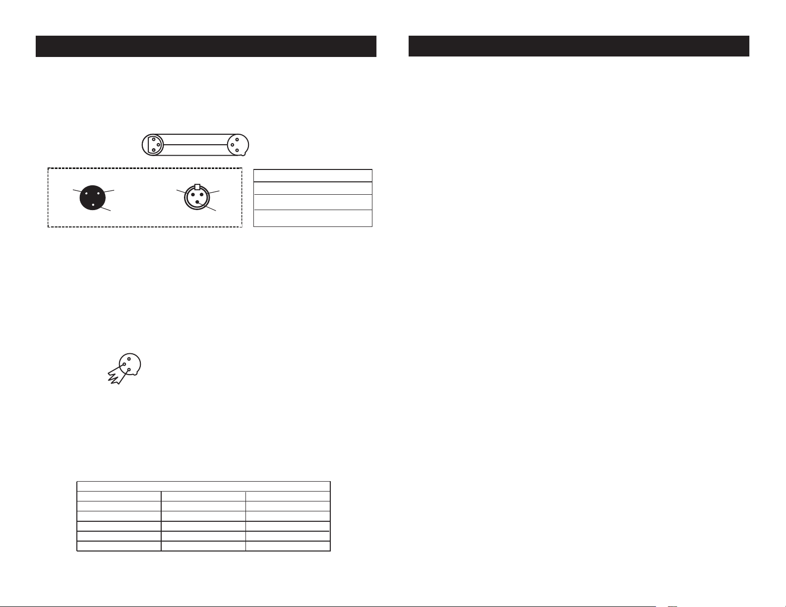
Data Cable (DMX Cable) Requirements (For DMX Operation):
The Penta Pix has 5 DMX Channel modes. The DMX address is set on the
rear panel of the Penta Pix. Your unit and your DMX controller require a
approved DMX-512 110 Ohm Data cable for data input and data output.
We recommend Accu-Cable DMX cables. If you are making your own
cables, be sure to use standard 110-120 Ohm shielded cable (This cable
may be purchased at almost all professional
sound and lighting stores). Your cables should be
made with a male and female XLR connector on
either end of the cable. Also remember that DMX
cable must be daisy chained and cannot be split.
Penta Pix Set Up
Figure 1

ADJ Products, LLC - www.adj.com - Penta Pix Instruction Manual Page 7
Penta Pix System Menu
The LCD backlight will shut o after 30 seconds, to relight
the background, press the MODE button for 5 seconds.
DMX Addr - Set the DMX Address Mode -
1. Press the MODE button until “DMX Addr” is displayed, press
ENTER.
2. The address will now begin to ash, use the UP and DOWN
buttons to nd your desired DMX address, then press ENTER.
DMX Mode - Set the DMX Channel Mode -
1. Press the MODE button until “DMX Mode” is displayed, and
press ENTER.
2. The current DMX channel mode will now begin to ash, use
the UP and DOWN buttons to nd your desired DMX Channel
mode, then press ENTER.
Slave Mode - This will let you set your unit as a slave in
a master/slave conguration.
1. Press the MODE button until “Slave Mode” is displayed. Your
unit will now follow the Master.
Static Color Mode - In this mode you can set a static
color.
1. Press the MODE button until “STATC” is displayed, and press
ENTER.
2. The “01” will now begin to ash. Press ENTER again and use
the UP and DOWN buttons to cycle through the various static
colors.
Dream Mode - This mode is a individual fade mode with
each lens generating a different color.
1. Press the MODE button until “STATC” is displayed, and press
ADJ Products, LLC - www.adj.com - Penta Pix Instruction Manual Page 6
Notice: Be sure to follow gures two and three when making your own
cables. Do not use the ground lug on the XLR connector. Do not con-
nect the cable’s shield conductor to the ground lug or allow the shield
conductor to come in contact with the XLR’s outer casing. Grounding
the shield could cause a short circuit and erratic behavior.
DMX512 IN
3-PIN XLR
SOUND
REMOTE
CONTROL
INPUT
POWER
INPUT OUTPUT
SOUND
REMOTE
CONTROL
INPUT
POWER
INPUT OUTPUT
SOUND
REMOTE
CONTROL
INPUT
POWER
INPUT OUTPUT
DMX512
DMX+,DMX-,COMMON
1
2
3
Termination reduces signal errors and
avoids signal transmission problems
and interference. It is always advisable
to connect a DMX terminal, (Resistance
120 Ohm 1/4 W) between PIN 2 (DMX-)
and PIN 3 (DMX +) of the last fixture.
1
2
3
1
2
3
DMX +
DMX -
COMMON
DMX512 OT
3-PIN XLR
Figure 2
Figure 3
1 Ground 1 Ground
XLR Male Socket
XLR Pin Conguration
3 Hot
2 Cold 2 Cold
3 Hot
XLR Female Socket
Pin 3 = Data True (positive)
Pin 2 = Data Compliment (negative)
Pin 1 = Ground
Special Note: Line Termination.
When longer runs of cable are
used, you may need to use a terminator on the last unit to avoid erratic
behavior. A terminator is a 110-120 ohm 1/4 watt resistor which is con-
nected between pins 2 and 3 of a male XLR connector (DATA + and
DATA -). This unit is inserted in the female XLR connector of the last
unit in your daisy chain to terminate the line. Using a cable terminator
(ADJ part number Z-DMX/T) will decrease the possibilities of erratic
behavior.
DMX512 IN
3-PIN XLR
SOUND
REMOTE
CONTROL
INPUT
POWER
INPUT OUTPUT
SOUND
REMOTE
CONTROL
INPUT
POWER
INPUT OUTPUT
SOUND
REMOTE
CONTROL
INPUT
POWER
INPUT OUTPUT
DMX512
DMX+,DMX-,COMMON
1
2
3
Termination reduces signal errors and
avoids signal transmission problems
and interference. It is always advisable
to connect a DMX terminal, (Resistance
120 Ohm 1/4 W) between PIN 2 (DMX-)
and PIN 3 (DMX +) of the last fixture.
1
2
3
1
2
3
DMX +
DMX -
COMMON
DMX512 OT
3-PIN XLR
Figure 4
5-Pin XLR DMX Connectors.
Some manufactures use 5-pin DMX-
512 data cables for DATA transmission in place of 3-pin. 5-pin DMX
xtures may be implemented in a 3-pin DMX line. When inserting stan-
dard 5-pin data cables in to a 3-pin line a cable adaptor must be used,
these adaptors are readily available at most electric stores. The chart
below details a proper cable conversion.
Conductor 5-Pin XLR Male (In)3-Pin XLR Female (Out)
Pin 1
Do Not Use
Do Not Use
Pin 3
Pin 2
Pin 1
Pin 3
Pin 2
Not Used
Not Used
Data True (+ signal)
Data Compliment (- signal)
Ground/Shield
3-Pin XLR to 5-Pin XLR Conversion
Penta Pix Set Up

ADJ Products, LLC - www.adj.com - Penta Pix Instruction Manual Page 9ADJ Products, LLC - www.adj.com - Penta Pix Instruction Manual Page 8
ENTER.
2. The “01” will now begin to ash. Press the UP or DOWN but-
tons so that “DREAM” is displayed.
2. You can change the speed of this mode by pressing ENTER
once more so that “SPXX” is now ashing. “XX” represents the
current speed setting. Use the UP and DOWN buttons to adjust
the speed.
Metor Mode - This mode is a individual color change
mode with each lens generating a different color.
1. Press the MODE button until “STATC” is displayed, and press
ENTER.
2. The “01” will now begin to ash. Press the UP or DOWN but-
tons so that “METOR” is displayed.
2. You can change the speed of this mode by pressing ENTER
once more so that “SPXX” is now ashing. “XX” represents the
current speed setting. Use the UP and DOWN buttons to adjust
the speed.
Color Fade Mode - This is a color fade mode with
each lens fading through the same colors.
1. Press the MODE button until “STATC” is displayed, and press
ENTER.
2. The “01” will now begin to ash. Press the UP or DOWN but-
tons so that “FADE” is displayed.
2. You can change the speed of this mode by pressing ENTER
once more so that “SPXX” is now ashing. “XX” represents the
current speed setting. Use the UP and DOWN buttons to adjust
the speed.
Penta Pix System Menu
Color Change Mode - This is a color change mode
with each lens color changing through the same colors.
1. Press the MODE button until “STATC” is displayed, and press
ENTER.
2. The “01” will now begin to ash. Press the UP or DOWN but-
tons so that “CHANG” is displayed.
2. You can change the speed of this mode by pressing ENTER
once more so that “SPXX” is now ashing. “XX” represents the
current speed setting. Use the UP and DOWN buttons to adjust
the speed.
Dim Curve - This setting will let you select your desired
dimming curve. See the chart on page 17 for more informa-
tion.
1. Press the MODE button until “Dim Curve” is displayed, press
ENTER.
2. 1 of 5 dimming curve settings will be displayed: Standard,
Stage, TV, Architectural, or Theatre. Use the UP and DOWN but-
tons to select your desired dimming curve and press ENTER to
conrm.
Manual Color Mode - In this mode you can adjust the
RGBW colors to make your own desired color.
1. Plug the fixture in and press the MODE button until
“MANUAL” is displayed.
2. When “R: XXX” is displayed you are in Red dimming mode.
Press the UP and DOWN buttons to adjust intensity. After you
have finished adjusting the intensity, or if you would like to skip
to the next color, press the ENTER button.
3. When “G: XXX” is displayed you are in Green dimming
mode. Press the UP and DOWN buttons to adjust intensity.
Penta Pix System Menu
Other manuals for penta pix
1
Table of contents
Other ADJ Dj Equipment manuals

ADJ
ADJ 32 HEX PANEL IP User manual

ADJ
ADJ Par Z100 3K User manual

ADJ
ADJ VF FLURRY User manual

ADJ
ADJ ikon profile ww User manual

ADJ
ADJ Dotz Par User manual

ADJ
ADJ Encore Profile 1000 WW User manual

ADJ
ADJ VIZI CMY300 User manual

ADJ
ADJ ENCORE FR50Z User manual

ADJ
ADJ Hydro Profile User manual

ADJ
ADJ INNO POCKET ROLL User manual

ADJ
ADJ DMX OPERATOR 384 User manual

ADJ
ADJ WOLFMIX WMX1 User manual

ADJ
ADJ Vizi Beam Hybrid 2R User manual

ADJ
ADJ POCKET PRO User manual

ADJ
ADJ HEX700 User manual

ADJ
ADJ UV LED BAR20 IR User manual

ADJ
ADJ MIRAGE Q6 PAK User manual

ADJ
ADJ Startec RAYZER User manual

ADJ
ADJ ELEMENT QA User manual

ADJ
ADJ UB 12H User manual