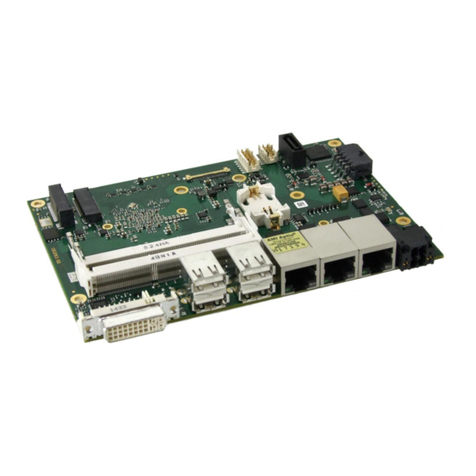
ADL Embedded Solutions ADLE3800HDC User manual

ADL Embedded Solutions GmbH, Eiserfelder Str. 316, ADL Embedded Solutions Inc. 4411 Morena Blvd., Suite 101
57080 Siegen, Germany San Diego, CA 92117-4345
P. +49 (0) 271 250 810 0 F. +49 (0) 271 250 810 20 P. +1 858 490-0597 F. +1 858 490-0599
e-mail: sales@adl-europe.com; web: http://www.adl-europe.com e-mail: sales@adl-usa.com; web: http://www.adl-usa.com
ADLE3800HDC
Manual
rev. 0.2


Contents
ADL Embedded Solutions ADLE3800HDC page 3
Contents
0Document History................................................................................................................................. 6
1Introduction .......................................................................................................................................... 7
1.1 Important Notes ............................................................................................................................ 7
1.2 Technical Support......................................................................................................................... 7
1.3 Warranty ....................................................................................................................................... 7
1.4 Return Authorization..................................................................................................................... 7
1.5 Description of Safety Symbols...................................................................................................... 8
1.6 RoHS ............................................................................................................................................ 8
1.7 FCC Approval for Canada ............................................................................................................ 8
1.8FCC Approvals for the United States of America......................................................................... 8
2Overview.............................................................................................................................................. 9
2.1 Features........................................................................................................................................ 9
2.2 Feature List................................................................................................................................. 10
2.3 Specifications and Documents ................................................................................................... 11
3Detailed Description........................................................................................................................... 12
3.1 Power Supply / UPS ................................................................................................................... 12
3.2 SUPS.......................................................................................................................................... 12
3.3 CPU ............................................................................................................................................ 12
3.4 Memory....................................................................................................................................... 12
3.5 M.2.............................................................................................................................................. 12
4Connectors......................................................................................................................................... 13
4.1 Connector Map ........................................................................................................................... 14
4.2 Power Supply.............................................................................................................................. 15
4.2.1 Mainboard Power Supply.................................................................................................... 15
4.2.2 Power Supply for Peripherals (I-PEX) ................................................................................ 16
4.2.3 Power Supply for Peripherals (SATA) ................................................................................ 17
4.2.4 S-UPS................................................................................................................................. 18
4.2.5 External CMOS Battery ...................................................................................................... 19
4.3 Front Panel Connectors.............................................................................................................. 20
4.3.1 DVI / HDMI / VGA............................................................................................................... 20
4.3.2 USB..................................................................................................................................... 22
4.3.3 LAN..................................................................................................................................... 23
4.4 Internal Connectors .................................................................................................................... 24
4.4.1 Memory............................................................................................................................... 24
4.4.2 M.2 2280 (Keying B)........................................................................................................... 27
4.4.3 M.2 2242 (Keying B)........................................................................................................... 29
4.4.4 DVI/HDMI/DisplayPort and USB3.0.................................................................................... 31
4.4.5 SATA Interface.................................................................................................................... 33
5BIOS Settings..................................................................................................................................... 34
5.1 General Remarks........................................................................................................................ 34
5.2 Main............................................................................................................................................ 35
5.3 Advanced.................................................................................................................................... 36
5.3.1 ACPI Settings...................................................................................................................... 38
5.3.2 H/W Monitor........................................................................................................................ 39
5.3.3 CPU Configuration.............................................................................................................. 40
5.3.4 PPM Configuration.............................................................................................................. 43

Contents
page 4 ADL Embedded Solutions ADLE3800HDC
5.3.5 SATA Configuration............................................................................................................ 44
5.3.6 Miscellaneous Configuration............................................................................................... 45
5.3.7 Network Stack..................................................................................................................... 46
5.3.8 Power Controller Options.................................................................................................... 47
5.3.9 CSM Configuration ............................................................................................................. 48
5.3.10 Advanced-Menü-NVMe Configuration................................................................................ 49
5.3.11 SDIO Configuration............................................................................................................. 50
5.3.12 USB Configuration.............................................................................................................. 51
5.3.13 Security Configuration ........................................................................................................ 52
5.3.14 Intel(R) I210 Gigabit Network Connection.......................................................................... 53
5.3.15 Driver Health....................................................................................................................... 55
5.4 Chipset........................................................................................................................................ 57
5.4.1 North Bridge........................................................................................................................ 58
5.4.2 South Bridge....................................................................................................................... 62
5.5 Security....................................................................................................................................... 66
5.5.1 Secure Boot menu.............................................................................................................. 67
5.6 Boot............................................................................................................................................. 69
5.6.1 Advanced Fixed Boot Order Parameters............................................................................ 70
5.7 Save & Exit ................................................................................................................................. 71
5.8 BIOS-Update .............................................................................................................................. 72
6Mechanical Drawings......................................................................................................................... 73
6.1 PCB: Mounting Holes ................................................................................................................. 73
6.2 PCB: Die Center ......................................................................................................................... 74
6.3 PCB: Pin 1 Dimensions .............................................................................................................. 75
6.4 PCB: Outlines ............................................................................................................................. 76
6.5 Heat Spreader: Chassis Mount................................................................................................... 77
7Technical Data................................................................................................................................... 78
7.1 Electrical Data............................................................................................................................. 78
7.2 Environmental Conditions........................................................................................................... 78
7.3 Thermal Specifications ............................................................................................................... 79
IAnnex: Post-Codes............................................................................................................................ 81
II Annex: Resources.............................................................................................................................. 82
IO Range................................................................................................................................................ 82
Memory-Bereich..................................................................................................................................... 82
Interrupt.................................................................................................................................................. 82
PCI Devices............................................................................................................................................ 83
SMB Devices.......................................................................................................................................... 83

Important Notes Chapter: Document History
ADL Embedded Solutions ADLE3800HDC page 5

Chapter: Document History Important Notes
page 6 ADL Embedded Solutions ADLE3800HDC
0 Document History
Version
Changes
0.1
first pre-release
0.2
updated BIOS chapter
All company names, brand names, and product names referred to in this manual are registered or
unregistered trademarks of their respective holders and are, as such, protected by national and
international law.

Important Notes Chapter: Introduction
ADL Embedded Solutions ADLE3800HDC page 7
1 Introduction
1.1 Important Notes
Please read this manual carefully before you begin installation of this hardware device. To avoid
Electrostatic Discharge (ESD) or transient voltage damage to the board, adhere to the following rules at
all times:
oYou must discharge your body from electricity before touching this board.
oTools you use must be discharged from electricity as well.
oPlease ensure that neither the board you want to install, nor the unit on which you want to install this
board, is energized before installation is completed.
oPlease do not touch any devices or components on the board.
As soon as the board is connected to a working power supply, touching
the board may result in electrical shock, even if the board has not been
switched on yet. Please also note that the mounting holes for heat sinks
are connected to ground, so when using an externally AC powered device, a substantial ground
plane differential can occur if the external device's AC power supply or cable does not include an
earth ground. This could also result in electrical shock when touching the device and the heat sink
simultaneously.
1.2 Technical Support
Technical support for this product can be obtained in the following ways:
oBy contacting our support staff at +1 858-490-0597 or +49 (0) 271 250 810 0
oBy contacting our staff via e-mail at support@adl-usa.com or support@adl-europe.com
oVia our website at www.adl-usa.com/support or www.adl-europe.com/support
1.3 Warranty
This product is warranted to be free of defects in workmanship and material. ADL Embedded Solutions'
sole obligation under this warranty is to provide replacement parts or repair services at no charge, except
shipping cost. Such defects which appear within 12 months of original shipment of ADL Embedded
Solutions will be covered, provided a written claim for service under warranty is received by ADL
Embedded Solutions no less then 30 days prior to the end of the warranty period of within 30 days of
discovery of the defect –whichever comes first. Warranty coverage is contingent upon proper handling
and operation of the product. Improper use such as unauthorized modifications or repair, operation
outside of specified ratings, or physical damage may void any service claims under warranty.
1.4 Return Authorization
All equipment returned to ADL Embedded Solutions for evaluation, repair, credit return, modification, or
any other reason must be accompanied by a Return Material Authorization (RMA) number. ADL
Embedded Solutions requires a completed RMA request form to be submitted in order to issue an RMA
number. The form can be found under the Support section at our website: www.adl-usa.com or www.adl-
europe.com. Submit the completed form to support@adl-usa.com or fax to +1 858-490-0599 for the USA
office, or to rm[email protected] or fax to +49 (0) 271 250 810 20 to request an RMA from the European
office in Germany. Following a review of the information provided, ADL Embedded Solutions will issue an
RMA number.
WARNING

Chapter: Introduction Description of Safety Symbols
page 8 ADL Embedded Solutions ADLE3800HDC
1.5 Description of Safety Symbols
The following safety symbols are used in this documentation. They are intended to alert the reader to the
associated safety instructions.
DANGER indicates a hazardous situation which, if not avoided, will result
in death or serious injury.
WARNING indicates a hazardous situation which, if not avoided, could
result in death or serious injury.
CAUTION indicates a hazardous situation which, if not avoided, could
result in minor or moderate injury.
NOTICE is used to address practices not related to physical injury.
1.6 RoHS
The PCB and all components are RoHS compliant (RoHS = Restriction of Hazardous Substances
Directive). The soldering process is lead free.
1.7 FCC Approval for Canada
FCC: Canadian Notice
This equipment does not exceed the Class A limits for radiated emissions as described in the Radio
Interference Regulations of the Canadian Department of Communications.
1.8 FCC Approvals for the United States of America
FCC: Federal Communications Commission Radio Frequency Interference Statement
This equipment has been tested and found to comply with the limits for a Class A digital device, pursuant
to Part 15 of the FCC Rules. These limits are designed to provide reasonable protection against harmful
interference when the equipment is operated in a commercial environment. This equipment generates,
uses, and can radiate radio frequency energy and, if not installed and used in accordance with the
instruction manual, may cause harmful interference to radio communications. Operation of this equipment
in a residential area is likely to cause harmful interference in which case the user will be required to
correct the interference at his own expense.
DANGER
WARNING
CAUTION
NOTICE

Features Chapter: Overview
ADL Embedded Solutions ADLE3800HDC page 9
2 Overview
2.1 Features
The ADLE3800HDC is a highly complex 3,5-inch board which incorporates complete motherboard
functionality. It's based on a System-On-Chip (SoC) of Intel®'s Atom E3800 product family. Modern low
voltage DDR3L technology provides top-notch memory performance, accomodating up to 16 GByte of
RAM (DDR3L-1333) via SO-DIMM204.
The frontpanel provides standard interfaces, such as a DVI/HDMI/DisplayPort connector, 3 Gigabit LAN
interfaces and 4 USB2.0 interfaces.
The ADLE3800HDC also provides internal interfaces, such as an 30pin I-PEX connector, which makes
DVI/HDMI/DP signals and a USB3.0 interface available, a SATA connector and two M.2(B) sockets,
which make PCI Express (1 x PCIe x1) and SATA signals available.
The power supply is realized via a 4pin connector. For connected peripherals, such as a display or a
SSD, the ADLE3800HDC provides two additional power supplies via internal FCI connectors.
Input voltage is 24V.
Intel® Atom™
E3840, E3823
1x
SoDIMM204
DDR3L-
1333
MEMORY
Power VCCCore;
DDRVTT; GFXVCC;
1.05V; 1.5V; 1.8V; 3.3V BIOS
SATA1-2
USB2-9
CRT
1.5GB/3.0GB
Intel®
i210
LAN1-3 10/100/
1000
SMBus
SPI
USB 2.0
NXP®
PCA9535
SMBus 8x GPIO
SMSC®
SCH3114
LPC
MS
KB
COM1
FAN 1-3
DVI/HDMI
DVI/HDMI/DP
(I-PEX)
1 x PCIe x1
USB 3.0
USB1
(I-PEX)

Chapter: Overview Feature List
page 10 ADL Embedded Solutions ADLE3800HDC
2.2 Feature List
ADLE3800HDC
3,5"-Board
CPU
Atom™ E3845 (QC, 2M, 1.91 GHz), TDP 10W
Atom™ E3827 (DC, 1M, 1.75 GHz), TDP 8W
Atom™ E3826 (DC, 1M, 1.46 GHz), TDP 7W
Atom™ E3825 (DC, 1M, 1.33 GHz), TDP 6W
Atom™ E3815 (SC, 1M, 1.46 GHz), TDP 5W
Memory
Variants with Intel® Atom™ E3815 oder E3825: 1 socket with
DDR3L@1066/1333MHz à 8GB
Variants with Intel® Atom™ E3826, E3827 or E3845: 2 sockets,
each with 1x DDR3L @ 1066/1333MHz à 8GB (up to 16GB total
memory)
I/O
1 x SATA 2.0
1 x I-PEX
1 x M.2(B) Typ 2242 for SSD connection (SATA)
1 x M.2(B) Typ 2280 for PCIe connection
4 x USB 2.0
3 x GBit-LAN, Intel® i210
1 x DVI-I (DVI / HDMI / DP)
Graphics
HDMI / DVI: 1920 x 1200 (at 16:10), 1920 x 1600 (at 16:9)
DP / eDP: 2560 x 1600 (at 16:10), 2560 x 1440 (at 16:9)
RTC
changeable horizontal onboard battery
BIOS
AMI® Aptio V
Power Supply
16V - 36V input voltage range
Over- and undervoltage protection
S-UPS connection
Reverse voltage protection
not galvanically isolated
Format
102 mm x 147 mm

Specifications and Documents Chapter: Overview
ADL Embedded Solutions ADLE3800HDC page 11
2.3 Specifications and Documents
In making this manual and for further reading of technical documentation, the following documents,
specifications and web-pages were used and are recommended.
PCI specification
Version 2.3 bzw. 3.0
www.pcisig.com
PCI Express® Base specification
Version 2.0
www.pcisig.com
ACPI specification
Version 3.0
www.acpi.info
ATA/ATAPI specification
Version 7 Rev. 1
www.t13.org
USB specifications
www.usb.org
SM-Bus specification
Version 2.0
www.smbus.org
Intel® Chip Description
Intel® Atom™ Processor E3800 Product Family datasheet
www.intel.com
Intel® Chip Description
i210 Datasheet
www.intel.com
SMSC® Chip Description
SCH3114 Datasheet
www.smsc.com
(NDA required)
American Megatrends®
Aptio™ Text Setup Environment (TSE) User Manual
www.ami.com
American Megatrends®
Aptio™ 4.x Status Codes
www.ami.com

Chapter: Detailed Description Power Supply / UPS
page 12 ADL Embedded Solutions ADLE3800HDC
3 Detailed Description
3.1 Power Supply / UPS
The ADLE3800HDC needs an external power supply of 24V (will tolerate 20V-30V). This input is
galvanically isolated from the board's internal circuitry. It is also used for charging any UPS device that
may be present. This UPS device is either capacitor-based or connected externally as a Pb-battery pack.
With a UPS installed and charged, the module can stay operational even when a power failure occurs. A
capacitor-based UPS can keep the board alive only for a few seconds while a Pb-battery typically allows
for several minutes of continued operation. The exact amount of time is hard to predict as it also depends
on factors such as the UPS' charge level at the time of the power failure, CPU/chipset power consumption
etc. Generally, a Pb-battery needs a much longer time to reach full charge level compared to a capacitor-
based UPS.
3.2 SUPS
Optionally the ADLE3800HDC can be equipped with a plug-in SUPS, which can keep the board alive over
a short period of time in case of power failure or voltage fluctuation. The exact amount of time is hard to
predict as it also depends on factors such as the SUPS' capacitors and the boards' power consumption
etc. The capacitors size is only limited by the required space.
3.3 CPU
The motherboard employs an Intel® Atom™ processor of the E3800 family, which is a system-on-chip
(SoC) being optimized for low power consumption while at the same time providing state-of-the-art
computing performance.
The processors include a second level cache of 512 KByte. They also offer many features known from
the desktop range such as MMX2, serial number, loadable microcode etc.
The Atom™ CPU operates in an extended range of thermal conditions and therefore is capable for use in
industrial systems.
3.4 Memory
The ADLE3800HDC is equipped with two SO-DIMM204 sockets for DDR3L-1333-RAM. For technical and
mechanical reasons it is possible that particular memory modules cannot be employed. Please ask your
distributor for recommended memory modules.
With currently available SO-DIMM204 modules a memory extension up to 16 GByte is possible -
depending on the variants components. Product variants with Intel® Atom processors E3815 or E3825
provide only one memory socket. Therefore with those variants a memory extension is possible only up to
8 GByte.
If both memory sockets are in use, notice that you must use identical memory modules.
Please notice, that if only one memory socket shall be used, this one must be the memory socket U500
(which is the lower one).
3.5 M.2
M.2 is a PCIe based standard. With it's four PCI Express lanes and a SATA port it allows a great I/O
flexibility. SSDs can reach a higher speed, which is no longer limited by the SATA interface. Therefore the
M.2 standard enables the use of various PCBs and customized SATA/PCIe cards.
The ADLE3800HDC offers two M.2 sockets (both with keying B). The M.2-2280 socket provides PCI
Express signals (1x PCIe x1), the M.2-2242 socket provides SATA signals and enables the connection of
SSD cards.
For optimal driver compatibility we recommend the use of a Microsoft®
Windows® 8 operating system.
NOTICE

M.2 Chapter: Connectors
ADL Embedded Solutions ADLE3800HDC page 13
4 Connectors
This section describes all the connectors found on the ADLE3800HDC.
Please consider the requirements on the cabling!
For most interfaces, the cables must meet certain requirements. For
instance, USB 2.0 requires twisted and shielded cables to reliably
maintain full speed data rates. Restrictions on maximum cable length are also in place for many
high speed interfaces and for power supply. Please refer to the respective specifications and use
suitable cables at all times.
NOTICE

Chapter: Connectors Connector Map
page 14 ADL Embedded Solutions ADLE3800HDC
4.1 Connector Map
Please use the connector map below for quick reference. Only connectors on the component side are
shown. For more information on each connector refer to the table below.
Ref.-No.
Function
Page
U500/501
"Memory"
p. 24
P1000
"M.2 2280 (Keying B)"
p. 27
P1001
"M.2 2242 (Keying B)"
p. 29
P1002
"Power Supply for Peripherals (I-PEX)"
p. 16
P1003
"Power Supply for Peripherals (SATA)"
p. 17
P1004
"DVI/HDMI/DisplayPort and USB3.0"
p. 31
P1005
"SATA Interface"
p. 33
P1006
"S-UPS"
p. 18
P1100/2/4
"LAN"
p. 23
P1101/3
"USB"
p. 22
P1105
"DVI / HDMI / VGA"
p. 20
P1106
"Mainboard Power Supply"
p. 15

Power Supply Chapter: Connectors
ADL Embedded Solutions ADLE3800HDC page 15
4.2 Power Supply
4.2.1 Mainboard Power Supply
The power supply of the ADLE3800HDC is realized via a 2x2pin connector (P20THR-1787014). The main
24V power lines are assigned to pin 3.
If a UPS is present you need to have a possibility to shut down the board in a regular way without
activating the UPS, thereby preventing premature aging of UPS components. That's what pin 1
(PC_START) is for. When pulled high (24V) a regular shutdown without UPS activity is triggered. As a
part of this regular shutdown pin 2 (PC_AKTIV) is pulled from 24V to 0V.
Manufacturer
Description
Mating Connector
Phoenix
P20THR-1787014
DFMC 1,5/ 2-ST-3,5-LR- 1790292
Description
Name
Pin
Name
Description
PC Start
PC_START
1
2
PC_AKTIV
PC Status
Power Supply 24V
Vin
3
3
GND
Ground

Chapter: Connectors Power Supply
page 16 ADL Embedded Solutions ADLE3800HDC
4.2.2 Power Supply for Peripherals (I-PEX)
The ADLE3800HDC has a 2x6pin connector, which provides the power supply for displays, which are
connected via I-PEX.
Maximum current is 6 amperes for VCC combined (2A per contact), and also 6 amperes for 12V (2A per
contact).
Manufacturer
Description
Mating Connector
FCI
FCI 98424-G52-12LF
FCI 90311-012LF
Pinout power connector 2x6:
Description
Name
Pin
Name
Description
power supply 5V
VCC
1
7
VCC
power supply 5V
power supply 5V
VCC
2
8
GND
ground
ground
GND
3
9
GND
ground
ground
GND
4
10
GND
ground
power supply 12V
12V
5
11
GND
ground
power supply 12V
12V
6
12
12V
power supply 12V

Power Supply Chapter: Connectors
ADL Embedded Solutions ADLE3800HDC page 17
4.2.3 Power Supply for Peripherals (SATA)
The ADLE3800HDC has a 2x4pin connector, which provides the power supply for devices, which are
connected via SATA.
Maximum current is 2 amperes for VCC combined (2A per contact), and also 2 amperes for 12V and 3,3V
(2A per contact).
Manufacturer
Description
Mating Connector
FCI
98424-G52-08LF
90311-008LF
Pinout power connector 2x4:
Description
Name
Pin
Name
Description
battery (Input)
BATT_E
1
5
GND
ground
power supply 3,3V
3,3V
2
6
GND
ground
power supply
VCC
3
7
GND
ground
power supply
12V
4
8
GND
ground

Chapter: Connectors Power Supply
page 18 ADL Embedded Solutions ADLE3800HDC
4.2.4 S-UPS
A S-UPS module can be connected to the ADLE3800HDC via a 2x5pin connector. The S-UPS is able to
maintain the power supply for the ADLE3800HDC for a few seconds, depending on the capacity and
power consumption.
Manufacturer
Description
Mating Connector
Molex
43045-1009
Molex 43025-1009
Pinout Molex 2x5:
Description
Name
Pin
Name
Description
output voltage
Voutreg
1
6
Voutreg
output voltage
output voltage
Vout
2
7
Vout
output voltage
ground
GND
3
8
GND
ground
SUSV
SUSV
4
9
SMBALERT#
SMB alert
SMB data
SMB-DAT
5
10
SMB-CLK
SMB clock

Power Supply Chapter: Connectors
ADL Embedded Solutions ADLE3800HDC page 19
4.2.5 External CMOS Battery
The board ships with a CR2032 battery holder (Renata VBH2032-1) and 3V battery.

Chapter: Connectors Front Panel Connectors
page 20 ADL Embedded Solutions ADLE3800HDC
4.3 Front Panel Connectors
A range of standard connectors are available: You can connect displays, USB, LAN etc. The following
connectors are located on the front-panel of the ADLE3800HDC.
4.3.1 DVI / HDMI / VGA
The ADLE3800HDC is connected to an external display via a DVI-I connector, which supports analog and
digital displays. A HDMI display can be connected.
Manufacturer
Description
Mating Connector
Molex
74320-9010
standard DVI connector
Pinout DVI-I:
Pin
Name
Description
1
TMDSDAT2#
DVI data 2 -
2
TMDSDAT2
DVI data 2 +
3
GND
ground
4
N/C
reserved
5
N/C
reserved
6
DDC CLK
DDC clock (DVI/VGA)
7
DDC DAT
DDC data (DVI/VGA)
8
VSYNC
VGA vertical synchronization
9
TMDSDAT1#
DVI data 1 -
10
TMDSDAT1
DVI data 1 +
11
GND
ground
12
N/C
reserved
13
N/C
reserved
14
VCC
5 volt supply
15
GND
ground
16
HP_DETECT
hot plug detect
17
TMDSDAT0#
DVI data 0 -
18
TMDSDAT0
DVI data 0 +
19
GND
ground
20
N/C
reserved
21
N/C
reserved
22
GND
ground
Table of contents
Other ADL Embedded Solutions Motherboard manuals
