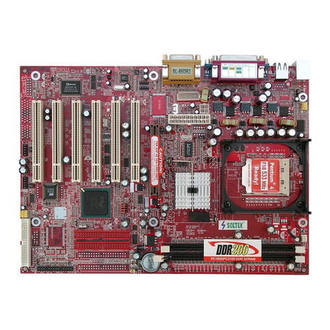
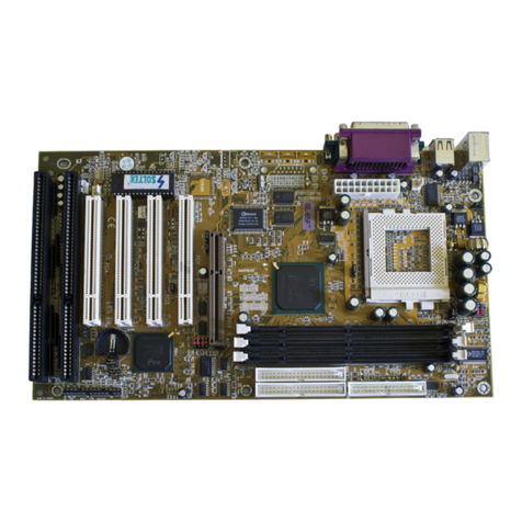
SOLTEK SL-855GEI-FDGR User manual

5
SL-855GEI-FDGR Chapter 1 Specification and Hardware
BIOS
USB1
1
DDR 333/266MHz
VIA
VT6307
CD-IN1
1
Battery
Li
DIMM1
PW1
PW2
850
ALC
Fan2
SATA1
+12V Power
1
JAUD1
CLOSED OPEN
DIMM2
AGP1 4X
PCI1
PCI3
PCI2
IDE2
1
IDE1
1
1
FD1
Main Power
Fan3
Fan1
SATA2
1
SJP1
NJP1
HD IR PWR
SPK RST
PLED
1
Promise
PDC20579
RTL
8110SB
RTL
8110SB
ITE
8712F
LED1
855GME
Intel
ICH4
Intel
1JBAT1
1JKB1
LJP1
LJP2
COM2
LPT1
1
1
IEEE1
1
IEEE2
SPDIF
Out
SPDIF
In
PS/2 Keyboard
COM1
LineOut/ Front SpeakerOut
LineIn
Mic In
PS/2
Mouse
VGA
2 USB Ports
RJ45
RJ45
Linein
(ontop)
SideSpeakerOut
Center/SubwooferOut
Rear
Speaker
2 USB Ports
RT2
RT1
CN1
CN2
1
1-1 Mainboard Components Layout
Chapter 1 Specification
for
CRT Monitor
10/100/1KMb
LAN connector
10/100/1KMb
LAN connector
DVO/AGP4X
CD-ROM
Audio-out
connector
2xIEEE 1394A
connectors
Front Audio
Connector
CPU Temperature
Detector
(Dedicated)
CPU Fan Connector Sys. Temperature
Detector
Printer Port
1
10
Black
+5V
Red GreenWhite GNDD2- D2+
Black
GND
Green
D1+
White
D1-+5V
Red
Use 1x4-pin connector to
support 1xUSB port only.
Use a 4-pin connector to connect
USB pin-header to 1 USB port
Serial Port
1st
2nd
or
SATA / RAID Connectors
USB pin-header (for 2 USB ports)
PLED-
NC
PLED+
RSTGND
RST1
SP1
NC
SP3
SPVCC
PWRBT#
PWRBT
IR_VCC
NC
IRRX
IRGND
IRTX
HDLED-
HDLED+
Front Panel Connectors
Intel 479-pin
CPU Socket
STR LED

6
SL-855GEI-FDGR Chapter 1 Specification and Hardware
1-2 Mainboard Specification Table
SL-855GEI-FDGR pecifications and Features
CPU
South Bridge
North Bridge
Socket 479 for Pentium M / Celeron M CPU,
400MHz FSB
ICH4
Intel 855GME , supporting DDR333/266MHz
Other features
I/O Connectors
PCI Slots
IDE Interface
Audio
AGP interface
I/O Chip
Memory
PS/2 Keyboard/Mouse Wake Up;
Suspend To RAM mode (STR/S3) supported;
IEEE 1394A interface integrated, 2x1394A ports
6 USB2.0 ports, 1 FDD port, 2 COM ports, 1 LPT,
1 IrDA, 1 PS/2 Keyboard, 1 PS/2 Mouse
3 PCI Master slots on board
2 UATA 66/100 IDE ports
AC’97 Audiio Codec ALC850, 8-channel audio;
1xSPDIF-out and 1xSPDIF-in integrated, for
SPDIF-in/out playback;
Supporting DDR 333/266 SDRAM, up to 2GB in
2 DIMM slots
ITE IT8712F
1 AGP 4XSlot on board ,for AGP card display
VGA VGA integrated
SATA / RAID
Interface SATA / RAID interface, supported by PDC20579,
with 2 SATA / RAID connectors integrated
LAN 2x Gigabit LAN controllers, 2 RJ45 connectors

7
SL-855GEI-FDGR Chapter 1 Specification and Hardware
1-3 CPU and Fan Installation with Socket 479
This series is built with CPU Socket 479 supporting the Intel CPUs
Pentium M / Celeron M.
1. To identify Intel 479-pin CPU
(no metal plate on top)
2. To identify Socket 479
Intel 479-pin CPU Pin 1 position
3. Insert CPU into Socket 479,
CPU Pin1 to Socket Pin1,
Fan Base
CPU Pin1 to Socket Pin1.
5. Install cooling fan
into Fan Base.
4. To identify a set of cooling
Fan with dedicated Heat
Sink for Intel 479-pin CPU.
2-layer Socket 479
Screw-lock:
(1) Turn the screw counter-clockwise
to open the 2-layer interlock.
(2) Turn the screw clockwise to close
the 2-layer interlock
Pin 1 position
Use a screw-driver to open/close Screw-lock:
(1) Turn the screw counter-clockwise to open
the 2-layer interlock for inserting CPU down.
(2) Turn the screw clockwise to close the 2-
layer interlock for locking CPU in.
screw driver
With Heat
Glue applied
herein Pin1 position
2 Spring Catches
cooling Fan Power Connector
Heat sink broad side
to Fan Base Catch Side
Catch Side
6.Hook up 2 Spring
Catches to Fan
Base.
7. Connect Fan Power
connector to CPU
Fan Power
Connector.
Heat Sink
Dedicated

8
SL-855GEI-FDGR Chapter 1 Specification and Hardware
BIOS
USB1
1
DDR 333/266MHz
VIA
VT6307
CD-IN1
1
Battery
Li
DIMM1
PW1
PW2
850
ALC
Fan2
SATA1
+12V Power
1
JAUD1
CLOSED OPEN
DIMM2
AGP1 4X
PCI1
PCI3
PCI2
IDE2
1
IDE1
1
1
FD1
Main Power
Fan3
Fan1
SATA2
1
SJP1
NJP1
HD IR PWR
SPK RST
PLED
1
Promise
PDC20579
RTL
8110SB
RTL
8110SB
ITE
8712F
LED1
855GME
Intel
ICH4
Intel
1JBAT1
1JKB1
LJP1
LJP2
COM2
LPT1
1
1
IEEE1
1
IEEE2
SPDIF
Out
SPDIF
In
PS/2 Keyboard
COM1
LineOut/FrontSpeakerOut
LineIn
MicIn
PS/2
Mouse
VGA
2 USB Ports
RJ45
RJ45
Linein
(ontop)
SideSpeakerOut
Center/SubwooferOut
Rear
Speaker
2 USB Ports
RT2
RT1
CN1
CN2
1
1-5 ATX V 2.03 Power Supply Installation
Main Power
Connector
+12V
5SB
PWR OK
GND GND
GND
GND
GND
GND
+5V
+5V
-5V
+5V
+5V
+3.3V
+3.3V
+3.3V
PS ON#
Pin1Pin11
-12V
GND
Warning: Both the Main
Power Connector and the
+12V Power Connector
should be connected to
Power Supply; otherwise,
the system may be dam-
aged or not start.
+12V Power Connector
GND
GND
+12V
+12V
12
34
BIOS
USB1
1
DDR 333/266MHz
VIA
VT6307
CD-IN1
1
Battery
Li
DIMM1
PW1
PW2
850
ALC
Fan2
SATA1
+12V Power
1
JAUD1
CLOSED OPEN
DIMM2
AGP1 4X
PCI1
PCI3
PCI2
IDE2
1
IDE1
1
1
FD1
Main Power
Fan3
Fan1
SATA2
1
SJP1
NJP1
HD IR PWR
SPK RST
PLED
1
Promise
PDC20579
RTL
8110SB
RTL
8110SB
ITE
8712F
LED1
855GME
Intel
ICH4
Intel
1JBAT1
1JKB1
LJP1
LJP2
COM2
LPT1
1
1
IEEE1
1
IEEE2
SPDIF
Out
SPDIF
In
PS/2 Keyboard
COM1
LineOut/FrontSpeakerOut
LineIn
MicIn
PS/2
Mouse
VGA
2 USB Ports
RJ45
RJ45
Linein
(on top)
SideSpeakerOut
Center/SubwooferOut
Rear
Speaker
2 USB Ports
RT2
RT1
CN1
CN2
1
GND
+12V
SENSOR
Void
+12V
GND
Sensor No
FAN2, sensor Fan
System / Device Fan
Connector
FAN1, Smart and Sensor
Dedicated CPU Fan
Connector
FAN3, Sensor Fan
System / Device Fan
Connector
1-4 On board Fan Connector Setup

9
SL-855GEI-FDGR Chapter 1 Specification and Hardware
BIOS
USB1
1
DDR 333/266MHz
VIA
VT6307
CD-IN1
1
Battery
Li
DIMM1
PW1
PW2
850
ALC
Fan2
SATA1
+12V Power
1
JAUD1
CLOSED OPEN
DIMM2
AGP1 4X
PCI1
PCI3
PCI2
IDE2
1
IDE1
1
1
FD1
Main Power
Fan3
Fan1
SATA2
1
SJP1
NJP1
HD IR PWR
SPK RST
PLED
1
Promise
PDC20579
RTL
8110SB
RTL
8110SB
ITE
8712F
LED1
855GME
Intel
ICH4
Intel
1JBAT1
1JKB1
LJP1
LJP2
COM2
LPT1
1
1
IEEE1
1
IEEE2
SPDIF
Out
SPDIF
In
PS/2 Keyboard
COM1
LineOut/FrontSpeakerOut
LineIn
MicIn
PS/2
Mouse
VGA
2 USB Ports
RJ45
RJ45
Linein
(ontop)
SideSpeakerOut
Center/SubwooferOut
Rear
Speaker
2 USB Ports
RT2
RT1
CN1
CN2
1
1. To install on-board VGA, please connect your CRT monitor directly
to VGA connector on board.
1-6 VGA / AGP 4X Slot Setup
2. To install AGP 4X display, please insert an AGP4X card into the AGP
slot.
VGA
Connector
Analog
Monitor
AGP Accelerator
4X notch
(1)Power Switch PLED-
NC
PLED+
RSTGND
RST1
SP1
NC
SP3
SPVCC
PWRBT#
PWRBT
IR_VCC
NC
IRRX
IRGND
IRTX
HDLED-
HDLED+
(2)Infrared(IR)
(3)HDD LED
Power LED (4)
Reset Switch (5)
Speaker (6)
Front Panel Connectors Illustration
1-7 Front Panel Connectors (Complex Header) Setup
This complex Header consists of 6 connectors providing various
supports:

10
SL-855GEI-FDGR Chapter 1 Specification and Hardware
1-8 Serial ATA/RAID Connectors Setup
The Serial ATA interface improves the Parallel ATA with the capability of
Hot Plug and offers a data bandwidth of 150Mbytes/second. It also re-
duces voltage and pin count.
2 Serial ATA connectors are built on board, supported by the SATA RAID
Controller for SATA / RAID Hard Disk Drives setup.
Serial ATA Connectors
Serial ATA
Hard Disk
Serial ATA
Cable
Serial ATA Power Cable
To Power
Supply
SATA Power
Connector
SATA1 SATA2
(optional)
BIOS
USB1
1
DDR 333/266MHz
VIA
VT6307
CD-IN1
1
Battery
Li
DIMM1
PW1
PW2
850
ALC
Fan2
SATA1
+12V Power
1
JAUD1
CLOSED OPEN
DIMM2
AGP1 4X
PCI1
PCI3
PCI2
IDE2
1
IDE1
1
1
FD1
Main Power
Fan3
Fan1
SATA2
1
SJP1
NJP1
HD IR PWR
SPK RST
PLED
1
Promise
PDC20579
RTL
8110SB
RTL
8110SB
ITE
8712F
LED1
855GME
Intel
ICH4
Intel
1JBAT1
1JKB1
LJP1
LJP2
COM2
LPT1
1
1
IEEE1
1
IEEE2
SPDIF
Out
SPDIF
In
PS/2 Keyboard
COM1
LineOut/FrontSpeakerOut
LineIn
MicIn
PS/2
Mouse
VGA
2 USB Ports
RJ45
RJ45
Linein
(ontop)
SideSpeakerOut
Center/SubwooferOut
Rear
Speaker
2 USB Ports
RT2
RT1
CN1
CN2
1
RAID Controller
Select
1-2 closed
(default)
2-3 closed
SJP1:
1
1
RAID enabled
RAID disabled
SATA RAID
Controller

11
SL-855GEI-FDGR Chapter 1 Specification and Hardware
BIOS
USB1
1
DDR 333/266MHz
VIA
VT6307
CD-IN1
1
Battery
Li
DIMM1
PW1
PW2
850
ALC
Fan2
SATA1
+12V Power
1
JAUD1
CLOSED OPEN
DIMM2
AGP1 4X
PCI1
PCI3
PCI2
IDE2
1
IDE1
1
1
FD1
Main Power
Fan3
Fan1
SATA2
1
SJP1
NJP1
HD IR PWR
SPK RST
PLED
1
Promise
PDC20579
RTL
8110SB
RTL
8110SB
ITE
8712F
LED1
855GME
Intel
ICH4
Intel
1JBAT1
1JKB1
LJP1
LJP2
COM2
LPT1
1
1
IEEE1
1
IEEE2
SPDIF
Out
SPDIF
In
PS/2 Keyboard
COM1
LineOut/FrontSpeakerOut
LineIn
MicIn
PS/2
Mouse
VGA
2 USB Ports
RJ45
RJ45
Linein
(ontop)
SideSpeakerOut
Center/SubwooferOut
Rear
Speaker
2 USB Ports
RT2
RT1
CN1
CN2
1
JAUD1
External Audio Connector
This Mainboard is designed with a Front Panel Audio connector “JAUD1”
which provides connection to your chassis.
1. When JAUD1 is set to 5-6 closed and 9-10 closed, this default setting
disables this connector and leaves the Back Panel Audio enabled.
2. To use this Front Panel Audio Connector, please open all pins of
JAUD1 and connect it to your chassis.
1-9 Front Audio Connector Setup
1-10 Suspend-to-RAM LED
LED1 is designed as a Suspend-to-RAM LED which will light up when
the running system is suspended to RAM (STR or S3) mode.
To enable S3 mode, please enter BIOS Setup, then Power Manage-
ment Setup, and then select S3 choice for the ACPI Suspend Type.
Thereafter, when you select “Suspend” instead of “Turn Off” during
turning off your running system, your system will be suspended to
RAM instead of totally being shut down. If you want to wake up your
suspended system, just click your mouse or press a key on your
system keyboard.
Pin 1 Mic In
Pin 3 Mic VREF
Pin 5 FPOUT R
Pin 7 (Key)
Pin 9 FPOUT L
Pin 2 Aud GND
Pin 6 RET R
Pin 10 RET L
Pin 4 Aud Vcc
LED1: Suspend-to-RAM LED
ACPI Suspend Type To choose a Suspend mode for your system.
Choices: S1(POS); S3(Suspend to RAM)
ACPI function Enabled
ACPI Suspend Type S3
Power Management Option User Define
HDD Power Down Disabled
Item Help
Phoenix - AwardBIOS CMOS Setup Utility
Power Management Setup

12
SL-855GEI-FDGR Chapter 1 Specification and Hardware
BIOS
USB1
1
DDR 333/266MHz
VIA
VT6307
CD-IN1
1
Battery
Li
DIMM1
PW1
PW2
850
ALC
Fan2
SATA1
+12V Power
1
JAUD1
CLOSED OPEN
DIMM2
AGP1 4X
PCI1
PCI3
PCI2
IDE2
1
IDE1
1
1
FD1
Main Power
Fan3
Fan1
SATA2
1
SJP1
NJP1
HD IR PWR
SPK RST
PLED
1
Promise
PDC20579
RTL
8110SB
RTL
8110SB
ITE
8712F
LED1
855GME
Intel
ICH4
Intel
1JBAT1
1JKB1
LJP1
LJP2
COM2
LPT1
1
1
IEEE1
1
IEEE2
SPDIF
Out
SPDIF
In
PS/2 Keyboard
COM1
LineOut/FrontSpeakerOut
LineIn
MicIn
PS/2
Mouse
VGA
2 USB Ports
RJ45
RJ45
Linein
(on top)
SideSpeakerOut
Center/SubwooferOut
Rear
Speaker
2 USB Ports
RT2
RT1
CN1
CN2
1
1-11 Jumper Settings
The following diagrams show the locations and settings of jumper blocks
on the mainboard.
PS/2 Keyboard / Mouse
Wake Up
1
1
JKB1:
2-3 closed
Enabled
1-2 closed (default)
Disabled
Clear CMOS
1-2 closed
(default)
To hold data
2-3 closed
To clear CMOS
JBAT1:
1
1
RAID Controller Select
1-2 closed
(default)
2-3 closed
SJP1:
1
1
LJP1:
closed
Open
(default)
CN1RJ45 Select
CN1RJ45 Disabled
CN1RJ45 Enabled
LJP2:
closed
Open
(default)
CN2RJ45 Select
CN2RJ45 Disabled
CN2RJ45 Enabled
RAID enabled
RAID disabled

13
SL-855GEI-FDGR Chapter 2 Software Setup
Chapter 2 Software Setup
1. Please put the Support CD enclosed in your mainboard package into
the CD-ROM drive. In a few seconds, the Main Menu will automatic-
ally appear, displaying the contents to be installed for this series:
2. Start driver and software installation from the first item and finish all
to optimize your system.
DirectX
Graphics Driver
AC’97 Audio Driver
Onboard Giga LAN Driver
Hardware Monitor Utility
Intel Chipset Software installation utility
2-1 To Open up the Support CD
3. If you are setting up RAID system, you must also install the RAID
driver (manually) into your system.
Drivers for Auto-installation:
RAID Driver Setup
USB 2.0 Setup
Drivers for Manual installation:

14
SL-855GEI-FDGR Chapter 1 Specification and Hardware
4. In a few seconds, the installation is
completed for either or both enabled
LAN controllers. Click Finish to
complete setup.
2. Then following the procedures of opening the Support CD, click to
“Onboard Giga LAN Driver” to proceed.
3. Instantly, the InstallShield Wizard
pop out. Click Next to continue.
2-2.1 LAN Driver Installation
2-2 Some Driver Setup guides
1. Before installing the LAN driver, we must first enable the onboard
LAN Controller. Let us set LJP1 and / or LJP2 to open so as to
enable either or both LAN controllers.
LJP1:
closed
Open
(default)
CN1RJ45 Select
CN1RJ45 Disabled
CN1RJ45 Enabled
LJP2:
closed
Open
(default)
CN2RJ45 Select
CN2RJ45 Disabled
CN2RJ45 Enabled
BIOS
USB1
1
DDR 333/266MHz
VIA
VT6307
CD-IN1
1
Battery
Li
DIMM1
PW1
PW2
850
ALC
Fan2
SATA1
+12V Power
1
JAUD1
CLOSED OPEN
DIMM2
AGP1 4X
PCI1
PCI3
PCI2
IDE2
1
IDE1
1
1
FD1
Main Power
Fan3
Fan1
SATA2
1
SJP1
NJP1
HD IR PWR
SPK RST
PLED
1
Promise
PDC20579
RTL
8110SB
RTL
8110SB
ITE
8712F
LED1
855GME
Intel
ICH4
Intel
1JBAT1
1JKB1
LJP1
LJP2
COM2
LPT1
1
1
IEEE1
1
IEEE2
SPDIF
Out
SPDIF
In
PS/2 Keyboard
COM1
LineOut/FrontSpeakerOut
LineIn
MicIn
PS/2
Mouse
VGA
2 USB Ports
RJ45
RJ45
Linein
(ontop)
SideSpeakerOut
Center/SubwooferOut
Rear
Speaker
2 USB Ports
RT2
RT1
CN1
CN2
1

15
SL-855GEI-FDGR Chapter 2 Software Setup
2-2.2 Installing AC’97 8-channel Audio Driver
RTL ALC850 8-channel AC97 Audio Codec on board, AC’97 2.3 compat-
ible stereo audio code for PC multimedia systems. AC’97 Audio Codec Driver
is provided in Support CD for user’s installation.
4. After the setup process is
finished, please check the radial
button “Yes, I want to restart my
computer now.” And click
“Finish” to restart your system.
2. Instantly, the “installShield
Wizard” screen appears to
guide you through the “AC’97
Audio Setup””.
1. Following the procedures of opening the Support CD, click to “ AC’97
Audio Driver” to proceed.
3. instantly, the Setup program
proceeds to install the
softwares. (If you want to stop
setup, click the “Cancel”
button.)
kÉñí
cáåáëÜ

16
SL-855GEI-FDGR Chapter 2 Software Setup
2-2.3 Verifying 8-channel Audio
After installation of AC’97 8-channel Codec, you must configure the 7.1
Speaker connection to enable the 8-channel audio.
2. After Connection is done, start your Windows system and double
click the Sound manager icon to enter 8-channel configuration:
Sound Effect
Manager icon on
Windows XP
1. Connect your on-board Audio Connectors to your 8-channel speakers
as depicted in the figure below:
Gray Connector
to Side Speaker
Blue Connector
Line In
Light Green Connector
to Front Speaker
Back Panel Audio Connectors
Orange Connector
Center/ Subwoofer
Speaker Out
Black Connector
To Rear Speaker Out
Pink Connector
Microphone In

17
SL-855GEI-FDGR Chapter 2 Software Setup
3. The AC’97 Audio Configuration” screen will pop out. Clikc the “Speaker
Configuration” bar with your mouse.
4. Instantly, the “Speaker Configuration” screen will pop out. Pick the
items “8-channelSpeaker” and then click on the Auto Test button.
Instantly, the Speaker Auto-test starts until all speakers installed are
tested.

18
SL-855GEI-FDGR Chapter 2 Software Setup
2-2.4 Install USB 2.0 Driver for Win 2K/XP under Intel chipset
USB V2.0 with its 480Mb/s transfer rate supports operating system
Windows 2000 and Windows XP via the Windows 2000 and Windows
XP Service Pack. For archieving Intel USB 2.0 support, users should
install the latest Service Pack for Windows 2000 or Windows XP. (intel
USB 2.0 does not support Windows 9X/ME.)
1. After installation of Intel Chipset software installation Utility in Windows
2000 or Windows XP, start to install the latest Service Pack version
into the operating system. The installation of the latest Service Pack
will support USB2.0 in Windows 2000 or Windows XP now.(The latest
Service Pack can be found in Microsoft Web Site.)
2. To verify USB2.0 installation, please enter “Device Manager” of “My
Computer”. On the “Device Manager” screen, you should be able to
see the item “Standard Enhanced PCI to USB Host Controller”,
verifying USB2.0 Driver is installed successfully.
2-2.5 Install RAID Driver
To install SATA RAID Driver, please refer to Chapter 4 RAID System
and Driver Setup

19
SL-855GEI-FDGR Chapter 3 BIOS Setup
Chapter 3 AWARD BIOS Setup
Step 5. When the message “Flash ROM Update Completed - Pass.”
appears, please restart your system.You have now updated
the system BIOS successfully.
3-1 To Update BIOS
• System BIOS is incorporated into a Flash memory component. Flash
BIOS allows user to update BIOS without the need to replace an
EPROM component.
• The Update Utility should be loaded on a floppy diskette for updating,
saving, and verifying the system BIOS.
• Please follow the steps below for updating the system BIOS:
Step 1. Please visit Soltek website: www.soltek.com.tw, download the
.zip files of the latest BIOS and BIOS-update utility into your
hard disk for your mainboard.
Click on “Go” to download the BIOS and BIOS-
update Utility to your hard disk first.
Step 3. Insert the diskette into drive A, boot your system from the
diskette.
Step 2. Create a bootable diskette. Then copy the BIOS file and BIOS-
Update utility (an execution file) into the diskette.
Step 4. Under “ A “ prompt, type on the DOS screen the BIOS-Update
Execution file name and the BIOS file name with a space
between them and then press <Enter> to run BIOS update
program.
A:\> BIOS-update Execution file name BIOS file name.Extension
Should type a space here
Choose the Model you want to update here.

20
SL-855GEI-FDGR Chapter 3 BIOS Setup
3-2 BIOS SETUP with CMOS Setup Utility
1. Power on your system.
2. At the initial screen, enter CMOS Setup Utility by pressing < Del >
key before POST(Power on Self Test) is complete and the main
program screen will appear as follows.
3. Use the arrow keys on your keyboard to select an option, and press
<Enter>. Modify the system parameters to reflect the options installed
in your system.
4. You may return to the Main Menu anytime by pressing <Esc>.
5. In the Main Menu, “Save Changes and Exit” saves your changes and
reboots the system, and “Discard Changes and Exit” ignores your
changes and exits the program.
• Standard BIOS Features(Times, Date, System Information etc.)
• Advanced BIOS Features (CPU,IDE, Floppy, SuperIO, Hardware
Health, ACPI, USB, and Frequency/Voltage Control)
• Advanced Chipset Features (AT clock, DRAM timings etc....)
• Integrated Peripherals (IO, IRQ Settings, DMA etc....)
• Power Management Setup (Sleep timer, Suspend timer etc....)
• PnP/PCI Configurations (IRQ settings, Latency timers etc.....)
• SmartDoc Anti-burn Shield (Display CPU/System temperature Fan
speed etc....)
• Frequency/Voltage Control (Change CPU clock & voltage etc....)
Phoenix - AwardBIOS CMOS Setup Utility
Standard CMOS Features
Advanced BIOS Features
Advanced Chipset Features
Integrated Peripherals
Power Management Setup
PnP/PCI Configuration
SmartDoc Anti-Burn Shield
Frequency / Voltage Contorl
Load Optimize Defaults
Set Supervisor Password
Set User Password
Save & Exit Setup
Exit Without Saving
Time, Date, Hard Disk Type...
ESC : Quit
F10 : Save & Exit Setup : Slect Item

21
SL-855GEI-FDGR Chapter 4 RAID System and Driver Setup
Chapter 4 RAID System
Promise RAID (Redundant Array of Independent Disks) Controller PDC
20579 is to provide RAID configuration of RAID 0, RAID 1 modes. RAID
Drivers are enclosed in a Driver CD as well as a Floppy diskette to
support various RAID systems (Windows 2000 and up) setup.
Promise RAID Controller PDC20579
1. Connect 1 SATA Disk Drive to SATA1 and 1 to SATA2.
3. Set up Jumper SJP1 to 1-2 closed, so as to enable Promise RAID
controller PDC20579.
4-1. First Step to Set up RAID - Populate Disk Drives
Serial ATA Connectors
Serial ATA
Hard Disk
Serial ATA
Cable
Serial ATA Power Cable
To Power
Supply
SATA Power
Connector
SATA1 SATA2
(optional)
BIOS
USB1
1
DDR 333/266MHz
VIA
VT6307
CD-IN1
1
Battery
Li
DIMM1
PW1
PW2
850
ALC
Fan2
SATA1
+12V Power
1
JAUD1
CLOSED OPEN
DIMM2
AGP1 4X
PCI1
PCI3
PCI2
IDE2
1
IDE1
1
1
FD1
Main Power
Fan3
Fan1
SATA2
1
SJP1
NJP1
HD IR PWR
SPK RST
PLED
1
Promise
PDC20579
RTL
8110SB
RTL
8110SB
ITE
8712F
LED1
855GME
Intel
ICH4
Intel
1JBAT1
1JKB1
LJP1
LJP2
COM2
LPT1
1
1
IEEE1
1
IEEE2
SPDIF
Out
SPDIF
In
PS/2 Keyboard
COM1
LineOut/FrontSpeakerOut
LineIn
MicIn
PS/2
Mouse
VGA
2 USB Ports
RJ45
RJ45
Linein
(on top)
SideSpeakerOut
Center/SubwooferOut
Rear
Speaker
2 USB Ports
RT2
RT1
CN1
CN2
1
RAID Controller
Select
1-2 closed
(default)
2-3 closed
SJP1:
1
1
RAID enabled
RAID disabled
SATA RAID
Controller

22
SL-855GEI-FDGR Chapter 4 RAID System and Driver Setup
4-2. To Enter RAID BIOS
(2) As soon as the above screen appears, press < Delete > key (not the
<Tab> key) to enter CMOS BIOS Setup. Choose “Integrated
Peripheral” and “Onboard Device”. As soon as you click on the
“onboard Device”, a list of events appears for you to configure their
values. Choose “RAID” for the “Promise 579 Mode” so as to enable
the PDC20579 SATA RAID interface.
(1) Boot system and watch for the following initial screen to appear:
VIA Technologies, Inc. VIA VT6420 RAID BIOS Setting Utility v (xxx)
Copyright (C) VIA Technologies, Inc. All right reserved.
Scan Devices, please wait ....
Press < Tab > key into User Windows!
Channel 0 Master: ST3120023AS
Channel 1 Master: ST380023AS
(The above message indicates that the SATA hard disks on board are
detected by the RAID BIOS.)
Promise 579 Mode To choose RAID mode for the onboard Promise
20579 RAID Controller
Item Help
Onboard Device
Promise 579 Mode RAID
USB Controller Enabled
USB 2.0 Controller Enabled
USB kleyboard Support Disabled
USB Mouse Support Disabled
AC97 Audio Auto
Init Display First Onboard/AGP
Following the instruction on the screen, press <Ctrl-F> to enter the
FastBuild (tm) Utility.
(3)Now reboot system, and the following screen will appear after “POST”.
FastTrak 579 (tm) BIOS Version xxxxxxx
(c) 2003-2005 Promise Technology. Inc. All rights reserved.
No Array is defined...................
Press <Ctrl-F> to enter FastBuild (tm) Utility or
Press <ESC> to continue booting...

23
SL-855GEI-FDGR Chapter 4 RAID System and Driver Setup
The Main Menu will pop out as below:
FastBuild (tm) Utility 2.01 (c) 2002-2005 Promise Technology, Inc.
Auto Setup..............................[1]
View Drive Assignemnts..........[2]
Define Array............................[3]
Delete Array............................[4]
Rebuild Array..........................[5]
[ Main Menu ]
[ Keys Available ]
Press 1~5 to Select Option [Esc] Exit
4-3. To Enter the Main Menu of FastBuild Utility
1. Auto Setup.........[1]
Press figure “1” on keyboard to enter Auto Setup of RAID.”Auto Setup”
is available only if there are free disk drive detected in system.
2. View Drive Assignment.........[2]
Press figure “2” on keyboard to view the drive assignment detected.
3. Define Array.........[3]
Press figure “3” on keyboard to view defined Array already set up.
4. Delete Array.........[4]
Press figure “4” on keyboard to enter the “Delete Array” field for
deleting Array already set up in system.
5. Rebuild Array.........[5]
Press figure “5” on keyboard to enter the “Rebuild Array” field for
rebuilding a defective array or RAID member. “Rebuild Array” is
available for “RAID 1 (Mirror)” or “RAIA 0+1 (Mirror/Stripe)” mode.

24
SL-855GEI-FDGR Chapter 4 RAID System and Driver Setup
FastBuild (tm) Utility 2.02 (c) 2003-2005 Promise Technology, Inc.
1: Mas ST380023AS 80026 Free U5
2: Mas ST380023AS 80026 Free U5
[ View Drives Assignments ]
[ Keys Available ]
[Esc] Exit MODE (D = DMA, U = UDMA)
Channel:ID Drive Model Capacity (MB) Assignment Mode
Press “2” to enter “View Drive Assignment” so that you can see the
status of all disk drives detected by RAID BIOS.
Two drives are detected in channel 1 and 2
as free drives (available for RAID setup)
4-4. View Drive Assignment before RAID Setup
On the Main Menu press “1” to enter “Auto Setup” and choose your
RAID mode. If you choose “Performance” and save your choice now,
your RAID is Stripe mode. Since 4 drives are installed, you can also
choose “Security” for your RAID mode.
Press Esc key to return to Main Menu
Mode ................................................Stripe
Spare Drive .......................................0
Drive(s) Used in Array..........................2
Array Disk Capacity (size in MB)..........80026
[ Auto Setup Options Menu ]
Optimize Array for: Performance
[ Array Setup Configuration ]
[ Keys Available ]
Press “ <--- “ key to
change RAID option.
[ , ,Space] Change Option [ESC] Exit [Ctrl-Y] Save
4-5. Enter “Auto Setup” for RAID Setup
Table of contents
Other SOLTEK Motherboard manuals

SOLTEK
SOLTEK SL-67EZ Use and care manual

SOLTEK
SOLTEK SL-63AV Use and care manual

SOLTEK
SOLTEK SL-75KIV User manual

SOLTEK
SOLTEK SL-75KAV User manual

SOLTEK
SOLTEK 65kv User manual

SOLTEK
SOLTEK SL-63AV User manual

SOLTEK
SOLTEK 86SP3 User manual

SOLTEK
SOLTEK 85MR3-R User manual

SOLTEK
SOLTEK SL-85DR User manual

SOLTEK
SOLTEK SL-65MIV User manual

SOLTEK
SOLTEK SL-67D User manual

SOLTEK
SOLTEK 85DRV5-L User manual
SOLTEK
SOLTEK SL-65ME User manual

SOLTEK
SOLTEK 86SP2 User manual

SOLTEK
SOLTEK SL-75DRV5 User manual

SOLTEK
SOLTEK SL-85DIR3 User manual

SOLTEK
SOLTEK SL-75KAV User manual

SOLTEK
SOLTEK SL-65D User manual

SOLTEK
SOLTEK SL-75LIV User manual

SOLTEK
SOLTEK 865Pro-FGR User manual