KNJN Pluto User manual

FPGA RS-232 development boards
© 2004, 2005, 2006, 2007, 2008, 2009, 2010, 2011, 2012, 2013, 2014, 2015, 2016, 2017 KNJN LLC
http://www.knjn.com/
his document applies to the following boards:
●Pluto rev. F
●Pluto-II rev. H
●Pluto-IIx rev. A
●Pluto-IIx HDMI
●Pluto-3 rev. B and C
FPGA RS-232 development boards Page 1
Document last revision on October 19, 2017

Table o Contents
1 Welcome............................................................................................................................................................................. 5
1.1 his guide................................................................................................................................................................... 5
1.2 Why RS-232 FPGA boards?....................................................................................................................................... 5
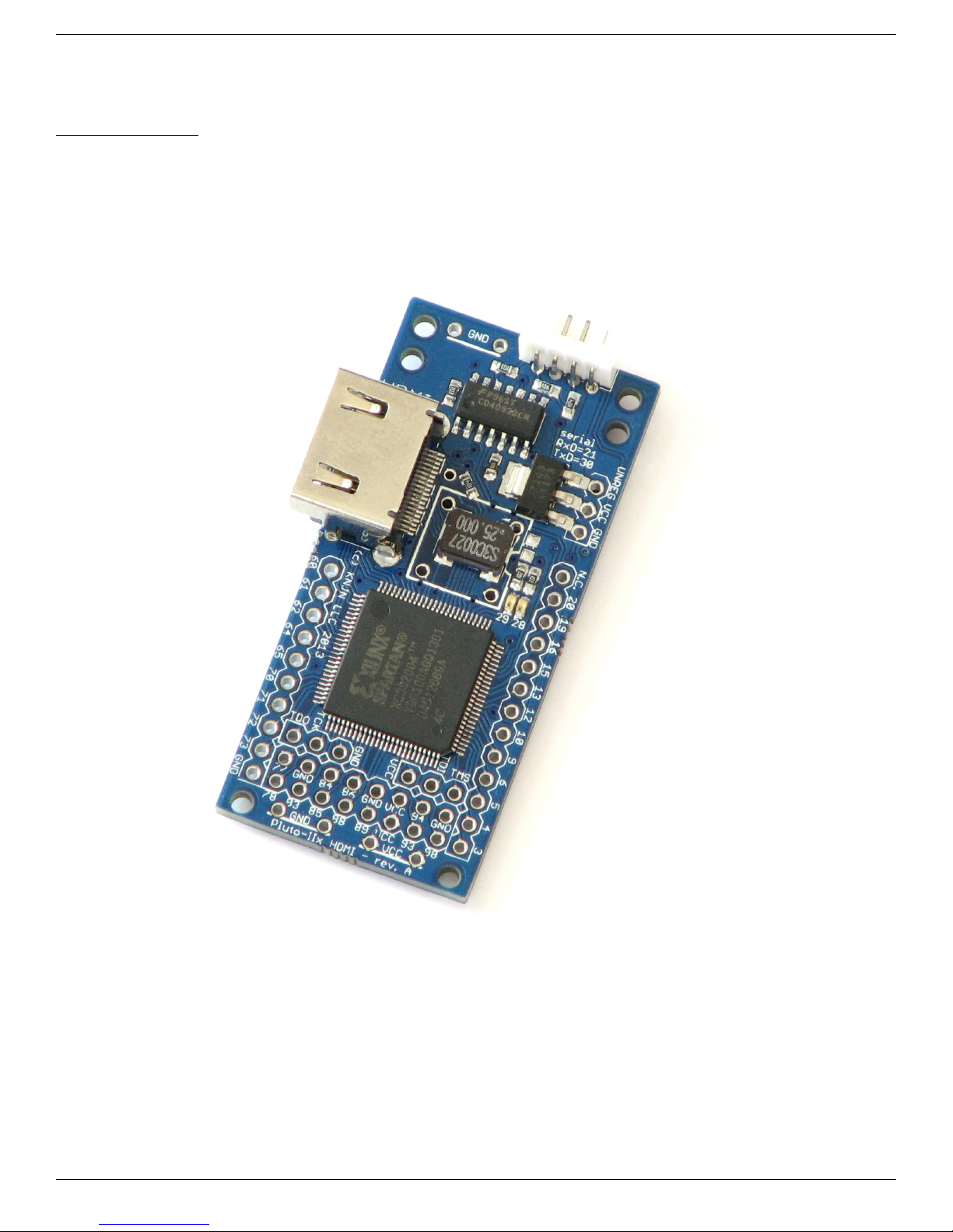
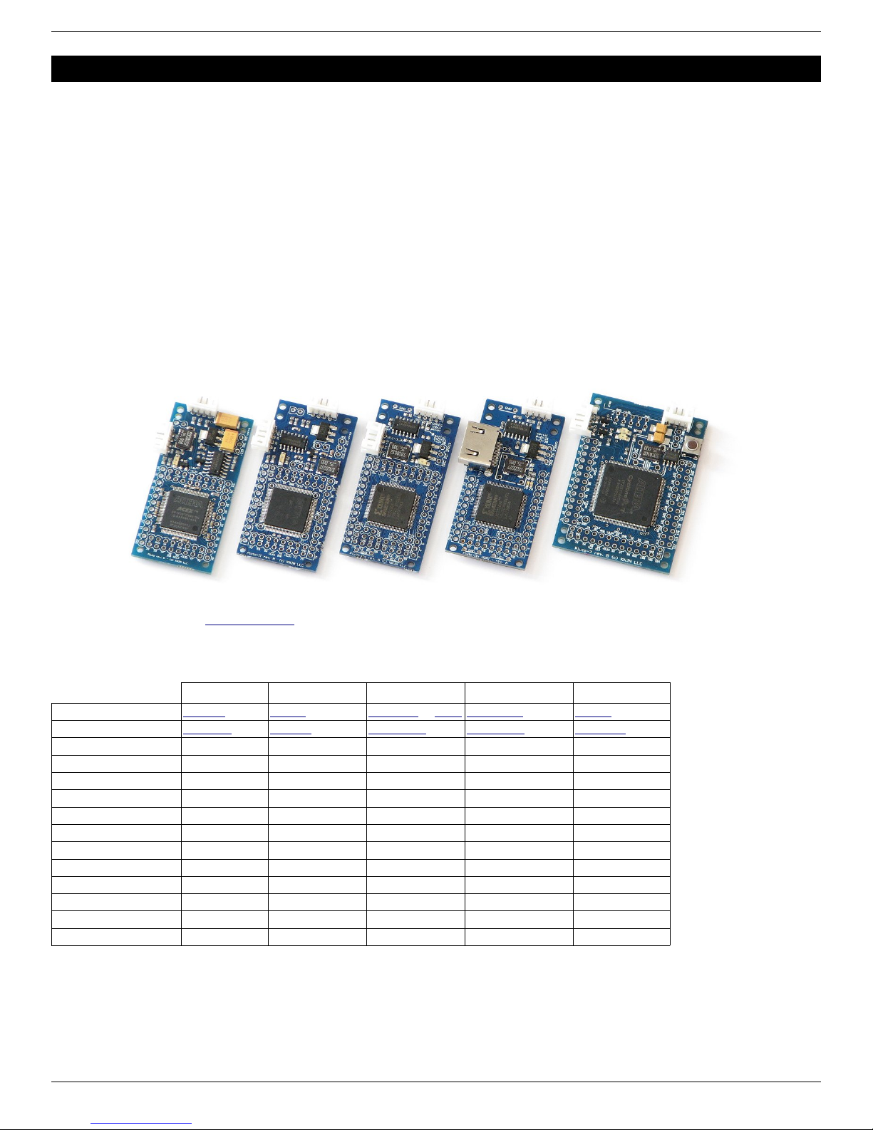
1.3 he Pluto boards........................................................................................................................................................ 5
1.4 Boards characteristics................................................................................................................................................ 5
2 Software tools..................................................................................................................................................................... 6
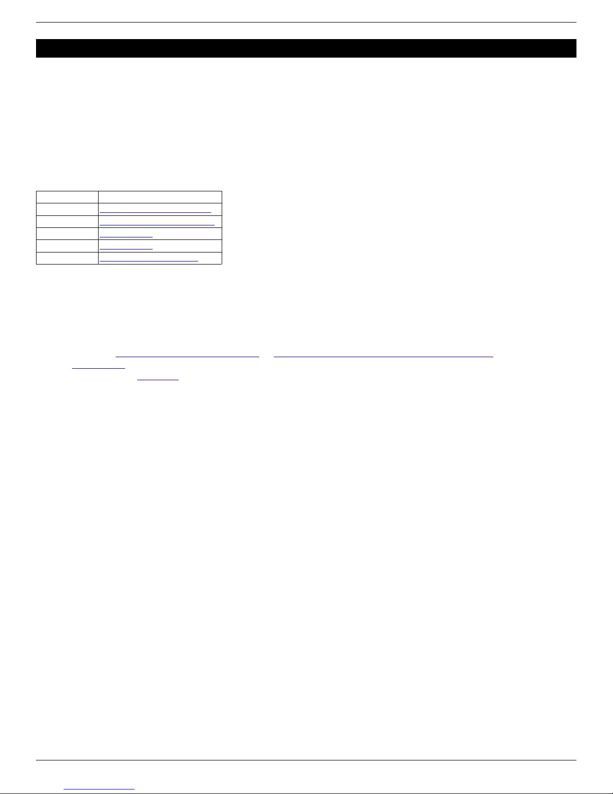
2.1 Important downloads.................................................................................................................................................. 6
2.2 FPGA software........................................................................................................................................................... 6
2.3 C/C++ compiler........................................................................................................................................................... 6
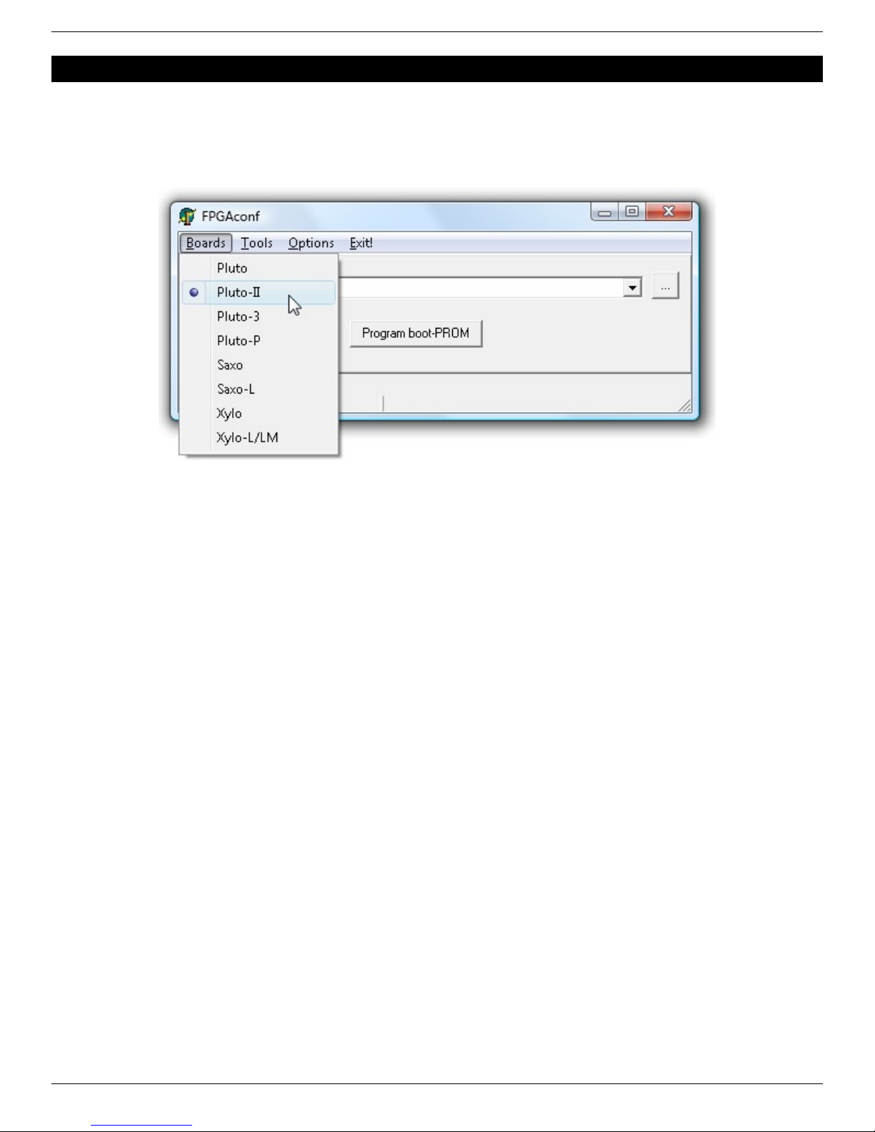
3 FPGAconf........................................................................................................................................................................... 7
3.1 Board selection........................................................................................................................................................... 7
3.2 Configuring the FPGA................................................................................................................................................ 7
3.3 FPGAconf options...................................................................................................................................................... 7
4 FPGA boot-PROM (Pluto-II/-IIx/-IIx HDMI/-3)..................................................................................................................... 8
4.1 What's the boot-PROM?............................................................................................................................................. 8
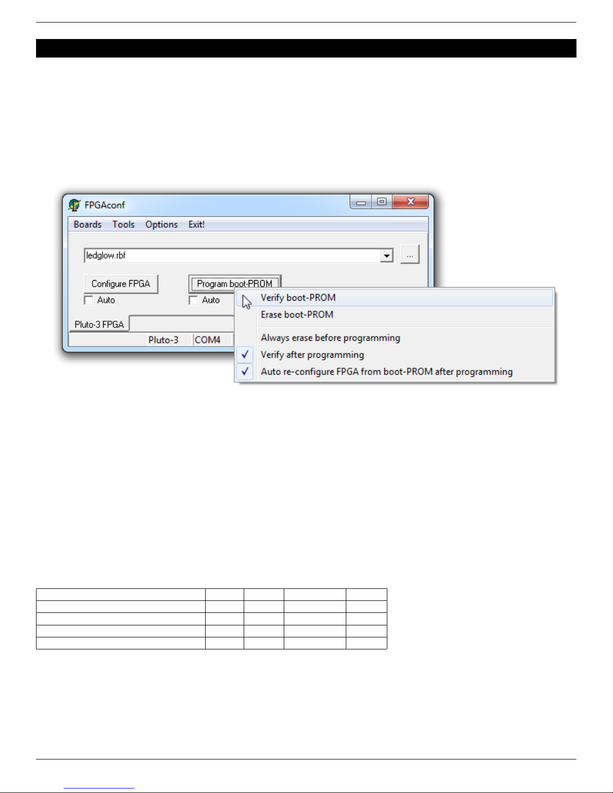
4.2 Boot-PROM actions.................................................................................................................................................... 8
4.3 Boot-PROM requirements.......................................................................................................................................... 8
4.4 Boot-PROM and J AG............................................................................................................................................... 8
4.5 Boot-PROM on-demand FPGA configuration............................................................................................................. 8
5 FPGAconf extras................................................................................................................................................................ 9
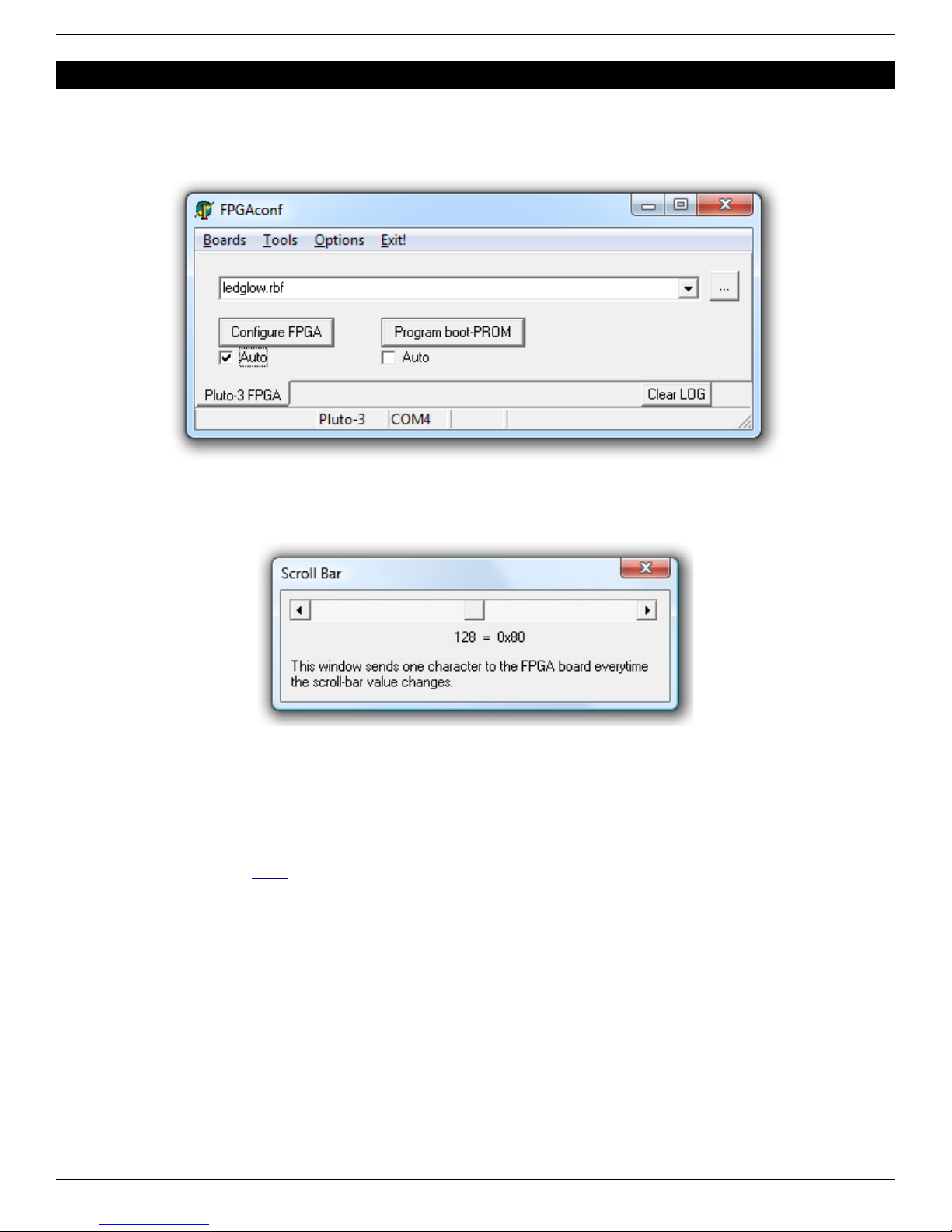
5.1 Auto configuration mode............................................................................................................................................. 9
5.2 Scrollbar..................................................................................................................................................................... 9
5.3 erminal...................................................................................................................................................................... 9
6 FPGA configuration using Quartus-II J AG support (Pluto-II/-3)......................................................................................10
6.1 J AG requirements................................................................................................................................................... 10
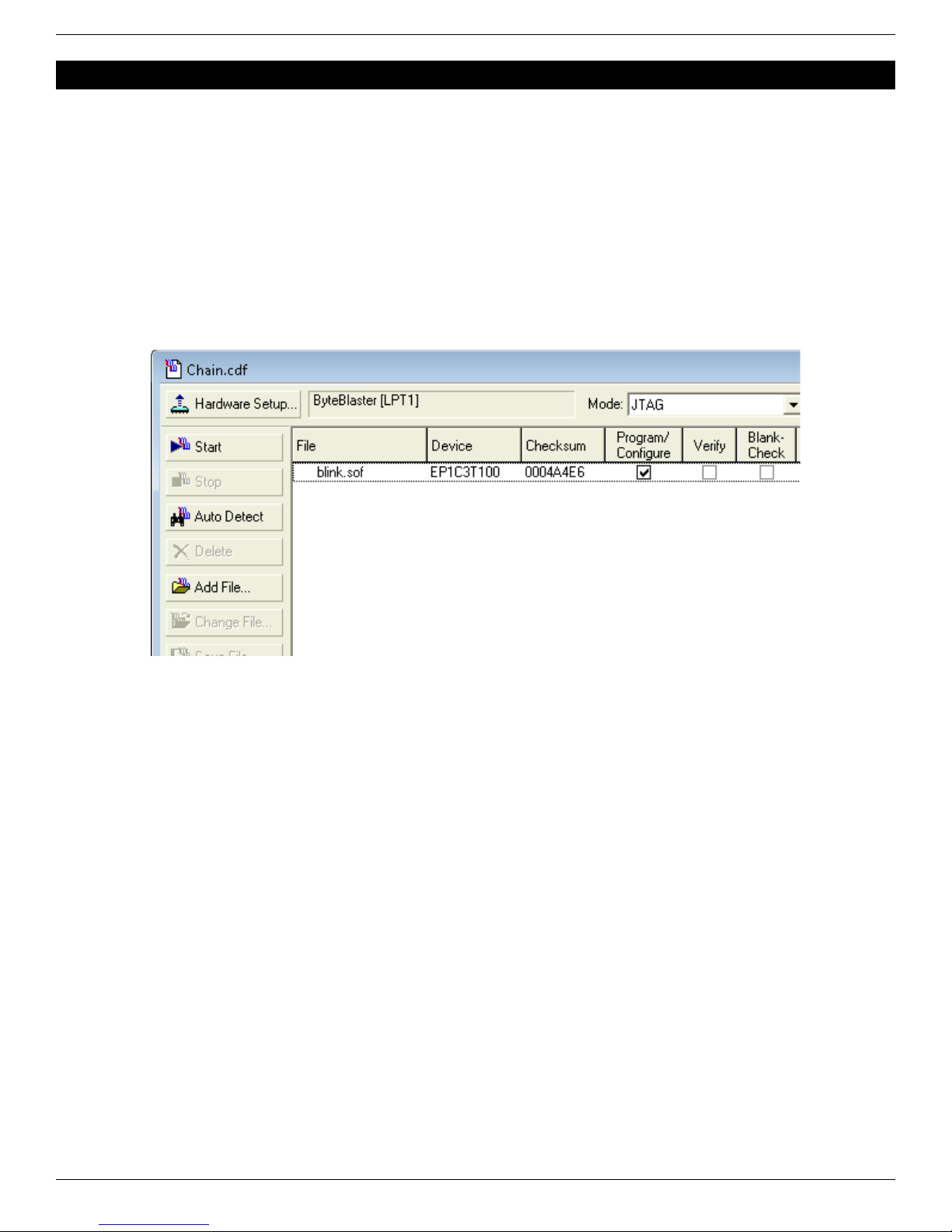
6.2 J AG configuration................................................................................................................................................... 10
7 FPGA project using Quartus-II (Pluto/-II/-3)...................................................................................................................... 11
7.1 Create a new project................................................................................................................................................. 11
7.2 A simple start............................................................................................................................................................ 11
8 FPGA projects with Xilinx's ISE (Pluto-IIx/HDMI).............................................................................................................. 12
8.1 Create a new project................................................................................................................................................ 12
8.2 A simple start............................................................................................................................................................ 12
9 FPGA connections............................................................................................................................................................ 13
9.1 FPGA pins................................................................................................................................................................ 13
9.2 IO headers................................................................................................................................................................ 13
9.3 Boot-PROM connection (Pluto-II/-IIx/HDMI/-3).........................................................................................................13
9.4 HDMI (Pluto-IIx/HDMI).............................................................................................................................................. 13
9.5 Power header........................................................................................................................................................... 13
9.6 XDI connector......................................................................................................................................................... 14
9.7 Secondary connector................................................................................................................................................ 14
10 J AG connection............................................................................................................................................................ 15
10.1 J AG on Pluto........................................................................................................................................................ 15
10.2 J AG on Pluto-II..................................................................................................................................................... 15
10.3 J AG on Pluto-IIx/HDMI......................................................................................................................................... 15
10.4 J AG on Pluto-3..................................................................................................................................................... 15
11 Flashy boards................................................................................................................................................................. 16
11.1 FlashyMini design................................................................................................................................................... 16
11.2 FlashyDemo design................................................................................................................................................ 16
12 FPGA configuration through RS-232.............................................................................................................................. 17
12.1 Pluto/-II/-IIx FPGA configuration............................................................................................................................. 17
With a UAR .............................................................................................................................................................. 17
Without a UAR ......................................................................................................................................................... 17
12.2 Pluto-3 FPGA configuration.................................................................................................................................... 17
13 Quartus-II J AG indirect mode (Pluto-II/-3).................................................................................................................... 18
13.1 What is it?............................................................................................................................................................... 18
13.2 Create a “J AG indirect configuration” file.............................................................................................................. 18
13.3 Program the boot-PROM........................................................................................................................................ 18
14 Power requirements....................................................................................................................................................... 19
14.1 Wall adapter........................................................................................................................................................... 19
14.2 USB to power jack cable......................................................................................................................................... 19
FPGA RS-232 development boards Page 2

14.3 Power consumption................................................................................................................................................ 19
14.4 Voltage regulator temperature................................................................................................................................ 19
15 Connecting the Pluto boards to a PC............................................................................................................................. 20
15.1 Serial connection.................................................................................................................................................... 20
15.2 With a XDI............................................................................................................................................................ 20
15.3 With a XDI/MAX232 or XDI/F DI....................................................................................................................... 20
15.4 Without a XDI....................................................................................................................................................... 20
16 Sample C code for RS-232 Win32 send & receive......................................................................................................... 21
17 Board checklist............................................................................................................................................................... 22
17.1 he FPGA doesn't configure?................................................................................................................................. 22
17.2 Boot-PROM problem?............................................................................................................................................ 22
18 Board connectors and headers, with IO pin assignments...............................................................................................23
18.1 Pluto....................................................................................................................................................................... 23
18.2 Pluto-II.................................................................................................................................................................... 24
18.3 Pluto-IIx.................................................................................................................................................................. 25
18.4 Pluto-IIx HDMI........................................................................................................................................................ 26
18.5 Pluto-3.................................................................................................................................................................... 27
19 Mechanical drawings...................................................................................................................................................... 28
19.1 Pluto....................................................................................................................................................................... 28
19.2 Pluto-II/-IIx/-IIX HDMI............................................................................................................................................. 29
19.3 Pluto-3.................................................................................................................................................................... 30
FPGA RS-232 development boards Page 3

FPGA RS-232 development boards Page 4

1 Welcome
1.1 This guide
Welcome to the KNJN FPGA RS-232 development boards guide.
Although FPGA boards can be intimidating, the Pluto FPGA boards are easy to use. his document is partitioned in short
and easy to read chapters, and will explain all you need to know about your new FPGA board.
1.2 Why RS-232 FPGA boards?
Although RS-232 is overshadowed by USB's popularity, RS-232 provides an easier way to interact with FPGAs, and so is
valuable as a learning tool.
1.3 The Pluto boards
his guide applies to five different boards (Pluto, Pluto-II, Pluto-IIx / HDMI and Pluto-3).
Along this document, when a paragraph apply to all of them, they are collectively named “the Pluto boards” or “the FPGA
boards”.
Check them also on the KNJN website.
1.4 Boards hara teristi s
Pluto Pluto-II Pluto-IIx Pluto-IIx HDMI Pluto-3
FPGA (vendor page) EP1K10 EP1C3 XC3S50A or 200A XC3S200A EP2C5
Datasheet (PDF) ACEX 1K Cyclone Spartan-3A Spartan-3A Cyclone II
Logic cells 576 2910 1584 or 4032 4032 4608
IO pins 41 51 48 36 65
PLL/DLL - PLL DLL DLL PLL
External clocks up to 2 up to 4 up to 4 up to 4 up to 4
Boot-PROM (1) - 1Mbit 1Mbit or 4Mbit 4Mbit 4Mbit
On-board oscillator 25MHz 25MHz 25MHz 25MHz 25MHz
DIL8 oscillator header - - - Yes Yes
Push-button - - - - Yes
JTAG header - (see chapter 10) (see chapter 10) (see chapter 10) Yes
LED(s) 1 1 1 2 2
ADC board ready Flashy / Widy Flashy / Widy Flashy / Widy Flashy / Widy FlashyD / WidyD
Dimensions 58 x 28 mm 58 x 28 mm 58 x 28 mm 58 x 28 mm 58 x 41 mm
(1) Minimum boot-PROM size shown here. Actual product may use a higher capacity boot-PROM.
FPGA RS-232 development boards Page 5

2 So tware tools
2.1 Important downloads
Each KNJN FPGA board is provided with a “startup-kit” that includes the board documentation and other files (mainly
example source code). he startup-kit doesn't include some important software tools that are required as you experiment
with your FPGA board:
●he FPGA software
●A C/C++ compiler
2.2 FPGA software
he FPGA software is required to generate FPGA bitfiles. You have to get the software that matches your FPGA.
Board So tware
Pluto Quartus II Web Edition 9.0 SP2
Pluto-II Quartus II Web Edition 11.0 SP1
Pluto-IIx ISE W eb PACK
Pluto-IIx HDMI ISE W eb PACK
Pluto-3 Quartus II Web Edition 13.0
hese software are free, don't require a license and don't expire. hey are big so you might want to download and install
them in advance.
2.3 C/C++ ompiler
A C/C++ compiler is optional but you'll need one for many projects. Here are different compilers that can be used:
●Microsoft Visual C++ 5.0 or 6.0
●Microsoft Visual C++ 2010 express edition or Visual Studio Express 2012 for Windows Desktop (free downloads)
●Digital Mars (free download)
●Jacob Navia's lcc-win32 (free download)
FPGA RS-232 development boards Page 6

3 FPGAcon
FPGAconf is a multifunction software provided with your FPGA board.
3.1 Board sele tion
FPGAconf can be used with different boards – make sure that your board is selected.
For example, we select Pluto-II below.
3.2 Configuring the FPGA
FPGAconf makes FPGA configuration very easy.
1. Select an RBF or BI bitfile (i.e. click on the browse button to select a file – the browse button is shown as “...”).
2. Click “Configure”.
After a few seconds, the FPGA should be configured. If not, see the board checklist (chapter 17).
For your convenience, sample RBF and BI files are provided in the startup-kit. In particular, try “LEDblink” and “LEDglow”
from the LED directory.
When the FPGA is not configured, the board's LED glows slightly. With practice, you’ll be able to recognize immediately if
the FPGA is configured or not.
3.3 FPGA onf options
he different settings available are:
1. “Beep after configuration”
2. “COM port” (choose from COM1 to COM32)
3. “Look for any COM port available” (if the COM port specified fails, FPGAconf uses the next port it can open)
4. “Use alternate COM port for the terminal” (useful if you want the terminal window to use a different port)
5. “Keep COM port open after configuration” (some PCs reset the Pluto board unless this is enabled)
6. “ urbo mode” (allows faster FPGA configuration, works on most boards)
FPGA RS-232 development boards Page 7

4 FPGA boot-PROM (Pluto-II/-IIx/-IIx HDMI/-3)
4.1 What's the boot-PROM?
he boot-PROM is a serial flash memory that is read by the FPGA at power-up to get configuration data. If the boot-
PROM is empty or its content is invalid, the FPGA stays un-configured and the boot-PROM gets “out of the way” to allow
FPGA configuration from another source (RS-232 or J AG).
4.2 Boot-PROM a tions
he boot-PROM can be programmed, verified and erased.
●o program the boot-PROM, select a bitfile and left-click on the “Program boot-PROM” button.
●o verify or erase the boot-PROM, right-click on the button and use the drop-down menu.
4.3 Boot-PROM requirements
FPGAconf requires bi-directional communication with the PC to access the boot-PROM. If the boot-PROM is not
recognized by FPGAconf, try the SerialRx x project to diagnose the communication.
4.4 Boot-PROM and JTAG
he boot-PROM can also be programmed from J AG, although it is usually less convenient.
●For Pluto-II and Pluto-3, use Quartus-II J AG indirect mode (chapter 13).
●For Pluto-IIx, use ISE iMPAC (part of ISE WebPACK).
4.5 Boot-PROM on-demand FPGA onfiguration
On the Pluto-IIx/HDMI/-3 boards, the boot-PROM can also configure the FPGA “on-demand” (i.e. under software control
after power-up).
Here's a summary of all the boot-PROM features.
Boot-PROM Pluto-II Pluto-IIx Pluto-IIx HDMI Pluto-3
Configures FPGA at power-up Yes Yes Yes Yes
Can be programmed through RS-232 Yes Yes Yes Yes
Can be programmed through J AG Yes Yes Yes Yes
Configures FPGA on-demand (after power-up) No Yes Yes Yes
FPGA RS-232 development boards Page 8

5 FPGAcon extras
5.1 Auto onfiguration mode
When the “Auto mode” is enabled, FPGAconf monitors the bitfile and takes action each time the file is updated. Useful for
example if you want to re-configure the FPGA automatically after each ISE or Quartus-II compilation,.
5.2 S rollbar
FPGAconf has a “scrollbar window” that is activated by pressing C RL-S. Every time the scrollbar position is changed, a
byte between 0 and 255 is sent to the Pluto board (depending of the bar position).
hat can be used to control easily a servomotor for example, or other simple applications that can be controlled by a
single byte.
5.3 Terminal
FPGAconf has an RS-232 terminal window that is activated by pressing C RL- .
Note: you can also use a third-party terminal, but it is recommended in this case to use a XDI with MAX232. See
paragraph 15.3 and KNJN's XDI page for more information.
FPGA RS-232 development boards Page 9

6 FPGA con iguration using Quartus-II JTAG support (Pluto-II/-3)
6.1 JTAG requirements
o use the J AG port, you need a compatible J AG cable (like an Altera ByteBlaster-MV/II or USB-Blaster) connected to
your board's J AG connector (chapter 10).
6.2 JTAG onfiguration
Follow these steps:
●In Quartus-II, open the “Programmer” window (Menu → ools → Programmer)
●Click on the “Hardware Setup” button and select the J AG cable you’re using.
●Select “J AG” in the “Mode” drop-down list.
●Load the “.sof” file.
●Check the “Program/Configure” check-box and click “Start”.
Note how J AG configuration is accomplished through the Quartus-II software using SOF files instead of RBF files. Both
files are generated by Quartus-II – more details in paragraph 7.2.
he boot-PROM can also be programmed using J AG, check chapter 13 for more information.
FPGA RS-232 development boards Page 10

7 FPGA project using Quartus-II (Pluto/-II/-3)
Pluto, Pluto-II and Pluto-3 are configured from SOF or RBF files generated by Altera’s Quartus-II software.
7.1 Create a new proje t
1. Run Quartus-II, and click on menu → File → New Project
Wizard.
2. Select the project location, choose a project name, and click
Next.
3. Choose files to add to the project. Just click next if you don't
have files to add now.
4. Now is time to choose the device (you can also do that later
using menu → Assignments → Device)
a. For Pluto, choose family “APEX1K” and device
“EP1K10 C100-3”.
b. For Pluto-II, choose family “Cyclone” and device
“EP1C3 100C8”.
c. For Pluto-3, choose family “Cyclone-II” and device
“EP2C5 144C8”.
5. Click Finish.
A graphical work-through is also available on this fpga4fun page.
7.2 A simple start
Here’s a simple Verilog file:
module LEDblink(input clk, output LED);
// 32 bits counter
reg [31:0 cnt;
always @(posedge clk) cnt <= cnt + 1;
assign LED = cnt[23 ;
endmodule
Add it to the project and select it as the top-level design. Next make the correct pin assignments in Quartus-II menu →
Assignments/Pins or “Pin planner” (using the info from paragraph 9.1). his project uses only 2 pins, so it should be fast.
You also want to specify the outputs and what happens to unused pins.
1. Select menu → Assignments → Device
2. Click on “Device & Pin Options…”
a. Go to the “Programming Files” tab, select “Raw Binary File (.rbf)”.
b. Go to Unused Pins”, select “As inputs, tri-stated” or “As inputs with weak pull-up”.
c. Click “OK”.
3. Click “OK”.
Option 2.a makes sure RBF files are generated (used for RS-232 FPGA configuration). Otherwise only SOF files are
generated (used for J AG).
Option 2.b is optional but highly recommended. It prevents the FPGA from driving pins that are not used in your project.
Otherwise, Quartus-II drives all the unused pins to ground, which often ends-up creating IO contentions.
FPGA RS-232 development boards Page 11

8 FPGA projects with Xilinx's ISE (Pluto-IIx/HDMI)
he Pluto-IIx board is configured from BI files generated by Xilinx's ISE software.
8.1 Create a new proje t
1. Run ISE Project Navigator, and click on menu → File →
New Project.
2. Choose a project name, select the project location, and
click Next.
3. Select the “Spartan3A and Spartan3AN” family and the
device on your board, either
●XC3S50A in VQ100 package
●XC3S200A in VQ100 package
4. Click Next twice and Finish to close the wizard.
You can now create or add source files in the project.
A graphical work-through is also available on this fpga4fun page.
8.2 A simple start
Here’s a simple Verilog file:
module LEDblink(input clk, output LED);
// 32 bits counter
reg [31:0 cnt;
always @(posedge clk) cnt <= cnt + 1;
assign LED = cnt[23 ;
endmodule
Add it to the project and select it as the top-level design in your project.
Now add this UCF file to the project.
NET "clk" LOC = P40;
NET "LED" LOC = P29;
Finally right-click on “Generate Programming File” and
choose “Process Properties”. In “Configuration Options”,
allow “Unused IOB Pins” to “Float”. hat prevents the FPGA
from driving the pins that are not used in your project.
Otherwise grounding all the unused pins (the default) often
ends-up creating IO contentions.
FPGA RS-232 development boards Page 12

9 FPGA connections
9.1 FPGA pins
he main FPGA signals are:
Pin name Pluto Pluto-II Pluto-IIx Pluto-IIx HDMI Pluto-3 Direction Comment
CLK0 91 10 40 40 17 FPGA input 25MHz on-board SMD oscillator, always present
CLK1 41 18 FPGA input Optional DIL8 oscillator (1)
LED1 7 25 29 29 28 FPGA output Red LED (active high)
LED2 28 25 FPGA output Red LED (active high)
PB 9 FPGA input Push-button (active low)
RxD 77 4 21 21 21 FPGA input FPGA receives from PC
TxD 78 29 30 30 24 FPGA output FPGA transmits to PC
(1) he optional oscillator is not present by default. It is to be added above the on-board SMD oscillator.
9.2 IO headers
Many IO signals are available on headers, see the drawings on chapter 18.
9.3 Boot-PROM onne tion (Pluto-II/-IIx/HDMI/-3)
he boot-PROM is an M25P10 or M25P40 or equivalent.
he pinout is as follow:
Boot-PROM
pin
Pluto-II
FPGA pin
Pluto-IIx / HDMI
FPGA pin
Pluto-3
FPGA pin
Clock 20 53 15
Data In 17 46 1
Data Out 5 51 14
CSn 6 27 2
HOLDn 40 31 8
Wn 89 N.A. N.A.
9.4 HDMI (Pluto-IIx/HDMI)
Each HDMI port uses 8 FPGA pins (4 differential pairs), plus some auxiliary lines (DDC I2C and “hot plug detect”).
●Pluto-IIx board: it doesn't have a native HDMI port but can be fitted with an optional HDMI adapter.
●Pluto-IIx HDMI board: it has a native HDMI port, and can also use an optional HDMI adapter, so in effect has two
possible HDMI outputs.
TMDS clock TMDS 0 (blue) TMDS 1 (green) TMDS 2 (red) I2C SDA I2C SCL Hot plug detect
Pluto-IIx HDMI (native output) 34 / 35 36 / 37 (1) 43 / 44 (1) 48 / 49 50 33 32
Pluto-IIx optional HDMI adapter 77 / 78 83 / 84 (1) 88 / 89 (1) 93 / 94 (2) (2) (2)
(1) Inverted MDS lane – place an inverter in the FPGA. See the HDMI source code “ MDS_encoder” instantiations.
(2) If desired, the HDMI auxiliary lines can be wired manually to the FPGA.
9.5 Power header
his 3-pins header provides access to the power signals. It is often used as an output (to power other boards) but can
also be used as an input (to power the Pluto board).
On Pluto and Pluto-II, the power header pinout is:
1. VCC-unreg (board power, typically +5V to +10V)
2. GND
3. +3.3V (regulated by Pluto/Pluto-II)
On Pluto-IIx/HDMI and Pluto-3, the power header pinout is:
1. GND
2. +3.3V (regulated by Pluto-IIx/HDMI/-3)
3. VCC-unreg (board power, typically +5V to +10V)
FPGA RS-232 development boards Page 13

9.6 TXDI onne tor
It is usually used to power the Pluto board and for RS-232 communication.
1. GND
2. xD (FPGA → PC)
3. RxD (PC → FPGA)
4. VCC-unreg (board power, typically +5V to +10V)
See chapter 15 for more information.
9.7 Se ondary onne tor
he secondary connector is placed on the left side of the board. If it is not present, it can be easily soldered (available as
KNJN item#180 4 or from DigiKey).
he secondary connector has only 4 pins (2 power pins and 2 IOs), and so is usually limited to applications requiring a
serial bus. Possible applications include:
●Graphic LCD
●I²C interface
he pin assignments are:
Pin Pluto Pluto-II Pluto-IIx Pluto-IIx HDMI Pluto-3 Comment
1VCC-unreg VCC-unreg 3.3V 3.3V VCC-unreg Power
2FPGA IO pin 8 FPGA IO pin 26 FPGA IO pin 43 FPGA IO pin 57 FPGA IO pin 30 RxD or serclk or other use
3FPGA IO pin 96 FPGA IO pin 27 FPGA IO pin 44 FPGA IO pin 59 FPGA IO pin 31 xD or serdata or other use
4GND GND GND GND GND Ground
In more details:
●VCC-unreg is the voltage that you power your FPGA board with, typically +5V to +10V.
On Pluto and Pluto-II, VCC-unreg can be disconnected from the secondary connector by cutting the trace placed
between the two pads close to the VCC-unreg pin.
●Pins 2 & 3 are two FPGA IO pins. he board includes series termination resistors, and Zener protection diodes on
these 2 signals (Pluto/-II/-3 only).
●Some revisions of Pluto-II have another secondary connector on the right side of the board, below the power
header.
FPGA RS-232 development boards Page 14

10 JTAG connection
10.1 JTAG on Pluto
J AG is not available on Pluto.
10.2 JTAG on Pluto-II
he Pluto-II's FPGA J AG signals are only accessible at the bottom of the board.
o use J AG, get a J AG cable (like a ByteBlaster or USB-Blaster), and solder the J AG signals to the pads shown
above.
10.3 JTAG on Pluto-IIx/HDMI
he Pluto-IIx J AG signals are accessible on pin headers next to the FPGA.
10.4 JTAG on Pluto-3
Pluto-3 has the regular Altera-style 10 pins header. A matching shrouded connector must be added to the board, like
KNJN items 2450 or 2451, so that an Altera or compatible J AG cable can easily be used.
FPGA RS-232 development boards Page 15

11 Flashy boards
When a Flashy board is used in combination with a KNJN FPGA board, the system becomes a digital oscilloscope.
11.1 FlashyMini design
FlashyMini is provided with full source code (HDL + C). It shows how to get data from Flashy and can be used as a
skeleton to develop your own acquisition system.
11.2 FlashyDemo design
FlashyDemo is provided in binary form. It is a showcase of Flashy possibilities, implementing features found in digital
oscilloscopes like pre-trigger acquisition and equivalent-time-sampling.
o run FlashyDemo:
1. Mount Flashy on the Pluto board, and power it up (see also the Hands-on - A digital oscilloscope page).
2. Configure the FPGA with the FlashyDemo bitfile.
3. Go to Menu → ools → Flashy Oscilloscope (or press C RL-F).
Note that there are actually three kind of Flashy boards available (Flash, Flashy and FlashyD).
Here's the compatibility table.
Flash Flashy FlashyD LCD (2)
Pluto Limited (1) Limited (1) No No
Pluto-II Yes Yes No Yes
Pluto-IIx / HDMI Yes Yes No Yes
Pluto-3 Yes Yes Yes Yes
(1) Pluto's FPGA cannot hold all the FlashyDemo functionality at once, so two FlashyDemo bitfiles are provided. Each covers a different
set of features.
(2) he KNJN color LCD item#5300 option can work as a FlashyDemo external display.
For more information, check KNJN's Flashy acquisition board page.
FPGA RS-232 development boards Page 16

12 FPGA con iguration through RS-232
12.1 Pluto/-II/-IIx FPGA onfiguration
Unlike Pluto-II/-IIx and Pluto-3, Pluto doesn’t have an FPGA boot-PROM, so Pluto needs to be configured after each
power-up. his is usually done through the serial port of a PC, but it can also be accomplished using a microcontroller
(using only one output pin).
here are 2 techniques, depending on the presence or absence of a UAR in your microcontroller.
With a UART
Set the microcontroller UAR at 115200 bauds, and run the following C pseudo-code:
For each byte of the RBF file, do:
for(j=0; j<8; j++) serial.write(((rbfbyte >> j) & 1) ? 0xFF : 0xFE);
A more complete example could be:
int i, j;
FILE *fpIn = fopen("LEDblink.rbf", "rb" );
char buf[0x10000 ;
int len = fread(buf, 1, sizeof(buf), fpIn);
fclose(fpIn);
OpenCom();
SetCommBreak(hCom); Sleep(50); // un-configure FPGA
ClearCommBreak(hCom);
for(i=0; i<len; i++)
for(j=0; j<8; j++)
WriteComChar(((buf[i >> j) & 1) ? 0xFF : 0xFE); // 8.6µs or 17.3µs pulses
CloseCom();
his code also work from a PC, see the chapter 16 for some COM source code.
Without a UART
If your microcontroller doesn’t have a UAR , you can just send pulses on one IO pin. Sending 0xFF above is equivalent to
sending a pulse of 8.6µs, while sending 0xFE sends a pulse twice that long. Pulses are positive (inactive level is “0”) and
they need to be separated by 30µs or so between them. o un-configure Pluto (before sending the RBF), send a “break”
condition (a high signal) for about 50ms.
he RBF file is a binary file which is usually compressible, in case you run out of memory in the microcontroller.
12.2 Pluto-3 FPGA onfiguration
Pluto-3's configuration scheme is even simpler. o configure the FPGA, just send the RBF binary content through RS-232
at 115200 bauds in 8-bits mode. o un-configure the FPGA (before sending the RBF), send a “break” condition (a high
signal) for about 50ms.
On Linux, this script could be used.
#!/bin/bash
#
# pluto3configure :: send an rbf file to a Pluto-3 FPGA board
#
SERIAL=/dev/ttyUSB0
if [ ! -f "$1"
then
echo "Usage: $(basename $0) filename.rbf" >&2
exit 1
fi
(stty 115200 raw cs8 -cstopb -parenb -ixon -crtscts 0<&1 ; sendbreak; dd "if=$1" bs=1k) > $SERIAL
FPGA RS-232 development boards Page 17

13 Quartus-II JTAG indirect mode (Pluto-II/-3)
13.1 What is it?
he J AG indirect mode allows programming the FPGA boot-PROM through J AG.
It is a two steps process: first a .jic (“J AG indirect configuration”) file is created, and then the .jic file is used to program
the boot-PROM
13.2 Create a “JTAG indire t onfiguration” file
1. In Quartus-II, go to File → Convert programming file
2. In the “Output programming file” panel, select “J AG Indirect Configuration File”, EPCS1 for Pluto-II or EPCS4
for Pluto-3, and a filename for a “.jic” file.
3. In “Input file to convert”, select the Cyclone EP1C3 for Pluto-II or EP2C5 for Pluto-3 as “Flash loader”, and the
SOF file that you want to use for the boot-PROM as “SOF Data”.
4. Click “OK”. his creates the “.jic” file.
he boot-PROM can now be programmed.
13.3 Program the boot-PROM
1. Open the “Programmer” window (in ools → Programmer)
2. Select the J AG cable you are using (“Hardware Setup” button)
3. Select J AG as “Mode”
4. Load the “.jic” file
5. Select configure for both the FPGA (EP1C3/EP2C5) and the boot-PROM (EPCS1/EPCS4)
6. Click the “Start” button.
7. You can also verify and erase the boot-PROM if you want (note: the FPGA doesn’t need to be re-configured if
it is already configured from the jic).
For more information, check Altera's AN-370.
FPGA RS-232 development boards Page 18

14 Power requirements
he Pluto boards have their own voltage regulator, so don't have stringent requirements on a power supply.
14.1 Wall adapter
Most common (semi-regulated) 5V to 10V “wall adapter” DC
supply works fine.
In practice, the Pluto boards work with an input voltage as low
as 4.5V, or as high as 15V (although the voltage regulator
might become hot in the later case, so it is better to keep the
input voltage low).
14.2 USB to power ja k able
he “USB to power jack cable” (picture on the right) is another simple way to power
the Pluto boards. It is available on KNJN's power cables page (item#6025).
14.3 Power onsumption
he Pluto boards don’t consume much by themselves (usually less than 100mA). he
consumption depends more of what you connect to them. A supply that provides a
few 100mA is adequate for most applications.
14.4 Voltage regulator temperature
he Pluto boards voltage regulator can get hot in some instances.
Here are the two things to do in this case:
1. Check your DC-adapter output voltage. he higher it is, the warmer the voltage regulator gets, so try to use one
adapter with a low voltage output (+5V is ideal).
2. Check the current consumption: the more current drawn out of the regulator, the warmer it gets. So if your FPGA
board is heavily loaded (lots of IOs connected), the regulator may get hot.
If the voltage regulator gets too hot, it shuts down automatically and the board stops working temporarily.
FPGA RS-232 development boards Page 19

15 Connecting the Pluto boards to a PC
15.1 Serial onne tion
he Pluto boards connects to a PC's RS-232 port.
he recommended way is through a XDI board, although it is not mandatory. he XDI board simplifies the Pluto boards
connection as it combines the bulky RS-232 connection and the power connection into one cable. If a XDI is not desired,
a simple DB-9 connector can be used.
15.2 With a TXDI
Connect the Pluto and XDI has shown below (the small multi-color cable between the two is provided).
IMPORTANT: Make sure the DC-plug is center-positive.
15.3 With a TXDI/MAX232 or TXDI/FTDI
he XDI/MAX232 and XDI/F DI are more versatile than the regular XDI as they can also be used with the secondary
connector (to create a second RS-232 port).
XDI connector:
●With XDI/MAX232, place the jumper on the “B” position.
●With XDI/F DI, xD needs to be inverted (use F DI's F _PROG utility if required).
Note: the XDI/F DI board resets the FPGA when the USB cable is plugged, which may prevent or disturb the
FPGA boot-PROM configuration process at start-up.
Secondary connector:
●With XDI/MAX232, place the jumper on the “M” position.
●With XDI/F DI, don't invert the xD line (use F DI's F _PROG utility if required).
15.4 Without a TXDI
In the absence of a XDI, the Pluto boards are shipped with a small cable. Connect it to a DB-9 female connector as
follow:
●White wire to DB-9 pin 3.
●Black wire to DB-9 pin 5 and power supply GND.
●Red wire to DC power supply (+5V to +10V).
In short, the board is powered using the black and red wires, and the PC sends data to the board through the white wire.
Note that this method provides only unidirectional communication with the FPGA board (the PC can send RS-232 data to
the FPGA, but the FPGA cannot send data to the PC) so cannot be used to program the Pluto-II/-IIx/-3 boot-PROM.
FPGA RS-232 development boards Page 20
This manual suits for next models
4
Table of contents