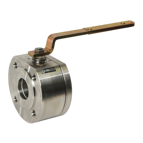
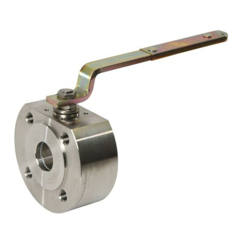
Adler FA1 User manual

Adler SpA Valvole a sfera –- V.le Borletti , 14 - 20010 S. Stefano Ticino (MI) - ITALY
Tel. +39 - 0297484211 – Fax. +39 - 0297271698 - Web Site: www.adlerspa.com - E-mail: adler@adlerspa.com
Pag.
1
di
7
Mod. 20 Rev. 4
U
US
SE
ER
R
M
MA
AN
NU
UA
AL
L
:
:
C
CO
ON
NS
SI
ID
DE
ER
RA
AT
TI
IO
ON
NS
S
O
OF
F
T
TE
EC
CH
HN
NI
IC
CA
AL
L
R
RI
IS
SK
K
U
US
SE
E
/
/
I
IN
NS
ST
TA
AL
LL
LA
AT
TI
IO
ON
N
/
/
M
MA
AN
NT
TE
EI
IN
NA
AN
NC
CE
E
CONSIDERATIONS OF TECHNICAL RISK
Adler S.p.A. ball valves, if provided of CE marking are manufactured in accordance with P.E.D. directive (97/23/EC) and/or ATEX directive (94/9/EC)
and/or machinery directive (98/37/EC), but they don’t consider in their design the following factors of risk:
1) Adler S.p.A.“Standard” ball valves can be used in a temperature range between –28.8 / + 250 °C. For service temperatures below – 28.8 °C ball
valves construction materials shall be submitted to an impact test at the minimum service temperature. For temperatures between – 28.8 °C &
+ 250 °C ball valves have to be provided with seats & seals able to withstand the temperature degree required (Adler S.p.A. technical support is
suggested to select the suitable seats & seal material).
2) Adler S.p.A.“Standard” ball valves are not equipped with devices suitable to avoid internal over-pressures caused by incorrect operations of
process or by fluids & liquids subjected to an increase of volume and/or pressure. (These devices, such as the over-pressure hole into the ball or
the safety relief seats are available upon request).
3) Adler S.p.A.“Standard” ball valves are not designed with special devices to withstand a sudden thermal jump (thermal Shock).
4) Adler S.p.A.“Standard” ball valves are not equipped with “Fire Safe” seals. (“Fire Safe” ball valves certified BS 6755 are supplied upon request).
5) In general Adler S.p.A.“Standard” ball valves are not mechanically designed to bear over loads due to exceptional atmospheric or natural
phenomenon’s (Ex. earthquakes).
6) In general Adler S.p.A.“Standard” ball valves are not designed to bear loads on flanges, on pipe connections or pipe-line.
7) In general Adler S.p.A.“Standard” ball valves can’t withstand with ice inside their bodies. (In this case user has to consider the optional stem
extension for insulating, avoiding the presence of residual product inside the valve).
8) Adler S.p.A. ball valves are suitable for low temperature service (up to – 196°C) when provided of cryogenic stem extension (available on
request).
9) Adler S.p.A. ball valves are suitable “industrial” oxygen service when supplied degreased and packed in polyethylene bags only.
N.B. For “medical” oxygen service please contact Adler S.p.A.
10) The compatibility between ball valves construction materials and mediums is selected by the user. Adler S.p.A.personnel are at your disposal for
additional technical aid, but the user is ultimately responsible for verifying the compatibility between medium and materials.
MARKING
E
Ea
ac
ch
h
b
ba
al
ll
l
v
va
al
lv
ve
e
i
is
s
i
id
de
en
nt
ti
if
fi
ie
ed
d
w
wi
it
th
h
t
th
he
e
f
fo
ol
ll
lo
ow
wi
in
ng
g
d
da
at
ta
a:
:
d
da
at
te
e
o
of
f
p
pr
ro
od
du
uc
ct
ti
io
on
n,
,
t
ty
yp
pe
e,
,
n
no
om
mi
in
na
al
l
d
di
ia
am
me
et
te
er
r,
,
r
ra
at
ti
in
ng
g,
,
m
ma
at
te
er
ri
ia
al
ls
s
a
an
nd
d
h
he
ea
at
t
n
nu
um
mb
be
er
r.
.
F
Fu
ur
rt
th
he
er
r
P
P.
.E
E.
.D
D.
.
b
ba
al
ll
l
v
va
al
lv
ve
e
i
is
s
m
ma
ar
rk
ke
ed
d
w
wi
it
th
h
C
CE
E
l
lo
og
go
o
f
fo
ol
ll
lo
ow
we
ed
d
b
by
y
t
th
he
e
n
no
ot
ti
if
fi
ie
ed
d
b
bo
od
dy
y
i
id
de
en
nt
ti
if
fi
ic
ca
at
ti
io
on
n
n
nu
um
mb
be
er
r
a
an
nd
d
b
by
y
t
th
he
e
s
se
er
ri
ia
al
l
n
nu
um
mb
be
er
r.
.
I
If
f
t
th
he
e
b
ba
al
ll
l
v
va
al
lv
ve
es
s
h
ha
as
s
t
to
o
b
be
e
a
al
ls
so
o
A
AT
TE
EX
X
c
ce
er
rt
ti
if
fi
ie
ed
d,
,
t
th
he
e
C
CE
E
m
ma
ar
rk
ki
in
ng
g
w
wi
il
ll
l
b
be
e
f
fo
ol
ll
lo
ow
we
ed
d
b
by
y
e
ex
xp
pl
lo
os
si
io
on
n-
-p
pr
ro
oo
of
f
l
lo
og
go
o
Ɛ
Ɛ
x
x,
,
t
th
he
e
n
nu
um
mb
be
er
r
o
of
f
t
th
he
e
g
gr
ro
ou
up
p,
,
t
th
he
e
c
ca
at
te
eg
go
or
ry
y,
,
t
th
he
e
l
le
et
tt
te
er
r
“
“G
G”
”
(
(r
re
el
la
at
ti
iv
ve
e
t
to
o
t
th
he
e
e
ex
xp
pl
lo
os
si
iv
ve
e
a
at
tm
mo
os
sp
ph
he
er
re
e
d
du
ue
e
t
to
o
t
th
he
e
p
pr
re
es
se
en
nc
ce
e
o
of
f
g
ga
as
s,
,
v
va
ap
po
ou
ur
rs
s
o
or
r
f
fo
og
gs
s)
)
a
an
nd
d/
/o
or
r
b
by
y
t
th
he
e
l
le
et
tt
te
er
r
“
“D
D”
”
(
(r
re
el
la
at
ti
iv
ve
e
t
to
o
t
th
he
e
e
ex
xp
pl
lo
os
si
iv
ve
e
a
at
tm
mo
os
sp
ph
he
er
re
e
d
du
ue
e
t
to
o
t
th
he
e
p
pr
re
es
se
en
nc
ce
e
o
of
f
d
du
us
st
ts
s)
).
.
BALL VALVE START-UP
Before installing the ball valve on the pipe-line it is mandatory, for the user, to verify the compatibility of the ball valve with service conditions (medium,
temperature and pressure). With reference to standard ball valves stocked on shelves by wholesalers they will have to assure themselves about the
compatibility with the use conditions required by the customer. Alternatively with reference to the “consideration of technical risk”, they’ll have to ask to
Adler S.p.A. to suggest the suitable product for the specific utilization required.
Adler S.p.A. Ball Valves must be only used for on-off (fully open/ fully close) service.
It’s mandatory to consult Adler S.p.A. Technical Department before using ball valves for regulating service.
Before using the ball valve in a potential explosive atmosphere it’s necessary:
•to verify the compatibility between the ball valve and the zone in which the ball valves should be installed (see directive 99/92/CE);
•to foresee the pipe-line ground connection on which the ball valve should be installed;
•to check that the temperature of the ball valve surface is not higher than the flammable point of the atmosphere in which the ball valve is installed
(in this case foresee an insulating cover device for the valve and an extension for the wrench) ;
•before installing ball valves with welding ends to make sure that the process of welding is realized respecting all the safety norms the classified
zone requires;
•to avoid mechanical knocks during the installation that may cause sparks.
REMARK : Adler S.p.A. cannot be held responsible for damage caused by improper use or modification of the product.
8805.82/EN

Adler SpA Valvole a sfera –- V.le Borletti , 14 - 20010 S. Stefano Ticino (MI) - ITALY
Tel. +39 - 0297484211 – Fax. +39 - 0297271698 - Web Site: www.adlerspa.com - E-mail: [email protected]
Pag.
2
di
7
Mod. 20 Rev. 4
BALL VALVE INSTALLATION
Before installation it is necessary:
•To verify that the rating marked on the body valve is higher than the working pressure;
•To be sure that the pipe-line is free from residual of weldings, rubbish, shavings and every kind of extraneous materials;
•To check for the absence of extraneous particles (ground, dust, etc.) in the passage, on seat and ball surface if ball valve has been stocked without
plastic caps of protection.
•To remove plastic caps of protection;
•To operate the ball valve twice (open and close);
•To verify if the weight or the dimension of the ball valve require more workers for transport and installation.
•Flanged ball valves need gaskets interposed between them and counter-flanges. (These gaskets are not supplied by Adler S.p.A.)
To assemble flanged ball valves to the pipe-line it’s necessary to use screws or stud bolts fixed by a torque meter key. The torque values are available on
“Table 1” and “Table 2”.
For split valves (three parts) with welding ends, set the valve on piping, make three welding point to fix the ends of the valve, unscrew and remove
tie-rods and then slip off the central body of the valve. Finally complete the welding and reassemble the body valve.
Metric Threads
Drilling Dimensions
Carbon Steel screws torque
(Nm)
Stainless Steel screw torque
(Nm)
M 5 6 3 . 8
M 6 1 0 . 4 6 . 5
M 8 2 4 . 6 1 5 . 4
M 1 0 5 0 . 1 3 1 . 3
M 1 2 8 4 . 8 5 3
M 1 4 1 3 5 8 4 . 3
M 1 6 2 0 5 1 2 8
M 1 8 2 8 3 1 7 7
M 2 0 4 0 0 2 5 0
M 2 2 5 3 2 3 2 2
M 2 4 6 9 1 4 3 2
M 2 7 1 0 1 0 6 3 1
M 3 0 1 3 7 0 8 5 7
M 3 3 1 7 9 5 1 2 3 0
(Table 1)
(Table 2)
WARNING : diagrams and pictures are provided as example for your assistance; the manufacturer may make any changes which he considers
appropriate, without any prior warning, in line with his aim of pursuing a policy of constant development and innovation.
BALL VALVE MANTEINANCE
Considering working conditions, after a certain period of work and operations the ball valves may have problems of tightness due to seats & seals
settlement. Small leakage from the stem can be solved adjusting stem bolt. We suggest this operation once a year.
With reference to pictures of ball valves proceed as follows:
Unscrew and remove the first nut (Ref. 14) up to allow a slight vertical movement of the lever (Ref. 15), without removing it from it’s site. Then tighten
with an hexagonal key the under-placed nut (Ref. 14) keeping the lever (Ref. 15) locked by the hand. Screw the top nut to take the ball valve back to
initial position.
If the leakage persist we suggest servicing the ball valve dismounting it from the pipe-line replacing seats & seals.
WARNING : to order spare parts is always necessary to know the model of the valve, the nominal diameter, material and possible serial number.
To avoid damages to people or things before to service, the ball valve must be depressurised. Then follow these indications:
-Turn the lever (ref. 15) to 45° so the ball is opened (or closed) at 50%;
-Clear-up the pipe-line on which the ball valve is mounted;
-Take the necessary precautions to avoid possible accident. During operations of disassembly wear always appropriate clothes & shoes, anti-acid rubber
gloves, glasses, powder/gas-mask evaluating the degree of danger of the medium.;
-Wash accurately the ball valves;
U.N.C. thread
Drilling Dimensions
Carbon Steel screws torque
(Nm)
Stainless Steel screws torque
(Nm)
1 / 2 ”
8 4 . 8
5 3
5 / 8 ”
205
128
3 / 4 ”
400
250
1 ”
691
432

Adler SpA Valvole a sfera –- V.le Borletti , 14 - 20010 S. Stefano Ticino (MI) - ITALY
Tel. +39 - 0297484211 – Fax. +39 - 0297271698 - Web Site: www.adlerspa.com - E-mail: [email protected]
Pag.
3
di
7
Mod. 20 Rev. 4
Full bore wafer ball valves type
ADLER “FA1”, “FB1”, “FC1”, “FA8” , “FB8”
Full bore two pieces ball valves
type ADLER “FS2”, “FP2”, “FR2”
a) Turn the lever (Ref. 15) up to close the ball;
b) Dismantling the ball valve unscrewing the insert (Ref. 2) from the body (Ref.1);
c) Remove the ball (Ref. 6), replacing it if the external surface results damaged;
d) Unscrew and remove the first nut on the stem (Ref. 14), the wrench (Ref. 15), the second nut (Ref. 14), spring washers (Ref. 12) and the pressing
bush (Ref. 11);
e) Remove the stem (Ref. 8) with the ‘V’ seal (Ref. 10) and the stem seal (Ref.. 9);
f) Replace seats (Ref. 5) of the body (Ref. 1) and of the insert (Ref. 2) the seal and the o-ring of the body (Ref. 3 e 4);
g) Re-assemble the ball valve replacing the stem (Ref. 8), if damaged with the bush (Ref. 9);
h) Keeping the stem on closed position, put the ball (Ref. 6), into the body (Ref. 1), then fasten the insert (Ref. 2) to the body (Ref.1);
i) Reassemble the ‘V’ seal (Ref.10) on the stem (Ref. 8), replacing it if damaged;
j) Reassemble the pressing bush (Ref. 11), spring washers (Ref. 12), the nut (Ref. 14), the lever (Ref. 15) and the top nut (Ref. 14);
k) Open and close 3-4 times in order to check that the rotation is free from defects (appropriate torque and uniformity of the ball rotation).
3 Pieces full bore ball valve type ADLER “FP3” e “FR3”
a) Turn the lever (Ref. 15) up to close the ball.
b) Dismantling the ball valves unscrewing nuts from stud-bolts (Ref. 16) then remove the central body (Ref. 1) from ends (Ref.2);
c) Remove the ball (Ref.. 6), replacing if the external surface results damaged;
d) Unscrew and remove the first nut on the stem (Ref. 14), the wrench (Ref. 15), the second nut (Ref. 14), spring washers (Ref. 12) and the pressing bush
(Ref. 11);
e) Remove the stem (Ref. 8) with the ‘V’ seal (Ref. 10) and the stem seal (Ref. 9);
f) Replace seats (Ref. 5) and the seals (Ref. 4) from the body (Ref.1);
g) Replace the stem (Ref. 8), if damaged with the bush (Ref. 9);
h) Keeping the stem in closed position, put the ball (Ref. 6) into the body (Ref.1), then fix the ends (Ref. 2) to the body (Ref.1) with stud bolts
(Ref. 16);
i) Reassemble the ‘V’ seal (Ref. 10) on the stem (Ref. 8), replacing if it damaged;
j) Reassemble the pressing bush (Ref. 11), spring washers (Ref. 12), the nut (Ref. 14), the lever (Ref.15) and the top nut (Ref.14). Reassemble the
body (Ref. 1) between ends (Ref..2);
k) Open and close 3-4 times in order to check that the rotation is free from defects, (appropriate torque and uniformity of the ball rotation).

Adler SpA Valvole a sfera –- V.le Borletti , 14 - 20010 S. Stefano Ticino (MI) - ITALY
Tel. +39 - 0297484211 – Fax. +39 - 0297271698 - Web Site: www.adlerspa.com - E-mail: [email protected]
Pag.
4
di
7
Mod. 20 Rev. 4
Full bore wafer ball valves Full bore ball valves split body“FE/F2”, “FG2”,
split body type “FA2”, “FB2”, “FC2”
“FH2”, “FM/N2”, “VE2”, “VG2”, “VM/N2”
a) Turn the lever (Ref. 15) up to close the ball;
b) Dismantling the end (Ref. 2) from the body (Ref. 1) removing screws (Ref. 16);
c) Remove the ball (Ref. 6), replacing it if the external surface results damaged;
d) Unscrew and remove the first nut on the stem (Ref. 14), the wrench (Ref. 15), the second nut (Ref. 14), spring washers (Ref.12) and the pressing bush
(Ref.11);
e) Remove the stem (Ref. 8) with the ‘V’ seal (Ref. 10) and the stem seal (Ref. 9);
f) Replace seats (Ref.5) of the body (Ref. 1) and of the insert (Ref.2) the seal & the O-Ring of the body (Ref. 3 e 4);
g) Reassemble the ball valve replacing the stem (Part. 8) if damaged with the bush (Ref. 9);
h) Keeping the stem on closed position put the ball (Ref. 6) into the body (Ref. 1), then fix the end (Ref. 2) to the body (Ref.1) with screws (Ref. 16);
i) Reassemble the ‘V’ seal (Ref. 10) on the stem (Ref. 8), replacing it if damaged;
j) Reassemble the pressing bush (Ref. 11), spring washers (Ref. 12), the nut (Ref.14), the lever (Ref. 15) and the top-nut (Ref. 14);
k) Open and close 3-4 times in order to check that the rotation is free from defects (appropriate torque and uniformity of the ball rotation).
3 Ways Full bore wafer ball valve 90° our type ADLER “FT4” e “FT6”
a) Remove the stop pin (Ref. 13);
b) Turn the lever (Ref. 15) up to rotate the ball (Ref. 6) on position 1/ 2/ 3;
c) Unscrew inserts of ways 0/1/3 (Ref. 2 –21 – 25);
d) Remove the ball (Ref. 6), replacing it if the external surface results damaged;
e) Unscrew and remove the first nut on the stem (Ref. 14), the wrench (Ref. 15), the second nut (Ref. 14), spring washers (Ref. 12) and the pressing
bush (Ref. 11);
f) Remove the stem (Ref. 8) with the ‘V’ seal (Ref. 10) and the stem seal (Ref. 9);
g) Replace seats (Ref.. 5) of the inserts (Ref. 2 – 21 – 25) and of the body (Ref. 1);
h) Replace O-Rings (Ref. 3 – 23) and seals (Ref. 4 – 22) before reassembling the ends (Ref. 2 – 21 - 25);
i) Reassemble the ball (Ref. 6) into the body (Ref. 1) keeping the down side male connection of the stem in axis with ways 2/3;
j) Turn the ball (Ref. 6) up on position 1 – 2 – 0 and screw the insert of way 3 (Ref. 2) up to mechanical ledge;
k) Screw inserts of ways 1&0 (Ref. 21 – 24) on the body (Ref. 1) without reaching the mechanical ledge;
l) Turn the ball (Ref. 6) up on position 0 – 2 – 3 and screw the insert of way 1 (Ref. 25) up to mechanical ledge then turn the ball (Ref. 6) up on
position 1 – 2 – 3 and screw the insert of way 0 (Ref. 25) up to mechanical ledge;
m) Rotate the ball for 2-3 times in order to be sure of ball center and reassemble the ‘V’ seal (Ref. 10) on the stem (Ref. 8), replacing it if damaged.
n) Reassemble the pressing bush (Ref. 11), spring washers (Ref. 12), the nut (Ref. 14), the lever (Ref. 15), the top- nut (Ref. 14), and the pin stop (Ref. 13);
o)
Operate the valve 3-4 times in order to check that the rotation is free from defects (appropriate torque and uniformity of the ball rotation).

Adler SpA Valvole a sfera –- V.le Borletti , 14 - 20010 S. Stefano Ticino (MI) - ITALY
Tel. +39 - 0297484211 – Fax. +39 - 0297271698 - Web Site: www.adlerspa.com - E-mail: [email protected]
Pag.
5
di
7
Mod. 20 Rev. 4
Full bore three ways ball valves Full bore three ways ball valves
90° type ADLER “FV4” 120° type ADLER “FU4”, “FU6”
a) Remove the stop pin (Ref. 13) and turn the lever (Ref. 15) up to rotate the ball (Ref. 6) on position 2/3;
b) For ball valves FV4 remove at first the ends (Ref. 17) unscrewing stud-bolts & screws (Ref. 19 - 20) and then the inserts (Ref.2) for ball valves FU4
unscrew inserts 1/ 2/ 3 (Ref. 2) ;
c) Remove ball (Ref. 6) from way 1 replacing it if the external surface results damaged.
d) Unscrew and remove the first nut on the stem (Ref. 14), the wrench (Ref. 15), the second nut (Ref. 14), spring washers (Ref. 12) and the pressing
bush (Ref. 11);
e) Remove the stem (Ref. 8), with the ‘V’ seal (Ref. 10) and the stem seal (Ref. 9).
f) Replace seats (Ref. 5) of inserts (Ref. 2);
g) Replace seals (Ref. 4) and O-Rings (Ref. 3) of the body (Ref. 1) before reassemble inserts (Ref. 2) of ways 1/ 2/ 3.
h) Reassemble at first screwing inserts (Ref. 2) of ways 2-3 without reaching the mechanical ledge (Ref. 1);
i) Reassemble the ball valve replacing the stem (Ref. 8) if damaged with the bush (Ref. 9);
j) Reassemble the ball (Ref. 6) into the body (Ref. 1) keeping down side male connection of the stem in axis with way 1 then screw the insert (Ref. 2) of
the way 1 up to mechanical ledge;
k) Turn the ball (Ref.6) up on position 1-3 and screw the insert (Ref. 2) of way 2 up to the mechanical ledge. Then turn the ball (Ref. 6) up on position
1-2 and screw the insert (Ref. 2) of way 3. Rotate the ball for 2-3 times in order to be sure of ball center;
l) Reassemble the ‘V’ seal (Ref. 10) on the stem (Ref. 8), replacing it if damaged;
m) Reassemble the pressing bush (Ref. 11), spring washers (Ref. 12), the nut (Ref. 14), the lever (Ref. 15) , the top-nut (Ref.14) and the pin stop (Ref.13);
n) For ball valves FV4 reassemble the ends (Ref. 17) using screws or bolts with nuts (Ref. 19 – 20) and gaskets (Part. 18)- Replace these if damaged;
o)
Operate the valve 3-4 times in order to check that the rotation is free from defects (appropriate torque and uniformity of the ball rotation).

Adler SpA Valvole a sfera –- V.le Borletti , 14 - 20010 S. Stefano Ticino (MI) - ITALY
Tel. +39 - 0297484211 – Fax. +39 - 0297271698 - Web Site: www.adlerspa.com - E-mail: [email protected]
Pag.
6
di
7
Mod. 20 Rev. 4
Three ways wafer ball valve 90°our type ADLER “FA4”, “FZ4”, “FZ6”
a) Turn the lever (Ref. 15) up to rotate the ball (Ref. 6) on position 1/3;
b) Unscrew the insert (Ref. 2);
c) Remove the ball (Ref. 6), replacing it if the external surface results damaged;
d) Unscrew and remove the first nut on the stem (Ref. 14), the wrench (Ref. 15), the second nut (Ref.14), spring washers (Ref.12) and the
pressing bush (Ref. 11);
e) Remove the stem (Ref. 8) with the ‘V’ seal (Ref. 10) and the stem seal (Part. 9) ;
f) Replace the seats (Ref. 5) of the body (Ref. 1) and the seats of the insert (Ref.2); replace the O-Ring (Ref. 3) and the seal (Ref. 4)
g) Reassemble the bush (Ref. 9) on the stem (Ref. 8) replacing it if damaged;
h) Reassemble the ball (Ref. 6) into the body (Ref. 1) keeping the down side male connection of stem in axis with ways 2/3 and the ball in
position 1/3 reassembling the insert (Ref. 2) up to the mechanical ledge;
i) Rotate the ball for 2-3 times in order to be sure of ball centring then reassemble the ‘V’ seal (Ref. 10) on the stem (Ref.. 8), replacing it if
damaged;
j) Reassemble the pressing bush (Ref. 11), spring washers (Ref. 12), the nut (Ref. 14) the lever (Ref. 15) the top-nut (Ref. 14).
k) Operate the valve 3-4 times in order to check that the rotation is free from defects (appropriate torque uniformity of the ball rotation.
WARNING : Adler S.p.A. cannot be held responsible for incorrect operations occurring during the maintenance or
for a wrong evaluation of components not replaced or replaced improperly.
FOREWORD
:
for maintenance of electric and pneumatic accessories mounted on ball valves it is necessary to follow the
instructions of their manuals.

Adler SpA Valvole a sfera –- V.le Borletti , 14 - 20010 S. Stefano Ticino (MI) - ITALY
Tel. +39 - 0297484211 – Fax. +39 - 0297271698 - Web Site: www.adlerspa.com - E-mail: [email protected]
Pag.
7
di
7
Mod. 20 Rev. 4
TROUBLE SHOOTING
PROBLEM CAUSE
- Internal medium
leakage
- Ball valve working conditions guaranteed by the manufacturer, have not been respected.
- Ball valve has been damaged by chemical corrosion due to the incompatibility occurred
between construction materials and medium.
- Damaging of seats & seals or ball surface due to foreign particles (ground, dust, etc...).
- Internal seats & seals are wear out: it’s necessary to recondition the ball valve .
- External medium
leakage
- Ball valve working conditions guaranteed by the manufacturer, have not been respected.
- Ball valve has been damaged by chemical corrosion due to the incompatibility occurred
between construction materials and medium.
- Presence of contaminating substances into the medium.
- Stem and closure seals are wear out missing a periodic recondition.
- Union body/ end screws of the ball valve work loose or are stretched due to a wrong
installation of the ball valve between flanges of pipe-line (Ex. Not in axis, bending) for the
lack of an expansion-reproaching device or the presence of heavy vibrations on the pipe-
line.
- The ball valve has an
excessive torque or the
ball is locked
- Ball valve working conditions guaranteed by the manufacturer, have not been respected.
- Possible changing state of the medium inside the ball valve.
- Possible particles precipitation on external ball surface that causes a mechanical
interference during the rotation of the ball.
DISPOSAL (OF VALVES)
The ball valves to be discarded must be removed from the pipe-line as follows:
•Turn the lever (Ref. 15) to 45° so the ball is opened (or closed) at 50%;
•Clear up the pipe-line on which the ball valve is mounted ;
•Turn the lever opening the ball at 100%;
•If possible wash the pipe-line;
•During this operations take the necessary precautions compared to the degree of danger of the medium: wear
always appropriate clothes & shoes, anti-acid rubber gloves, glasses, powder/ gas mask.
•The ball valve dismounted from the pipe-line must be washed accurately. If this procedure is not executed the
medium into the ball valve may be dangerous for people and cause ambient pollution.
After having washed the ball valve it is necessary to make the separation between Re-cycling components (metals) and
components to be treated as “special wastes” (gaskets in P.T.F.E., Viton, Grafoil etc ...). This operation is essential .
To dispose of the ball valve without observing this procedure will cause serious ambient pollution.
WARNING : Adler S.p.A. cannot be held responsible for disposal executed without the observance of the norm.
Other manuals for FA1
1
This manual suits for next models
7
Table of contents
Other Adler Control Unit manuals
Popular Control Unit manuals by other brands

Telit Wireless Solutions
Telit Wireless Solutions NL865B1 manual

Monacor
Monacor img Stage Line TXS-820M manual

Graco
Graco 1093 Setup & operation

ShangHai Sunray Technology Co.,Ltd
ShangHai Sunray Technology Co.,Ltd SRWF-8009G user manual

CKD
CKD USB2 Series instruction manual

Vixen Horns
Vixen Horns VXA7164 installation guide