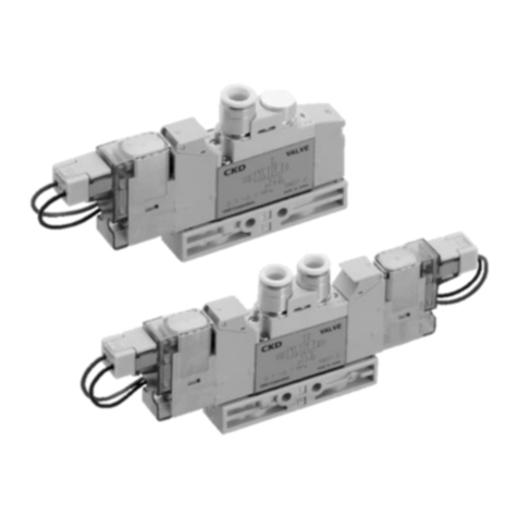
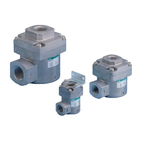
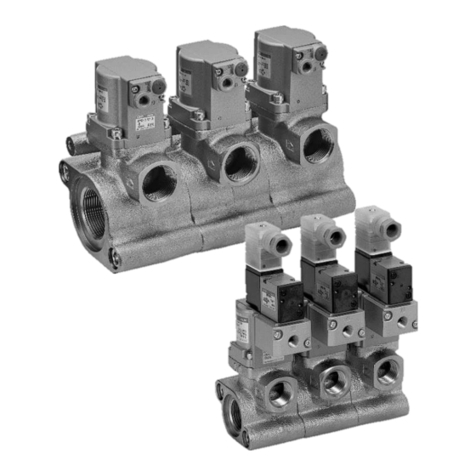
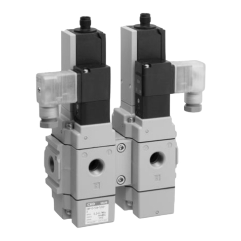
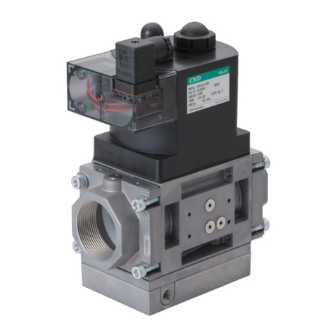
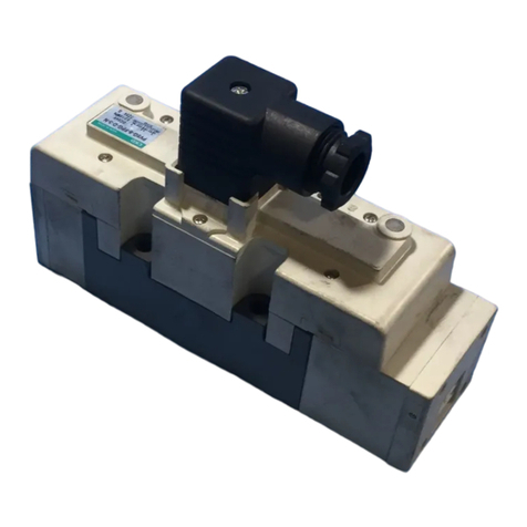
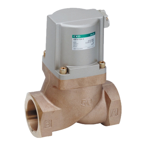
CKD USB2 Series User manual

SM-
SM-SM-
SM-5530
55305530
5530-A
-A-A
-A
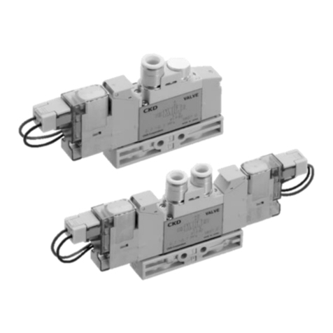
INSTRUCTION
INSTRUCTIONINSTRUCTION
INSTRUCTION MANUAL
MANUALMANUAL
MANUAL
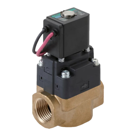
Compact direct acting solenoid valve
Compact direct acting solenoid valveCompact direct acting solenoid valve
Compact direct acting solenoid valve
USB
USBUSB
USB2
22
2 Series
Series Series
Series
USB
USBUSB
USB3
33
3 Series
Series Series
Series
USG
USGUSG
USG2
22
2 Series
Series Series
Series
USG
USGUSG
USG3
33
3 Series
Series Series
Series
Please
PleasePlease
Please
read
readread
read
this
thisthis
this
instruction
instructioninstruction
instruction
manual
manualmanual
manual
carefully
carefullycarefully
carefully
before
beforebefore
before
using
usingusing
using
this
thisthis
this
product,
product,product,
product,
particularly
particularlyparticularly
particularly
the
thethe
the
section
sectionsection
section
describing
describingdescribing
describing
safety
safetysafety
safety.
..
.
Retain
RetainRetain
Retain
this
thisthis
this
instruction
instructioninstruction
instruction
manual
manualmanual
manual
with
withwith
with
the
thethe
the
product
productproduct
product
for
forfor
for
further
furtherfurther
further
consultation
consultationconsultation
consultation
whenever
wheneverwhenever
whenever
necessary
necessarynecessary
necessary.
..
.
Ver.2

SM-
SM-SM-
SM-5530
55305530
5530-A
-A-A
-A
-1-
Safety precautions
When designing and manufacturing a device using CKD products, the manufacturer is
obligated to manufacture a safe product by confirming safety of the system comprising the
following items:
Device mechanism
Pneumatic or water control circuit
Electric control that controls the above
t is important to select, use, handle, and maintain the product appropriately to ensure that
the CKD product is used safely.
Observe warnings and precautions to ensure device safety.
Check that device safety is ensured, and manufacture a safe device.
1
11
1.
..
.This product is designed and manufactured as a general industrial machine
This product is designed and manufactured as a general industrial machine This product is designed and manufactured as a general industrial machine
This product is designed and manufactured as a general industrial machine
part.
part.part.
part.
t must be handled by someone having sufficient knowledge and
t must be handled by someone having sufficient knowledge and t must be handled by someone having sufficient knowledge and
t must be handled by someone having sufficient knowledge and
experience.
experience. experience.
experience.
2
22
2.
..
.Use this product within its specifications.
Use this product within its specifications.Use this product within its specifications.
Use this product within its specifications.
This product cannot be used beyond its specifications. Additionally, the product must not
be modified or machined.
This product is intended for use in general industrial devices and parts. Use beyond such
conditions is not considered. Consult with CKD for details when using the product
beyond the unique specification range, outdoors, or in the following conditions or
environments. n any case, measures for safety shall be provided when the vavle
malfunctions.
① Use for special applications requiring safety including nuclear energy, railroad,
aviation, ship, vehicle, medical equipment, equipment or applications coming into
contact with beverage or food, amusement equipment, emergency shutoff circuits,
press machine, brake circuits, or for safeguard.
② Use for applications where life or assets could be adversely affected, and special safety
measures are required.
3
33
3.
..
.Observe corporate standards and regulations, etc., related to the safety of
Observe corporate standards and regulations, etc., related to the safety of Observe corporate standards and regulations, etc., related to the safety of
Observe corporate standards and regulations, etc., related to the safety of
device design and control, etc.
device design and control, etc.device design and control, etc.
device design and control, etc.
SO4414, J S B 8370 (pneumatic system rules)
JFPS2008 (principles for pneumatic cylinder selection and use)
ncluding High Pressure Gas Maintenance Law, Occupational Safety and Sanitation
Laws, other safety rules, standards and regulations, etc.
4
44
4.
..
.Do not handle, pipe, or remove devices before confirming safety.
Do not handle, pipe, or remove devices before confirming safety.Do not handle, pipe, or remove devices before confirming safety.
Do not handle, pipe, or remove devices before confirming safety.
① nspect and service the machine and devices after confirming safety of the entire
system related to this product.
② Note that there may be hot or charged sections even after operation is stopped.
③ When inspecting or servicing the device, turn off the energy source (air supply or
water supply), and turn off power to the facility. Release any compressed air from the
system, and pay enough attention to possible water leakage and leakage of electricity.
④ When starting or restarting a machine or device that incorporates pneumatic
components, make sure that system safety, such as pop-out prevention measures, is
secured.
5
55
5.
..
.Observe warnings and cautions on the pages below to prevent accidents.
Observe warnings and cautions on the pages below to prevent accidents.Observe warnings and cautions on the pages below to prevent accidents.
Observe warnings and cautions on the pages below to prevent accidents.
WARNING
WARNINGWARNING
WARNING
SM-
SM-SM-
SM-5530
55305530
5530-A
-A-A
-A
-2-
■The safety cautions are ranked as "DANGER", "WARN NG" and "CAUT ON" in
■The safety cautions are ranked as "DANGER", "WARN NG" and "CAUT ON" in ■The safety cautions are ranked as "DANGER", "WARN NG" and "CAUT ON" in
■The safety cautions are ranked as "DANGER", "WARN NG" and "CAUT ON" in
this section.
this section.this section.
this section.
:
::
:When a dangerous situation may occur if handling is
mistaken leading to fatal or serious injuries, or when there is
a high degree of emergency to a warning.
:
::
:When a dangerous situation may occur if handling is
mistaken leading to fatal or serious injuries.
:
::
:When a dangerous situation may occur if handling is
mistaken leading to minor injuries or physical damage.
Note that some items described as "CAUT ON" may lead to serious results
depending on the situation. n any case, important information that must be
observed is explained.
Precautions
Precautions Precautions
Precautions with regard to guarantee
with regard to guaranteewith regard to guarantee
with regard to guarantee
Guarantee period
Guarantee periodGuarantee period
Guarantee period
The guarantee period of our product shall be one (1) year after it is delivered to the place
specified by the customer.
Guarantee coverage
Guarantee coverageGuarantee coverage
Guarantee coverage
f any failure for which CKD CORPORAT ON is recognized to be responsible occurs within
the above warranty period, a substitute or necessary replacement parts shall be provided
free of charge, or the product shall be repaired free of charge at the plant of CKD
CORPORAT ON.
However, the guarantee excludes following cases:
① Defects resulting from operation under conditions beyond those stated in the catalogue or
specifications.
② Failure resulting from malfunction of the equipment and/or machine manufactured by
other companies.
③ Failure resulting from wrong use of the product.
④ Failure resulting from modification or repairing that CKD CORPORAT ON is not
involved in.
⑤ Failure resulting from causes that could not be foreseen by the technology available at
the time of delivery.
⑥ Failure resulting from disaster that CKD is not responsible of.
Guarantee stated here covers only the delivered products. Any other damage resulting from
failure of the delivered products is not covered by this guarantee.
Confirmation of product compatibility
Confirmation of product compatibilityConfirmation of product compatibility
Confirmation of product compatibility
Our customer shall be responsible of confirming compatibility of our product used in our
customer’s system, machinery or device.
DANGER
DANGERDANGER
DANGER
WARNING
WARNINGWARNING
WARNING
CAUTION
CAUTIONCAUTION
CAUTION

SM-
SM-SM-
SM-5530
55305530
5530-A
-A-A
-A
-3-
【
【【
【
Contents
ContentsContents
Contents
】
】】
】
1
11
1.
..
.Unpacking
UnpackingUnpacking
Unpacking
……………………………………………………… 4
2
22
2.
..
.nstallation
nstallationnstallation
nstallation
2.1 Conditions for installation ………………………………… 4
2.2 nstallation method ………………………………………… 4
2.3 Piping ……………………………………………………… 5
2.4 Wiring ……………………………………………………… 7
3
33
3.
..
.Pre
PrePre
Pre-
--
-operation (post
operation (postoperation (post
operation (post-
--
-installation) check
installation) checkinstallation) check
installation) check
3.1 Appearance check …………………………………………… 8
3.2 Leakage check………………………………………………… 8
3.3 Electrical check ……………………………………………… 8
3.4 Operation check ……………………………………………… 8
4
44
4.
..
.nstructions
nstructions nstructions
nstructions for proper use
for proper usefor proper use
for proper use
4.1 Handling precautions………………………………………… 9
5
55
5.
..
.Maintenance
MaintenanceMaintenance
Maintenance
5.1 Maintenance and inspection………………………………… 10
5.2 Parts for maintenance ……………………………………… 10
6
66
6.
..
.Troubleshooting
TroubleshootingTroubleshooting
Troubleshooting
………………………………………………………… 11
7
77
7.
..
.Appropriate disposal
Appropriate disposalAppropriate disposal
Appropriate disposal
………………………………………………… 11
8
88
8.
..
.nternal construction
nternal constructionnternal construction
nternal construction
8.1 nternal construction of the 2-port valve ………………… 12
8.2 nternal construction of the 3-port valve ………………… 14

SM-
SM-SM-
SM-5530
55305530
5530-A
-A-A
-A
-4-
1.Unpacking
Do not take off the port protection until just before piping.
Otherwise, foreign matter enters the valve and cause
malfunction or bad operation.
(1)
Check that the model No. shown on the name plate of the product is the same with
what you ordered.
(2)
Check that the product has no external damages.
(3)
When storing the product, keep the product inside the packing box to prevent the
intrusion of foreign matter to the valve. Take out the valve when piping.
2. nstallation
Contact CKD if the product is to be used beyond
specifications, or in special applications.
2.1 Conditions for installation
a) Do not splash liquid such as water or lubricating oil.
Otherwise, liquid splashed on the coil causes the coil to
burn.
Protective measure shall be taken against welding
spatter.
b) The coil generates heat.
・ f the product is to be installed inside a control panel,
or if energizing time is long, provide ventilation
measures. Temperature around the product will be
high.
c) The product can not be used in a corrosive or solvent
environment.
d) Avoid humid environments, since condensation may occur
with change in temperature.
e) The product cannot be used in an explosive gas
atmosphere.
f) Use the product away from radiant heat.
(1) Provide appropriate measures to prevent the product from freezing at cold places.
(2) The product cannot be used outdoors. Protective measure shall be taken such as
covering, or valve installation inside a panel.
(3)
Do not wash the product with water or solvents. Do not paint the product. Resin
material used in the product may break down.
(4)
Do not use the product under vibration or inertia.
2.2 nstallation method
a) Read this instruction manual thoroughly and understand
the contents before installing the product.
b) Always take hold of the body portion when handling and
mounting the product.
c) Confirm leakage from the piping after installation.
CAUTION
CAUTIONCAUTION
CAUTION
WARNING
WARNINGWARNING
WARNING
WARNING
WARNINGWARNING
WARNING
CAUTION
CAUTIONCAUTION
CAUTION

SM-
SM-SM-
SM-5530
55305530
5530-A
-A-A
-A
-5-
(1)
Mounting posture is unrestricted.
However, avoid positioning the coil side down, since foreign matter in the fluid
accumulates around the plunger and result in beat sounds and malfunction.
(2)
Provide enough space for safe maintenance and troubleshooting work.
2.3 Piping method
a) When piping or re-piping, fix the product.
b) Fix and provide appropriate support to the piping, so that
the weight and vibration of the piping will not directly be
applied to the product.
c) When piping is finished and fluid is to be flown, supply
pressure gradually.
・f the piping is improper, the piping may disconnect or
the fluid may leak.
(1)
Cleaning the piping
・
Before piping, flush the piping with compressed air 0.3MPa or more to remove
foreign material such as dust, metal powder, rust and sealing material.
(2)
Removal of foreign matter
・
Foreign matter such as dust in the fluid causes malfunction and leakage.
To remove foreign matter, attach an appropriate apparatus to the primary side of
the product. When the fluid is air, attach a filter 5µm or finer. When the fluid is
water, attach a strainer 80 mesh or finer.
(3)
Piping
・
Make sure that the piping port is correct.
f the supply port is not clear, refer to the product model number and the J S
symbol in the catalogue.
・When piping to the normally open (NO) side Socket for metal body USG3, fix the Socket
with a tool such as an adjustable spanner when
tightening.
・For resin body types, do not use a metal connector (M6),
since it may break the port.
Use a connector made from
polypropylene resin (PP) or
fluorine resin (PTFE, PFA) (Refer to figure 1.).
When body material is
PPS resin
(Figure 1.) Resin body type
Use a M6 connector
made from resin
CAUTION
CAUTIONCAUTION
CAUTION

SM-
SM-SM-
SM-5530
55305530
5530-A
-A-A
-A
-6-
・When piping a tube to a barbed joint, be sure to insert the tube
straightforward.
Choose tube that has inner diameter around φ4.
Confirm leakage and connection firmness before work, since
attaching force (retaining force) differs according to tube
material.
Do not apply excessive force such as pull, compression, and
bending after piping. External force of 0.2 N・ m or more
applied to the barbed joint causes leakage or breakage.
(4)
Sealing material
・
When using sealing material, make sure the sealing material do not enter the
piping. Also, make sure there is no external leakage. When taping seal tape to the
pipe thread, leave 1 to 2 threads at the tip without taping.
Also, when using liquid sealing material, leave 1 to 2 threads at the tip without
sealing material. Do not apply too much sealing material on the thread. Do not
apply sealing material to the internal thread (refer to figure 2.).
●
Seal tape
●Solid or liquid sealing material
(良) (悪) (良) (悪)
(Figure 2.) How to apply sealing material
(5) Tightening
・
Refer to table 1. for the recommended port tightening torque.
Table 1.Recommended port tightening torque
(6)
Lubricated or non-lubricated operation
・
This product does not require lubrication. Therefore, no lubricator is needed.
f the product is to be lubricated, use turbine oil Class 1, SO VG32 (#90) or
equivalent. Once lubricated, do not stop periodical lubrication.
Body material Port size
Recommended torque
M5 1.0 to 1.5 N・m
Copper alloy or
stainless steel Rc1/8 18 to 20 N・m
PPS resin M6 0.1 to 0.15 N・m
残す
1~ 2山
シール剤
液状
固形
液状
固形
シール剤
(Good)
(Bad)
Leave 1 to
2 threads
(Good)
(Bad)

SM-
SM-SM-
SM-5530
55305530
5530-A
-A-A
-A
-7-
2.4 Wiring
Read this instruction manual thoroughly and understand the
contents before wiring the product.
・You need to understand the structure and the operation
principle of the solenoid valve. You additionally need
knowledge to secure safety.
a) Confirm the voltage and the alternating or direct current
type.
b) To prevent unintended operation caused by electric
leakage of other control components, confirm electric
leakage.
・When using a control circuit such as a programmable
controller, the solenoid valve may operate without
intention because of the electric leakage from the
control components.
・When using this product, keep the electric leakage
from other components below the value shown in the
table below.
Rated voltage Electric leakage
DC12V 2mA or less
DC24V 1mA or less
AC100V coil with built-in diode 0.2mA or less
AC200V coil with built-in diode 0.1mA or less
(1)
Maintenance of the electric equipment
・
To maintain the electric equipment, install a breaker such as a fuse in the control
circuit side.
(2)
Wiring of the lead wire type
・
For wiring, use wire with nominal cross-sectional area 0.5mm2
or larger. Additionally,
take care not to apply too much force on the lead wire.
There is no polarity for DC coils.
CAUTION
CAUTIONCAUTION
CAUTION
CAUTION
CAUTIONCAUTION
CAUTION
C
R
回
路
電
流
漏
洩
電
磁
弁
コ
ン
ト
ロ
ー
ル
側
プ
ロ
グ
ラ
マ
ブ
ル
ト
ラ
イ
ア
ッ
ク
CR circuit
Programmable
controller side
Solenoid
valve
Electric
leakage
Triac

SM-
SM-SM-
SM-5530
55305530
5530-A
-A-A
-A
-8-
3.Pre-operation (post-installation) check
3.1 Appearance check
(1)
Push the product by hand and confirm that the product is firmly fixed on the piping.
(2)
Confirm that threaded parts such as bolts, nuts and screws are not loose.
3.2 Leakage check
(1)
Confirm leakage at the connection part by applying pressure to the fluid.
We recommend leakage check by the following method:
・ Supply compressed air (0.1-0.3 MPa)
・ Apply soap water to the portion to check for leakage
・ Bubbles will appear if there is any leakage.
3.3 Electrical check
Cut off the electricity.
Check while taking serious care to avoid electric shock.
(1)
Check the supply voltage.
Voltage variation shall be within 10% of the rated voltage.
Use beyond the allowed variation range will cause malfunction or damage to the coil.
(2)
Check insulation resistance
Check the insulation resistance between dead metal parts and uninsulated live parts
(such as the tip of the lead wire) that are assembled to the product.
Confirm that insulation resistance is over 100MΩ at DC500V megger.
3.4 Operation check
(1)
Apply rated voltage to the valve and rated pressure to the working fluid. Confirm
normal operation of the product.
Stop the flow of the fluid (shut the supply) .
Discharge the fluid inside the product.
WARNING
WARNINGWARNING
WARNING
WARNING
WARNINGWARNING
WARNING
SM-
SM-SM-
SM-5530
55305530
5530-A
-A-A
-A
-9-
4. nstructions for proper use
4.1 Handling precautions
a) Do not use this product as an emergency shut-off valve.
・ This product is not designed as a safety-securing valve,
such as an emergency shut-off valve. For such systems,
use this valve after providing another method to secure
safety.
b) Take measures to prevent harm to operators or objects if
this product fails.
c) Liquid-filled state
・ When conveying a liquid in a circuit, operation may
fail if liquid-filled state occurs. This is because
pressure rises in the liquid-filled state when
temperature rises. Provide an escape valve in the
system so that a liquid-filled state circuit is not
created.
d) Working fluids
・ Do not use this product for fluids other than the
working fluids listed in the catalog specifications.
・ Before use, confirm the compatibility of the product
and applicable fluid with the Applicable Fluid Check
List.
・ Depending on the model, internal parts may wear
when the valve operates. Caution is required because
wear chips could enter the secondary side of the valve.
a) Do not touch the coil sections or actuator sections when
energized or immediately after energizing. Depending on
the product, directly touching these products could cause
burns.
b) Do not touch the wiring connection sections (bare live
part) when energized. There is a risk of electric shock.
c) Always use within the maximum working pressure and
maximum working pressure differential range.
(1)
When carrying the solenoid valve, hold the main body.
Do not carry the valve by the lead wire.
(2)
Do not use the product as footings, or place heavy loads on the product.
(3)
f the product has not been used for more than a month, the seal rubber and metal at
the valve seat may stick and delay operation. Carry out trial run in such cases.
(4) f the 3-port valve (Model: USG) is to be energized continuously, select fluororubber
sealing.
(5)
f the fluid is dry air or inert gas, number of duration cycles decrease significantly
due to abrasion. Please contact us in these cases.
(6)
This product cannot be used for vacuum holding. Please contact us if the intended
usage is vacuum holding.
(7)
Fluid viscosity shall be 50 mm
2
/s or less. Otherwise, the product will malfunction.
(8)
Refer to “6. Troubleshooting” if any trouble occur.
WARNING
WARNINGWARNING
WARNING
CAUTION
CAUTIONCAUTION
CAUTION

SM-
SM-SM-
SM-5530
55305530
5530-A
-A-A
-A
-10-
5.Maintenance
5.1 Maintenance and inspection
a) Read this nstruction manual thoroughly and
understand the contents well before performing
maintenance and inspection.
b) Shut off the power supply and release the fluid pressure
before performing maintenance.
(1)
Regularly inspect the product to ensure optimum performance. Although inspection
frequency differs based on the working state, the product should be inspected every
half year.
(2)
Refer to “3. Pre-operation check” for contents of inspection.
(3)
When washing the parts, use a washing agent with low environmental impact, such
as a neutral detergent. Note that the rubber parts must be replaced as they could
expand.
(4)
When not using the product for one or more months after passing water or hot water,
completely remove any water or hot water left in the product. Water or hot water
residue will cause rust and may lead to operation failure or leaks.
(5)
Please contact CKD if there are any unclear points concerning consumable parts.
(6)
Beware the clogging of the strainer and filter.
(7)
When the product is disassembled and reassembled, tighten the threaded parts with
torque shown in Table 2.
Table 2. Recommended tightening torque of threaded parts
Model Core B Socket Cross Recessed Pan
Head Machine
Screw with Washer
USB2・USG2
Metal body
10 to 22 N・m - -
USB3・USG3
Metal body
18 to 32 N・m 4 to 8 N・m -
USB2・USG2
Resin body
- - 0.27 to 0.33 N・m
USB3・USG3
Resin body
- - 0.27 to 0.33 N・m
5.2 Parts for Maintenance
(1) O ring
Replace when the valve leaks while use, or at disassembly and reassembly.
(2) Plunger Assembly, Spring
Replace when the valve shows abnormality such as leak or malfunction.
CAUTION
CAUTIONCAUTION
CAUTION

SM-
SM-SM-
SM-5530
55305530
5530-A
-A-A
-A
-11-
6.Troubleshooting
(1)
f the solenoid valve does not operate as intended, check according to tables 3. and 4.
Table 3.
Cause of malfunction and countermeasures for 2-port valves(Model: USB2, USB3)
State of failure Cause Countermeasure
Valve is not energized. Confirm wiring and fuse, then
energize the valve.
Voltage applied is lower than the
allowable voltage range.
Confirm the power supply, and apply
rated voltage.
Fluid does not
flow
Applied fluid pressure is too high.
Set pressure within allowable range.
Wrong port is connected to the high
pressure side.
Pipe correctly.
Electricity is not shut off.
Check for leak of electricity. Modify the
circuit to cut off electricity completely.
Fluid does not
stop flowing
Plunger does not move because
foreign matter is caught in.
Disassemble and remove foreign
matter.
Abrasion or flaw of packing and O
ring.
Replace parts.
Valve leaks
externally
Core B is loose. Tighten the Core B.
The valve seat of the Body is worn or
damaged.
Replace the product.
Abrasion or flaw of the sealing side
of the rubber parts.
Replace parts.
Valve leaks
internally
Foreign matter caught in the valve
seat.
Disassemble and remove foreign matter.
Table 4.
Cause of malfunction and countermeasures for 3-port valves(Model: USG2, USG3)
State of failure Cause Countermeasure
Valve is not energized. Confirm wiring and fuse, then
energize the valve.
Voltage applied is lower than the
allowable voltage range.
Confirm the power supply, and apply
rated voltage.
Fluid does not
flow
Applied fluid pressure is too high.
Set pressure within allowable range.
Wrong port is connected to the high
pressure side.
Pipe correctly.
Electricity is not shut off.
Check for leak of electricity. Modify the
circuit to cut off electricity completely.
Fluid does not
stop flowing
Plunger does not move because
foreign matter is caught in.
Disassemble and remove foreign
matter.
Abrasion or flaw of packing and O
ring.
Replace parts.
Valve leaks
externally
Core B or Socket is loose. Tighten the Core B or Socket.
The valve seat of the Body is worn or
damaged.
Replace the product.
Abrasion or flaw of the sealing side
of the rubber parts.
Replace parts.
Valve leaks
internally
Foreign matter caught in the valve
seat.
Disassemble and remove foreign matter.
(2) Please contact CKD or your nearest agent for any unclear points.
7.Appropriate disposal
(1) When disposing this product, dispose this product as industrial waste.
(2) This valve series includes coil types that uses lead wires insulated by PVC covering. Do
not burn this product at disposal, since deleterious chlorine gas emits when PVC is
burned.

SM-
SM-SM-
SM-5530
55305530
5530-A
-A-A
-A
-12-
8. nternal construction
8.1 nternal construction of the 2-port valve
(1) Model:USB2 (Metal body)
Note) Consumable parts kit is available for replacement.
(2) Model:USB3 (Metal body)
Note) Consumable parts kit is available for replacement.
No. Part name Remarks
①
Clip
②
Auxiliary Core
③
Bonnet
④
Core Assembly
⑤
Coil Assembly
⑥
Plunger Assembly Consumable part
⑦
Waving Washer
⑧
Core B
⑨
O ring Consumable part
⑩
Spring Consumable part
⑪
Body
No. Part name Remarks
①
Clip
②
Bonnet Piece
③
Bonnet
④
Core Assembly
⑤
Coil Assembly
⑥
Plunger Assembly Consumable part
⑦
nsulating Film
⑧
Waving Washer
⑨
Core B
⑩
O ring Consumable part
⑪
Spring Consumable part
⑫
Body

SM-
SM-SM-
SM-5530
55305530
5530-A
-A-A
-A
-13-
(3) Model:USB2 (Resin body)
(4) Model:USB3 (Resin body)
No. Part name Remarks
①
Clip
②
Auxiliary Core
③
Core Assembly
④
Bonnet
⑤
Stamp Label
⑥
Plunger Assembly Consumable part
⑦
Coil Assembly
⑧
Waving Washer
⑨
O ring Consumable part
⑩
Spring Consumable part
⑪
Core B
⑫
Body
⑬
Body Holding Board
⑭
Cross Recessed Pan
Head Machine
Screw with Washer
No. Part name Remarks
①
Clip
②
Bonnet
③
Bonnet Piece
④
Core Assembly
⑤
Coil Assembly
⑥
Stamp Label
⑦
Plunger Assembly Consumable part
⑧
Waving Washer
⑨
Auxiliary Core
⑩
Cross Recessed Pan
Head Machine
Screw with Washer
⑪
Core B
⑫
O ring Consumable part
⑬
Spring Consumable part
⑭
Body
⑮
Body Holding Board
Note) Consumable parts kit is available for replacement.

SM-
SM-SM-
SM-5530
55305530
5530-A
-A-A
-A
-14-
8.2 nternal construction of the 3-port valve
(1) Model:USG2 (Metal body)
Note) Consumable parts kit is available for replacement.
(2) Model:USG3 (Metal body)
Note) Consumable parts kit is available for replacement.
No.
Part name Remarks
①
Clip
②
Auxiliary Core
③
Bonnet
④
Core Assembly
⑤
Coil Assembly
⑥
Plunger Assembly Consumable part
⑦
Waving Washer
⑧
Core B
⑨
O ring Consumable part
⑩
Spring Consumable part
⑪
Body
No.
Part name Remarks
①
Socket
②
O ring Consumable part
③
Washer
④
Bonnet Piece
⑤
Bonnet
⑥
Core Assembly
⑦
Coil Assembly
⑧
Plunger Assembly Consumable part
⑨
nsulating Film
⑩
Waving Washer
⑪
Core B
⑫
O ring Consumable part
⑬
Spring Consumable part
⑭
Body

SM-
SM-SM-
SM-5530
55305530
5530-A
-A-A
-A
-15-
(3) Model:USG2 (Resin body)
(4) Model:USG3 (Resin body)
No. Part name Remarks
①
Clip
②
Auxiliary Core
③
Core Assembly
④
Bonnet
⑤
Name Plate
⑥
Plunger Assembly Consumable part
⑦
Coil Assembly
⑧
Waving Washer
⑨
O ring Consumable part
⑩
Core B
⑪
Spring
⑫
Body
⑬
Body Holding Board
⑭
Cross Recessed Pan
Head Machine
Screw with Washer
No.
Part name Remarks
①
Clip
②
Bonnet
③
Bonnet Piece
④
Core Assembly
⑤
Coil Assembly
⑥
Name Plate
⑦
Plunger Assembly Consumable part
⑧
Waving Washer
⑨
Auxiliary Core
⑩
Cross Recessed Pan
Head Machine
Screw with Washer
⑪
Core B
⑫
O ring Consumable part
⑬
Spring Consumable part
⑭
Body
⑮
Body Holding Board
Note) Consumable parts kit is available for repla
cement.
Note) Consumable parts kit is available for replacement.
This manual suits for next models
3
Table of contents
Other CKD Control Unit manuals

CKD
CKD M3GA/B R Series User manual

CKD
CKD FWD Series User manual

CKD
CKD 3KA1 User manual

CKD
CKD 4KA2 User manual

CKD
CKD GCVE2 Series User manual

CKD
CKD 3GD/E1 Series User manual

CKD
CKD MN3GD/E1 Series User manual

CKD
CKD M4GA4-T6G1 User manual

CKD
CKD NP13 Series User manual

CKD
CKD CVE2 Series Installation and operating manual
Popular Control Unit manuals by other brands

Stahl
Stahl 9172 Series operating instructions

Aventics
Aventics CONTROLAIR H-1 Service information

Lawler
Lawler 4000 Series Installation & maintenance manual

Würth
Würth 0978 950 006 Quick installation guide

Texas Instruments
Texas Instruments SimpleLink CC3200MOD manual

Roger
Roger EDGE1 Series Instruction and warnings for the installer