Adnacom AUS324 User manual


AUS324 User’s Guide
Rev. 1.0
Adnacom Inc.
2 of 34
https://adnacom.com/
Contents
User’s Guide.......................................................................................................................................................................................... 1
1Terminology............................................................................................................................................................................... 4
2Applicable and Reference Documents............................................................................................................................ 5
2.1 Reference Documents..................................................................................................................................................... 5
2.2 Applicable Documents.................................................................................................................................................... 5
3System Description ................................................................................................................................................................. 6
3.1 Overview............................................................................................................................................................................... 6
3.2 Recommended Transceivers and Cables................................................................................................................. 7
3.2.1 Active Optical Cables ............................................................................................................................................ 7
3.2.2 Optical Transceivers............................................................................................................................................... 7
3.2.3 LC-LC Cables............................................................................................................................................................. 7
4System Operation.................................................................................................................................................................... 8
4.1 USB Bandwidth Allocation ............................................................................................................................................ 8
4.2 USB324 Power Control Modes.................................................................................................................................... 8
5System Installation .................................................................................................................................................................. 9
5.1 Installation Recommendations.................................................................................................................................... 9
5.2 Preparing Your Computer ............................................................................................................................................. 9
5.3 Installing the H14 or H18 Host Adapter Card....................................................................................................... 9
5.4 Installing the USB324 Unit ............................................................................................................................................ 9
5.5 Installing QSFP Transceivers and Connecting Fiber Optic Cables ................................................................ 9
5.6 Turning on the System for the First Time ............................................................................................................... 9
5.7 Connecting USB Devices..............................................................................................................................................10
6System Functionality Verification ....................................................................................................................................11
7H14 PCIe Host Adapter .......................................................................................................................................................13
7.1 H14 Drawing .....................................................................................................................................................................13
7.2 H14 Cable Interface .......................................................................................................................................................13
7.3 H14 S1 DIP Switch Description..................................................................................................................................14
7.4 H14 LEDs Description....................................................................................................................................................14
8H18 PCIe Host Adapter .......................................................................................................................................................16
8.1 H18 Drawing .....................................................................................................................................................................16
8.2 H18 Cable Interface .......................................................................................................................................................16
8.3 H18 S1 DIP Switch Description..................................................................................................................................16
8.4 H18 LEDs Description....................................................................................................................................................17
8.5 H18 Connectors Description ......................................................................................................................................18
9USB324 Remote Unit............................................................................................................................................................19

AUS324 User’s Guide
Rev. 1.0
Adnacom Inc.
3 of 34
https://adnacom.com/
9.1 USB324 Drawings............................................................................................................................................................19
9.2 USB324 Connectors .......................................................................................................................................................19
9.3 USB324 LEDs Description ............................................................................................................................................20
9.4 USB324 DIP Switch Description ................................................................................................................................20
9.5 USB324 Mechanical .......................................................................................................................................................21
9.5.1 USB324 Dimensions ............................................................................................................................................21
9.5.2 Wall Mounting Brackets.....................................................................................................................................22
10 Web Interface..........................................................................................................................................................................23
10.1 Overview.............................................................................................................................................................................23
10.2 IP Address Configuration.............................................................................................................................................23
10.2.1 Default IP Address: S1.8 = OFF .......................................................................................................................23
10.2.2 User’s IP Address: S1.8 = ON...........................................................................................................................23
10.3 H18 Web Site IP: 192.168.100.101 ...........................................................................................................................25
10.3.1 Overview ..................................................................................................................................................................25
10.3.2 Status Page .............................................................................................................................................................25
10.3.2.1 Configuration ...........................................................................................................................................25
10.3.2.2 Status...........................................................................................................................................................26
11 Troubleshooting.....................................................................................................................................................................29
11.1 Overview.............................................................................................................................................................................29
11.2 System Context Diagram .............................................................................................................................................29
11.3 Troubleshooting Algorithm ........................................................................................................................................29
11.3.1 Identify Problem ...................................................................................................................................................29
11.3.2 Review Operating and Installation Instructions.......................................................................................30
11.3.3 Verify Computer and USB Devices ................................................................................................................30
11.3.4 Verify Host Adapter.............................................................................................................................................30
11.3.5 Verify QSFP Cable.................................................................................................................................................30
11.3.6 Verify USB324 Unit...............................................................................................................................................30
11.3.7 Verify USB Devices ...............................................................................................................................................31
12 Products Design Disclaimer...............................................................................................................................................32
13 Customer Support .................................................................................................................................................................33
14 Warranty....................................................................................................................................................................................34

AUS324 User’s Guide
Rev. 1.0
Adnacom Inc.
4 of 34
https://adnacom.com/
1Terminology
Table 1-1. Common Terms Used in the User’s Guide.
Term
Description
AOC
Active optical cable
xN
A PCIe link with “N” lanes
EMI
Electromagnetic Interference
ESD
Electrostatic Discharge
Gbps
Gigabit per second
Gb/s
Gigabit per second
PCIe Gen 3
PCIe 8 GT/s
PCIe Lane
A set of differential signal pairs, one pair for transmission and one pair for
reception
LC
LC stands for Lucent Connector. The LC is a small form-factor fiber optic
connector.
PCIe Link
The collection of two ports and their interconnecting lanes. A link is a dual-
simplex communications path between two components.
NC
Not connected
OS
Operating system
PCIe
Interconnect standard for PCI Express cards
QSFP
Quad Small Form-factor Pluggable
RMA
Return Material Authorization
USB 3.2 Gen 1
The nominal signaling data rate for the Gen 1 physical layer is 5 Gbps
USB 3.2 Gen 2
The nominal signaling data rate for the Gen 2 physical layer is 10 Gbps

AUS324 User’s Guide
Rev. 1.0
Adnacom Inc.
5 of 34
https://adnacom.com/
2Applicable and Reference Documents
2.1 Reference Documents
RD-1: H14 Datasheet. Adnacom Inc., https://adnacom.com.
RD-2: H18 Datasheet. Adnacom Inc., https://adnacom.com.
RD-3: AUS324 Datasheet. Adnacom Inc., https://adnacom.com.
2.2 Applicable Documents
AD-1: Universal Serial Bus 3.2 Specification, Revision 1.0. USB-IF, https://usb.org/.
AD-2: PCI Express Base Specification, Revision 3.0. PCI-SIG, https://pcisig.com.
AD-3: SFF-8436. QSFP+ 4x 10 Gb/s Pluggable Transceiver, Revision 4.9. SFF Committee.
AUS324 User’s Guide
Rev. 1.0
Adnacom Inc.
6 of 34
https://adnacom.com/
3System Description
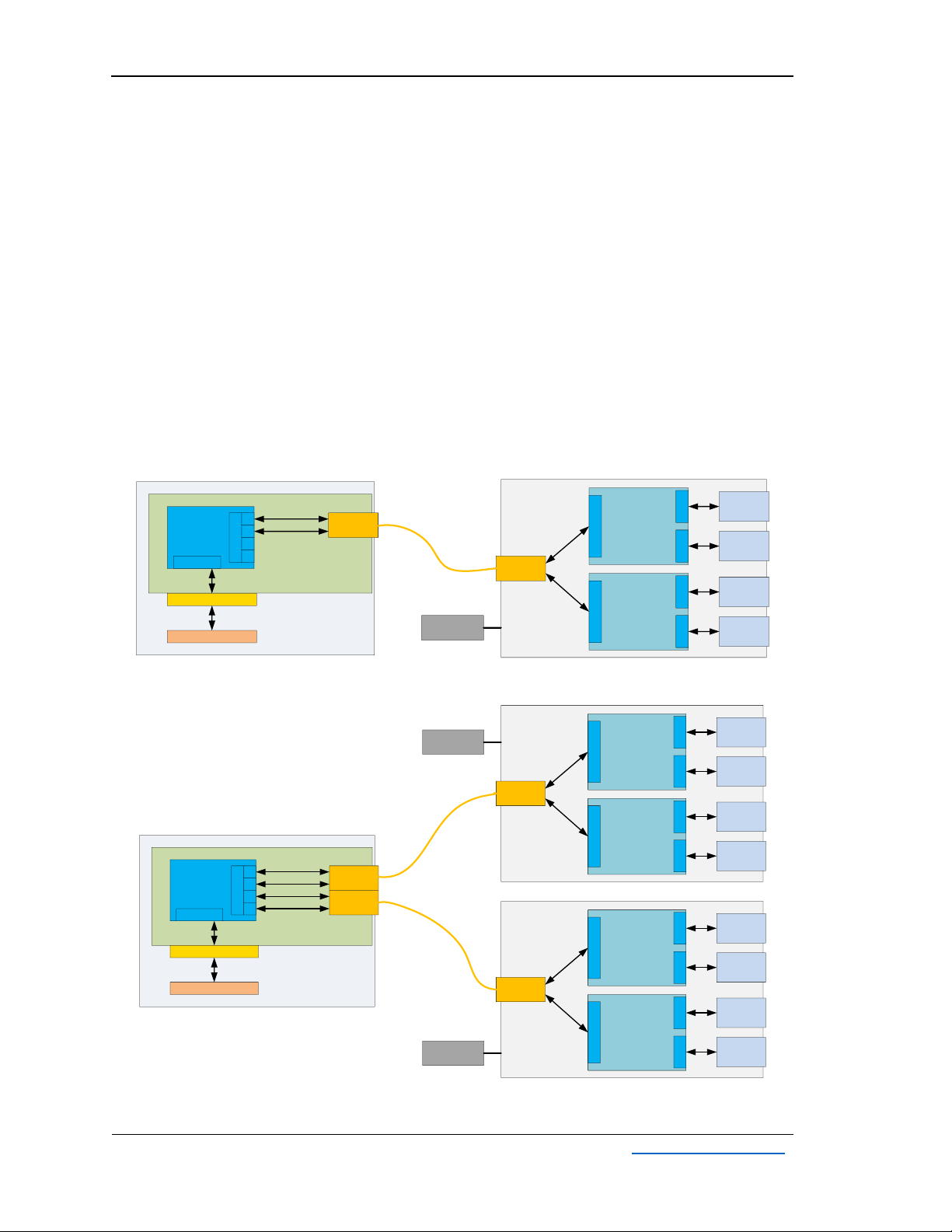
3.1 Overview
The Adnacom AUS324 is a USB 3.2 Gen 2 extender that supports USB 3.2 Gen 2 (10 Gb/s) and Gen
1 (5 Gb/s), 2.0, and 1.1 devices. The system consists of an Adnacom PCIe host adapter and a
USB324 remote unit connected by a fiber optic cable. The system uses a PCIe bus extension over
a fiber-optic cable and standard USB host controllers located in the remote unit. The remote unit
contains 2 AsMedia ASM3142 USB 3.2 Gen 2 host controllers and a PCIe fiber-optic interface. The
system is intended for high-performance USB applications and utilizes the full bandwidth of 2
ASM3142 controllers. The system can operate with QSFP transceivers or active optical cables
(AOCs). The H14 host adapter interfaces one USB324 unit. The H18 host adapter can interface
one or two USB324 units. The system diagrams are shown in Figure 3-1 and Figure 3-2.
Figure 3-1. AUS324 with H14 Host Adapter.
Figure 3-2. AUS324 with H18 Host Adapter.
PCIe Port 1
Lanes 0-1
16 Gb/s
USB324
QSFP 1
AsMedia
ASM3142
USB 3.2 Gen 2
Host Controller
2
PCIe Gen 3 x2
USB
Connector
3
Port 2
USB
Connector
4
PCIe Port 2
Lanes 0-1
16 Gb/s
Port 1
AsMedia
ASM3142
USB 3.2 Gen 2
Host Controller
1
PCIe Gen 3 x2
USB
Connector
1
Port 2
USB
Connector
2
Port 1
1
PCIe Gen 3
Switch
PCIe Gen 3 x4
32 Gb/s
PCIe 4x, x8 or x16 slot COMPUTER
PCIe Lanes 0-1
QSFP 1
H14
PCIe x4
PCIe Ports
Port 0
2
4
5
PCIe Lanes 0-1
Power Supply
5V, 8A
1
PCIe Gen 3
Switch
PCIe Gen 3 x8
64 Gb/s
PCIe x8 or x16 slot COMPUTER
PCIe Lanes 0-1
QSFP 1
H18
PCIe x8
PCIe Ports
Port 0
2
4
5
PCIe Lanes 0-1
PCIe Lanes 0-1
QSFP 2
PCIe Lanes 0-1
PCIe Port 1
Lanes 0-1
16 Gb/s
USB324
QSFP 1
AsMedia
ASM3142
USB 3.2 Gen 2
Host Controller
2
PCIe Gen 3 x2
USB
Connector
3
Port 2
USB
Connector
4
PCIe Port 2
Lanes 0-1
16 Gb/s
Port 1
AsMedia
ASM3142
USB 3.2 Gen 2
Host Controller
1
PCIe Gen 3 x2
USB
Connector
1
Port 2
USB
Connector
2
Port 1
PCIe Port 4
Lanes 0-1
16 Gb/s
USB324
QSFP 1
AsMedia
ASM3142
USB 3.2 Gen 2
Host Controller
2
PCIe Gen 3 x2
USB
Connector
3
Port 2
USB
Connector
4
PCIe Port 5
Lanes 0-1
16 Gb/s
Port 1
AsMedia
ASM3142
USB 3.2 Gen 2
Host Controller
1
PCIe Gen 3 x2
USB
Connector
1
Port 2
USB
Connector
2
Port 1
Power Supply
5V, 8A
Power Supply
5V, 8A
AUS324 User’s Guide
Rev. 1.0
Adnacom Inc.
7 of 34
https://adnacom.com/
3.2 Recommended Transceivers and Cables
For information on tested cable lengths and measured data transfer rates, please visit the
AUS324 product webpage: https://adnacom/aus324/.
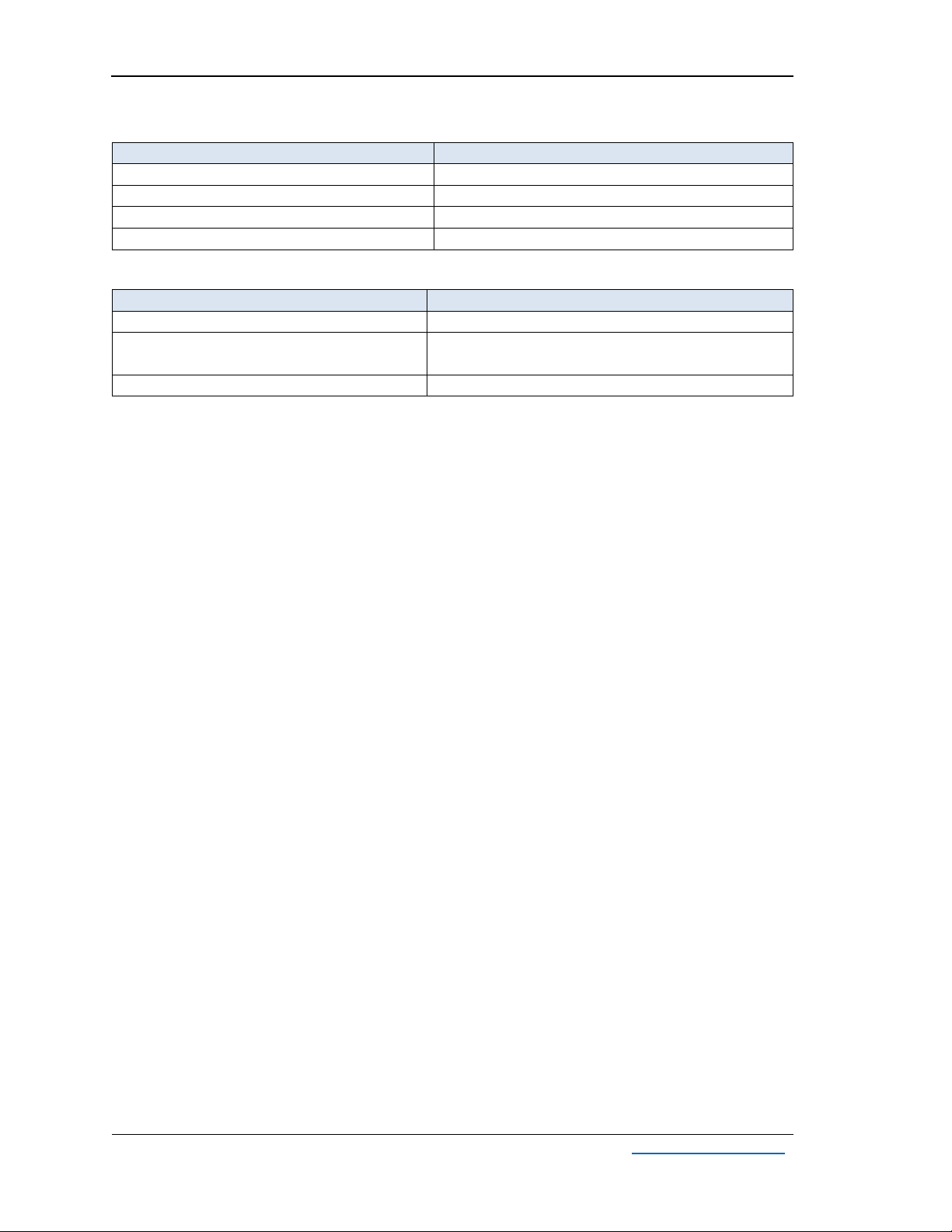
3.2.1 Active Optical Cables
Table 3-1. Tested AOC.
Manufacturer
Part Number
Description
Finisar
FCCN410QD3C10
Reliable operation
Fiber Store
QSFP-AO10
Reliable operation
Others
Some cables may not work reliably. Other cables must be
tested before using them in the production environment.
3.2.2 Optical Transceivers
The AUS324 can operate with standard multimode and single mode QSFP transceivers. The
transceivers should consume less than 1.5 W to keep their temperature within recommended
operating conditions. If transceivers consume more than 1.5 W, heatsinks should be installed on
the QSFP cages. The transceiver’s power consumption and case temperature can be verified using
the web interface described in section 9.
Table 3-2. Tested Transceivers.
Manufacturer
Part Number
Description
Finisar
FTL4C1QL2C
Reliable operation
Fiber Store
QSFP-LX4-40G
Reliable operation
10Gtek
ALQ10-IR4-02
ALQ10-LR4-10
Reliable operation
3.2.3 LC-LC Cables
Multimode and single mode LC-LC duplex cables can be used with single mode QSFP transceivers
with LC connectors. The QSFP transceivers multiplex and demultiplex 4 PCIe Gen 3 lanes into a
single LC-LC duplex cable using Coarse Wavelength Division Multiplexing (CWDM). A single LC-LC
duplex cable supports a 32 Gb/s data rate. The recommended multimode cable types are OM3
and OM4. The recommended maximum cable lengths for different cable types are shown in Table
3-3. System performance depends on the cable length. For further information, visit
https://adnacom.com/aus324/.
Table 3-3. Recommended Maximum Length for LC-LC Cables.
Cable Type
Typical Length
Multimode OM1 62.5/125 µm
40 m
Multimode OM2 50/125 µm
100 m
Multimode OM3 50/125 µm
350 m
Multimode OM4 50/125 µm
550 m
Single Mode OS1 9/125 µm
1 km
Single Mode OS2 9/125 µm
1 km
AUS324 User’s Guide
Rev. 1.0
Adnacom Inc.
8 of 34
https://adnacom.com/
4System Operation
4.1 USB Bandwidth Allocation
To achieve the maximum USB data rate, the required device bandwidth must be allocated
between USB ports and host controllers, as described in this section. The USB324 unit contains
two independent ASM3142 USB host controllers, as shown in Figure 3-1. USB ports 1 and 2 are
connected to host controller 1, and USB ports 3 and 4 are connected to host controller 2. Each
controller is connected to the computer over a PCIe Gen 3 x2 link supporting 16 Gb/s bandwidth.
Thus, each host controller operates at full throughput. The 16 Gb/s PCIe link bandwidth is shared
between 2 USB ports of each host controller. Therefore, each USB controller can interface
simultaneously one USB 3.2 Gen 2 device at a full USB 3.2 Gen 2 signaling data rate of 10 Gb/s
and one USB 3.2 Gen 1 device at a full signaling data rate of 5 Gb/s. If two USB 3.2 Gen 2 devices
are connected to the same host controller, the available 16 Gb/s bandwidth is shared between 2
connected devices using standard arbitration rules. The PCIe bandwidth is not shared between 2
host controllers.
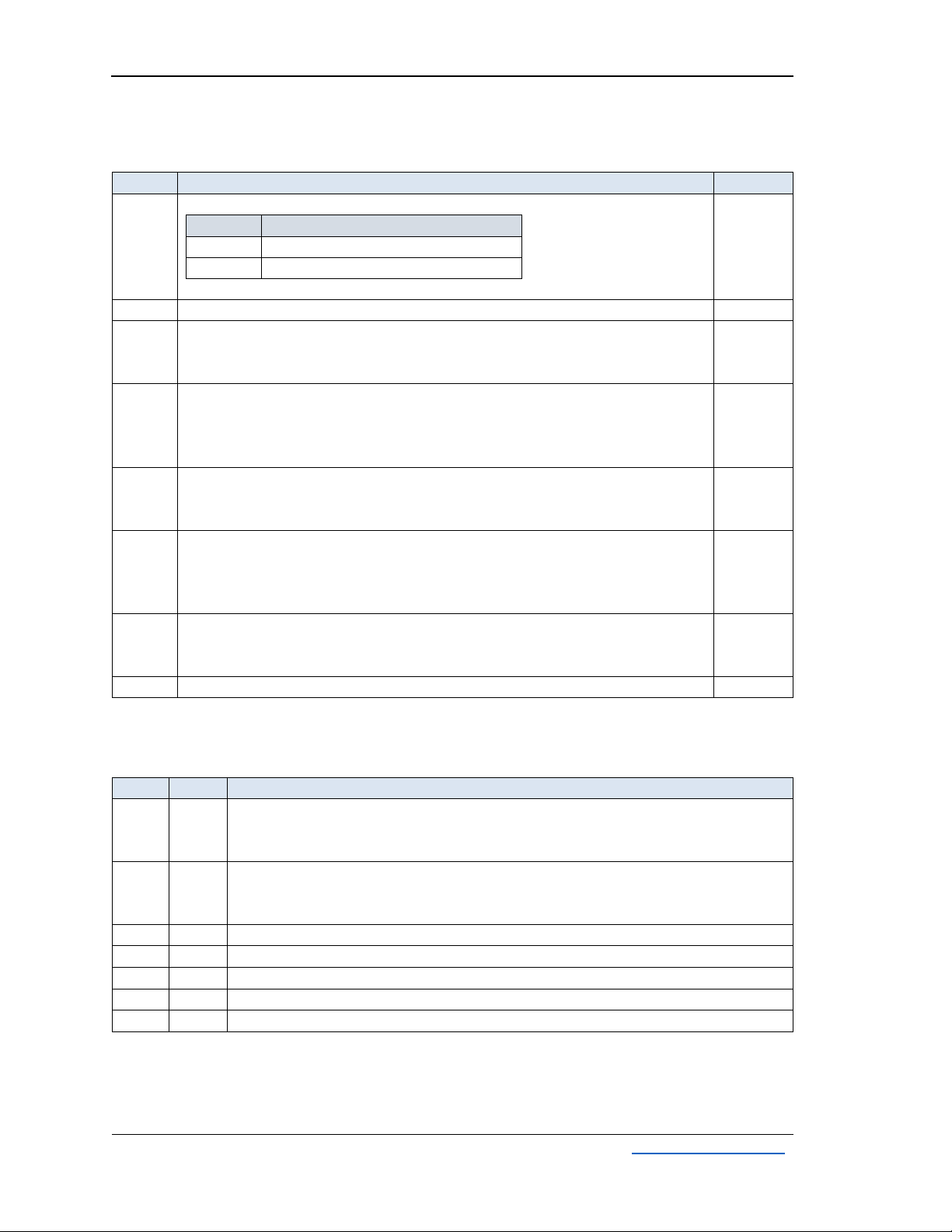
4.2 USB324 Power Control Modes
Table 4-1. USB324 Power Control Modes.
Mode
S1.1
Description
1
OFF
The USB324 is turned ON and OFF automatically when the computer is
turned ON and OFF
2
ON
The USB324 is always ON
Note: Disconnection of the fiber optic cable or cycling the USB324 power supply during operation
requires a computer restart.

AUS324 User’s Guide
Rev. 1.0
Adnacom Inc.
9 of 34
https://adnacom.com/
5System Installation
5.1 Installation Recommendations
ESD Warning: The electronic parts are sensitive to electrostatic discharges. Please
use an electrostatic wrist strap and/or conductive mat when executing the steps
below.
5.2 Preparing Your Computer
•The H14 and H18 cards do not support overclocking. Please make sure that the PCI Express
clock frequency is set to either the default value or 100 MHz in the BIOS.
•The optical transceivers used in the system do not support PCI Express link power
management. Therefore, disabling all power management features on the computer is
recommended. The step-by-step instructions for Windows 7, 8, and 10 can be found at
https://adnacom.com/aus324. For other OSs, please consult your OS documentation, and if
you need additional assistance, please contact the OS vendor.
5.3 Installing the H14 or H18 Host Adapter Card
•Power off the host computer and unplug its power cord.
•Remove the computer’s cover.
•Identify a PCIe slot on the motherboard that can accommodate x4 or x8 cards.
•Configure the H14 or H18 card using the DIP switch settings described in Table 7-2 or Table
8-2.
•Remove the metal bracket for the slot you have selected.
•Insert the H14 or H18 card into the identified PCIe slot by pushing on it gently. Secure the
card to the computer chassis using a screw.
•There should be sufficient airflow to keep the PCIe card temperature below the maximum
limit.
•Connect the power cord and verify that the red standby LED is ON when the computer is
OFF. If the standby LED is OFF, there is no +3.3Vaux voltage on the PCI slots. Check the BIOS
settings to enable the voltage or reset the BIOS settings to the default values. In Dell
computers, +3.3Vaux is enabled by selecting BIOS Settings->Power Management->Deep
Sleep Control->Disabled.
5.4 Installing the USB324 Unit
•Place the USB324 unit near the USB devices.
•Connect the power supply cable.
•Set the required power control mode described in section 4.2.
5.5 Installing QSFP Transceivers and Connecting Fiber Optic Cables
•Install QSFP transceivers or an AOC.
•If QSFP transceivers are used, connect the host adapter and USB324 with a fiber optic cable.
5.6 Turning on the System for the First Time
•Power on the computer and verify the installation, as indicated in section 6. All drivers are

AUS324 User’s Guide
Rev. 1.0
Adnacom Inc.
10 of 34
https://adnacom.com/
included in the Windows 10 and Linux operating systems. If the drivers are not installed
when the system is powered for the first time, the computer requires one or two restarts.
5.7 Connecting USB Devices
•Install software required to operate the USB devices.
•The USB devices can be connected or disconnected at any time as with any USB port.
•Check that the device is detected and installed correctly in the operating system.


AUS324 User’s Guide
Rev. 1.0
Adnacom Inc.
12 of 34
https://adnacom.com/
To see if your installation is successful, click on the arrow to the left of the ACPI to open it, then
within PCI Bus, check the lines containing the words “PCI Express Root” or “PCI standard PCI-to-
PCI bridge.” Under one of the lines, you should see three PCI-to-PCI bridges and two AsMedia USB
3.1 Host Controllers, as shown in Figure 6-2.
Figure 6-2. AUS324 System with H14 View in Device Manager.
AUS324 User’s Guide
Rev. 1.0
Adnacom Inc.
13 of 34
https://adnacom.com/
7H14 PCIe Host Adapter
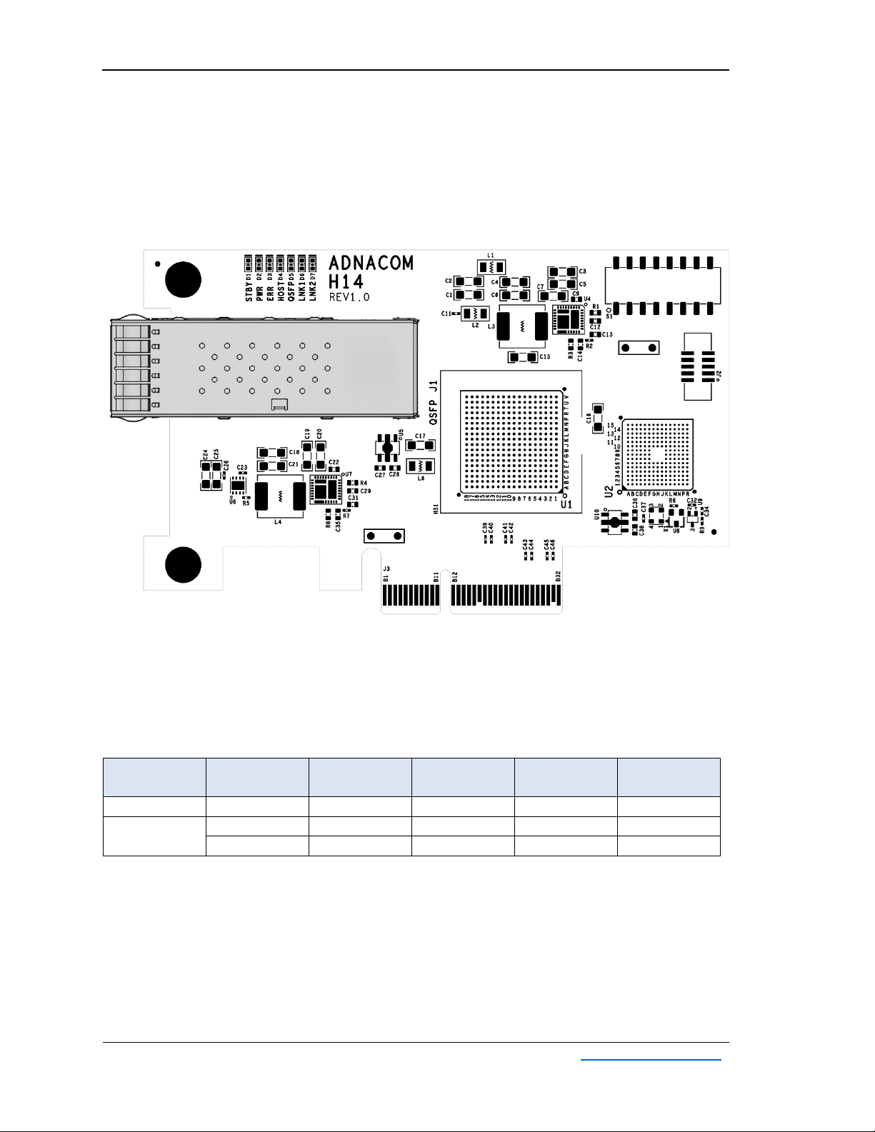
7.1 H14 Drawing
Figure 7-1. H14 Drawing.
7.2 H14 Cable Interface
Table 7-1. H14 PCIe Cable Interface.
Number of
PCIe Ports
Port
Number
Port Width
PCIe Lanes
QSFP
QSFP
TX/RX
1
1
x4
0–3
1
1–4
2
1
x2
0–1
1
1–2
2
x2
0–1
2
3–4
AUS324 User’s Guide
Rev. 1.0
Adnacom Inc.
14 of 34
https://adnacom.com/
7.3 H14 S1 DIP Switch Description
Table 7-2. H14 DIP Switch.
Switch
Description
Default
1
Cable Interface Configuration
S1.1
Configuration
OFF
1 port x4
ON
2 ports x2
Note: The USB324 works with the S1.1=ON configuration.
ON
2
Reserved
OFF
3
Gen 2 Cable Interface
OFF –Gen 3
ON –Gen 2. Set for Gen 2 ports or to limit the cable interface speed.
OFF
4
Optical Reset
OFF –Disabled
ON –Enabled. The lasers are turned OFF during the computer reset.
Note: Optical reset must be enabled for the USB324 adapter.
ON
5
Hot Plug Enable
OFF –Hot Plug is disabled
ON –Hot Plug is enabled
ON
6
Wake Enable
OFF –Wake is disabled
ON –Wake is enabled
Note: The wake signal is not used with the USB324 adapter.
OFF
7
H14 Configuration
OFF –Host adapter
ON –Remote adapter
OFF
8
Reserved
OFF
7.4 H14 LEDs Description
Table 7-3. H14 LEDs.
LED
Color
Description
D1
Red
Standby Status:
ON –Standby mode
OFF –The computer power supply is ON, or PCIe 3.3V AUX power is OFF.
D2
Green
Computer Power Status:
ON –The computer power supply is ON.
OFF –The computer power supply is OFF.
D3
Red
Error Status: Reserved
D4
Blue
Host Link Status: The status described in Table 7-4
D5
Green
QSFP 1 Status: The status described in Table 7-5
D6
Blue
Remote Link 1 Status: Port 1 link status described in Table 7-4
D7
Green
Remote Link 2 Status: Port 2 link status described in Table 7-4
AUS324 User’s Guide
Rev. 1.0
Adnacom Inc.
15 of 34
https://adnacom.com/
Table 7-4. PCIe Link Status.
PCIe Link LED
Description
OFF
Link is Down
Blinking, 0.5 sec ON, 0.5 sec OFF (1 Hz)
Link is Up, 2.5.0 GT/s
Blinking, 0.25 sec ON, 0.25 sec OFF (2 Hz)
Link is Up, 5.0 GT/s
ON
Link is Up, 8.0 GT/s
Table 7-5. QSFP Status.
QSFP LED
Description
OFF
QSFP is not powered
Blinking, 0.25 sec ON, 0.25 sec OFF (2 Hz)
Received optical power is below the worst-case
receiver sensitivity
ON
Transmitter and receiver are ON
AUS324 User’s Guide
Rev. 1.0
Adnacom Inc.
16 of 34
https://adnacom.com/
8H18 PCIe Host Adapter
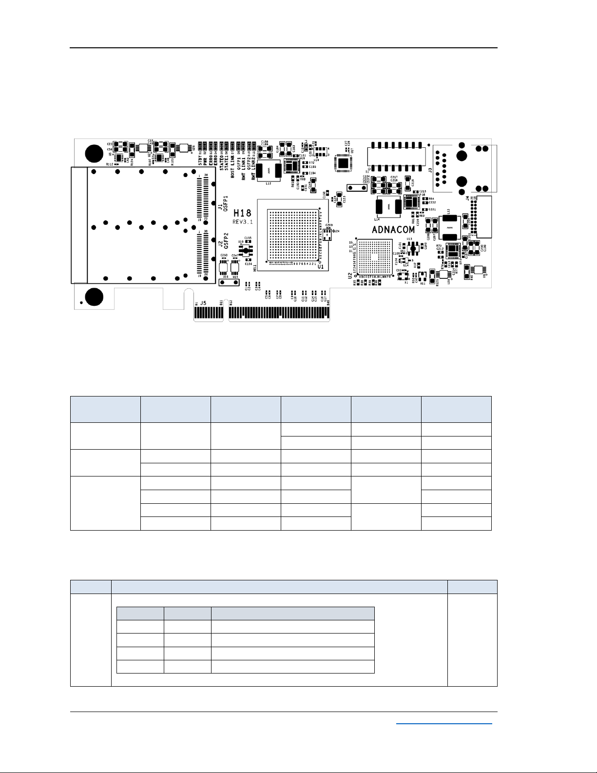
8.1 H18 Drawing
Figure 8-1. H18 Drawing.
8.2 H18 Cable Interface
Table 8-1. H18 PCIe Cable Interface.
Number of
PCIe Ports
Port
Number
Port Width
PCIe Lanes
QSFP
QSFP
TX/RX
1
1
x8
0-3
1
1-4
4-7
2
1-4
2
1
x4
0-3
1
1-4
2
x4
0-3
2
1-4
4
1
x2
0-1
1
1-2
2
x2
0-1
3-4
3
x2
0-1
2
1-2
4
x2
0-1
3-4
8.3 H18 S1 DIP Switch Description
Table 8-2. H18 DIP Switch.
Switch
Description
Default
1
2
Cable Interface Configuration
S1.1
S1.2
Configuration
OFF
OFF
1 port x8
ON
OFF
2 ports x4
OFF
ON
4 ports x2 (2 ports per QSFP)
ON
ON
Reserved
Note: The USB324 works with the S1.1=OFF, S1.2=ON configuration.
OFF
ON
AUS324 User’s Guide
Rev. 1.0
Adnacom Inc.
17 of 34
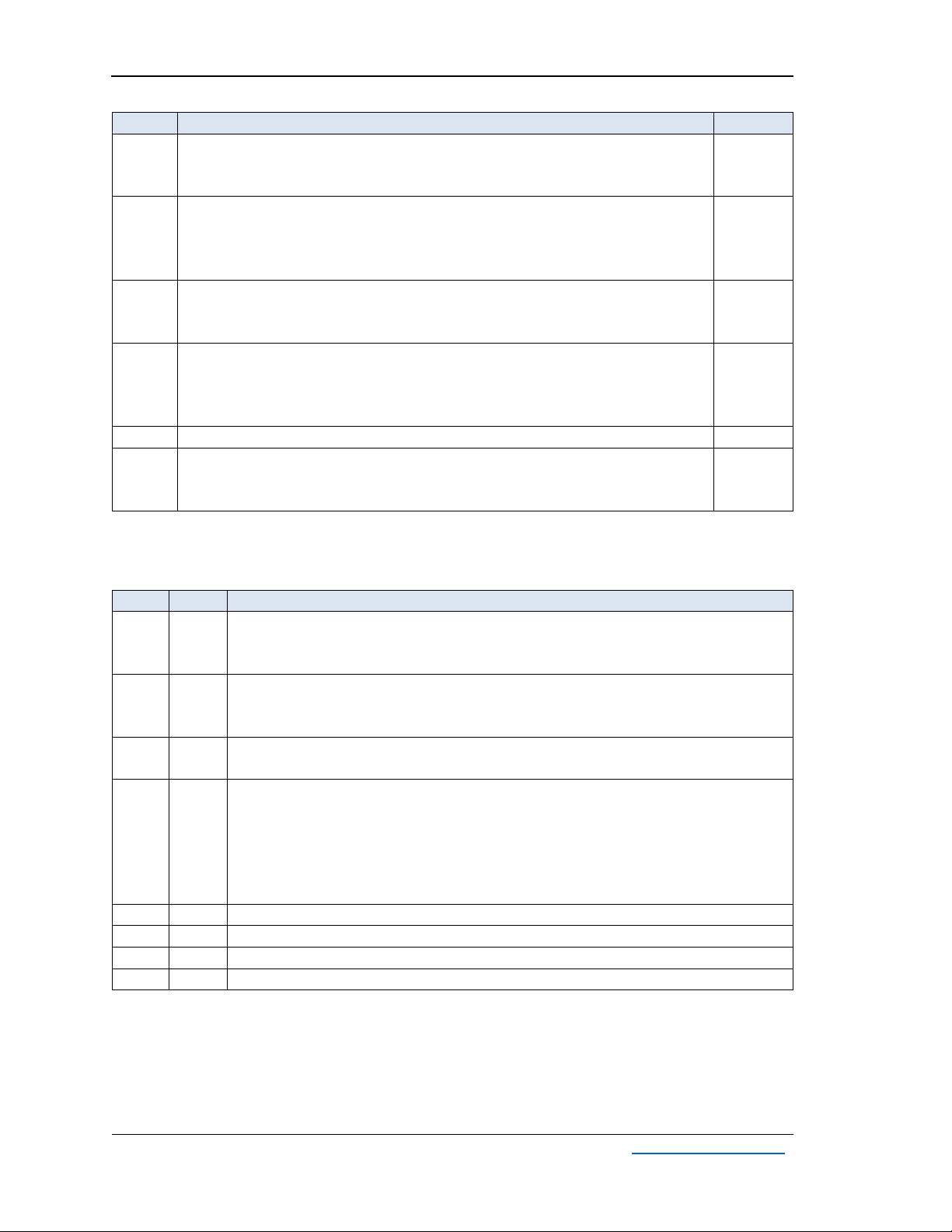
https://adnacom.com/
Switch
Description
Default
3
Gen 2 Cable Interface
OFF –Gen 3
ON –Gen 2. Set for Gen 2 ports or to limit the cable interface speed
OFF
4
Optical Reset
OFF –Disabled
ON –Enabled. The lasers are turned OFF during the computer reset.
Note: Optical reset must be enabled for the USB324 adapter.
ON
5
Hot Plug Enable
OFF –Hot Plug is disabled
ON –Hot Plug is enabled
ON
6
Wake Enable
OFF –Wake is disabled
ON –Wake is enabled
Note: The wake signal is not used with the USB324 adapter.
OFF
7
Reserved
OFF
8
IP Configuration
OFF –Static IP address 198.168.100.101
ON –User’s IP Configuration described in section 10.2
OFF
8.4 H18 LEDs Description
Table 8-3. H18 LEDs.
LED
Color
Description
D1
Red
Standby Status:
ON –standby mode
OFF –the computer power supply is ON, or PCIe 3.3V AUX power is OFF
D2
Green
Computer Power Status:
ON –the computer power supply is ON
OFF –the computer power supply is OFF
D3
D4
Red
Error Status: Reserved
D5
D6
Green
Status:
One and two ports configurations:
Reserved
Four ports configuration:
D5 –Port 2 link status described in Table 7-4
D6 –Port 4 link status described in Table 7-4
D7
Blue
Host Link Status: The status described in Table 7-4
D8
Green
QSFP 1 Status: The status described in Table 7-5
D9
Blue
Remote Link 1 Status: Port 1 link status described in Table 7-4
D10
Green
QSFP 2 Status: The status described in Table 7-5
AUS324 User’s Guide
Rev. 1.0
Adnacom Inc.
18 of 34
https://adnacom.com/
LED
Color
Description
D11
Blue
Remote Link 2 Status:
One port configuration:
The status is the same as the Remote Link 1 status if QSFP 2 is connected to the
remote device
Two ports configuration:
Port 2 link status described in Table 7-4
Four ports configuration:
Port 3 link status described in Table 7-4
8.5 H18 Connectors Description
Table 8-4. H18 Connectors.
Designator
Description
J1
QSFP 1 connector
J2
QSFP 2 connector
J3
Ethernet connector
J4
Test connector. Factory only.
AUS324 User’s Guide
Rev. 1.0
Adnacom Inc.
19 of 34
https://adnacom.com/
9USB324 Remote Unit
9.1 USB324 Drawings
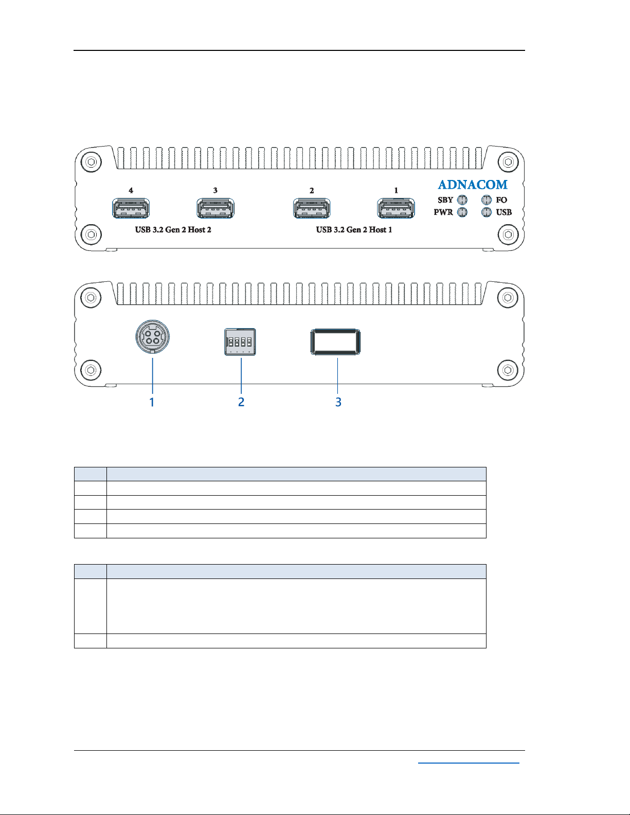
Figure 9-1. USB324 Front Panel.
Figure 9-2. USB324 Rear Panel.
9.2 USB324 Connectors
Table 9-1. USB324 Front Panel.
#
Description
1
Port 1 of USB Host Controller 1
2
Port 2 of USB Host Controller 1
3
Port 1 of USB Host Controller 2
4
Port 2 of USB Host Controller 2
Table 9-2. USB324 Rear Panel.
#
Description
1
Power: 5 V, 8 A
Mating connector: Kycon KPPX-4P or equivalent
Pins 1, 2: Ground
Pins 3, 4: +5 V
3
QSFP
AUS324 User’s Guide
Rev. 1.0
Adnacom Inc.
20 of 34
https://adnacom.com/
9.3 USB324 LEDs Description
Table 9-3. USB324 LEDs.
LED
Color
Description
SBY
Red
Standby Status:
ON –Standby mode
OFF –USB324 is ON, or the power supply is OFF.
PWR
Green
Power Status:
ON –USB324 is ON.
OFF –USB324 is OFF.
FO
Green
QSFP 1 Status: The status described in Table 7-5
USB
Green
USB Connectors Power Status:
ON –The power on all USB connectors is good.
Blinking N times with a 1-second pause –power failure.
N –The failed USB port number. The status is displayed sequentially for all
failed ports.
9.4 USB324 DIP Switch Description
Table 9-4. H18 DIP Switch.
Switch
Description
Default
1
USB324 Power Mode:
OFF –Automatic power ON and OFF controlled by the computer.
ON –Power is always ON.
OFF
2
Reserved
OFF
3
Reserved
OFF
4
Reserved
OFF
Table of contents


