ADOLF THIES CLIMA 4.3303.22 Series User manual

Instruction for use
020856/10/07
Wind Transmitter
- with analogue output
4.3303.22.xxx
THE WORLD OF WEATHER DATA - THE WORLD OF WEATHER DATA - THE WORLD OF WEATHER DATA
ADOLF THIES GmbH & Co. KG
Hauptstraße 76 37083 Göttingen Germany
Box 3536 + 3541 37025 Göttingen
Phone +49 551 79001-0 Fax +49 551 79001-65
www.thiesclima.com inf[email protected]

Safety Instructions
•Before operating with or at the device/product, read through the operating instructions.
This manual contains instructions which should be followed on mounting, start-up, and operation.
A non-observance might cause:
- failure of important functions
- endangerment of persons by electrical or mechanical effect
- damage to objects
•Mounting, electrical connection and wiring of the device/product must be carried out only by a qualified
technician who is familiar with and observes the engineering regulations, provisions and standards applicable in
each case.
•Repairs and maintenance may only be carried out by trained staff or Adolf Thies GmbH & Co. KG. Only
components and spare parts supplied and/or recommended by Adolf Thies GmbH & Co. KG should be used
for repairs.
•Electrical devices/products must be mounted and wired only in a voltage-free state.
•Adolf Thies GmbH & Co KG guarantees proper functioning of the device/products provided that no
modifications have been made to the mechanics, electronics or software, and that the following points are
observed:
•All information, warnings and instructions for use included in these operating instructions must be taken into
account and observed as this is essential to ensure trouble-free operation and a safe condition of the measuring
system / device / product.
•The device / product is designed for a specific application as described in these operating instructions.
•The device / product should be operated with the accessories and consumables supplied and/or recommended
by Adolf Thies GmbH & Co KG .
•Recommendation: As it is possible that each measuring system / device / product may,under certain conditions,
and in rare cases, may also output erroneous measuring values, it is recommended using redundant systems
with plausibility checks for security-relevant applications.
Environment
•As a longstanding manufacturer of sensors Adolf Thies GmbH & Co KG is committed to the
objectives of environmental protection and is therefore willing to take back all supplied
products governed by the provisions of "ElektroG" (German Electrical and Electronic
Equipment Act) and to perform environmentally compatible disposal and recycling. We are
prepared to take back all Thies products concerned free of charge if returned to Thies by our
customers carriage-paid.
•Make sure you retain packaging for storage or transport of products. Should packaging
however no longer be required, please arrange for recycling as the packaging materials are
designed to be recycled.
Documentation
•© Copyright Adolf Thies GmbH & Co KG, Göttingen / Germany
•Although these operating instruction has been drawn up with due care, Adolf Thies GmbH & Co KG can
accept no liability whatsoever for any technical and typographical errors or omissions in this document that
might remain.
•We can accept no liability whatsoever for any losses arising from the information contained in this document.
•Subject to modification in terms of content.
•The device / product should not be passed on without the/these operating instructions.
2 - 12 020856/10/07

Contents
1Models......................................................................................................................................3
2Application................................................................................................................................4
3Set-up of the instrument............................................................................................................ 4
4Recommendation Site Selection / Standard Installation............................................................ 4
5Installation................................................................................................................................. 5
5.1 Mounting of the cup star.....................................................................................................5
5.2 Electrical Mounting ............................................................................................................. 6
5.3 Mounting of the Wind Transmitter....................................................................................... 7
6Maintenance .............................................................................................................................7
7Connecting Diagram ................................................................................................................. 7
8Technical Data..........................................................................................................................9
9Dimension diagram...................................................................................................................9
10 EC-Declaration of Conformity.............................................................................................. 10
1 Models
Order - no.
Measuring range
Electrical output
Model
4.3303.22.040
0...50 m/s
0...20 mA (Load resistor: ≤ 500 Ω)
Standard
4.3303.22.041 0...50 m/s
4...20 mA (Load resistor: ≤ 500 Ω)
Standard
4.3303.22.060 0...50 m/s
0….1 V (Load resistor: ≥ 1000 Ω)
Standard
4.3303.22.061 0...50 m/s
0...10 V
(Load resistor: ≥ 1000 Ω)
Standard
4.3303.22.073
0...50 m/s
0.… 5 V (Load resistor: ≥ 1000 Ω)
Standard
4.3303.22.640
0…60 m/s
0...20 mA (Load resistor: ≤ 500 Ω)
Standard
4.3303.22.641
0…60 m/s
4...20 mA (Load resistor: ≤ 500 Ω)
Standard
4.3303.22.660
0…60 m/s
0… 1 V (Load resistor: ≥ 1000 Ω)
Standard
4.3303.22.661
0…60 m/s
0...10 V
(Load resistor: ≥ 1000 Ω)
Standard
4.3303.22.673
0…60 m/s
0.… 5 V (Load resistor: ≥ 1000 Ω)
Standard
4.3303.22.841
0…60 m/s
4...20 mA (Load resistor: ≤ 500 Ω)
“Ship version” *
- reinforced cup star
- special ball bearing
*Wind transmitters for heavy mechanical load, for ex. on ships, wind power plants or the like.
3 - 12 020856/10/07

2 Application
The wind transmitter is used for the registration of the horizontal component of the wind velocity.
The measuring value will be placed at the output as analogue signal. The signal can be given to
display instruments, recording instruments, datalogger as well as process wise systems. The wind
transmitter is equipped with an electronically regulated heating system in order to prevent ice and
frost from the ball bearings and the outer rotation parts.
Power supply unit, Order no. 9.3388.00.000 provides the transmitter and the heating system with
current. It is advisable to attach Lightning rod, Order no. 4.3100.99.000 in areas with considerable
lightning activity.
3 Set-up of the instrument
A low-inertia light metallic cup star is set into rotation by the wind. Through the opto-electronic
rotating frequency-scanning the resulting pulse frequency is converted through an integrated
measuring transducer into an analogue signal. The measuring transducer is normally provided with
voltage from the heating system. The instrument can also be used without the heating system. In
this case the measuring transducer has to be provided with a separate voltage supply. Input and
outputs have to be protected from overload by Transzorb diodes.
The outer parts of the instrument are made of corrosion-resistant anodised aluminium. The
sensitive parts inside of the instrument are protected from precipitation through labyrinth seals and
o-rings. The instrument is designed to be mounted to a mast, the electrical connection is located in
the stem of the transmitter.
It consists of the following parts: 1 Case
1 Cup star
1 Connection plug
4 Recommendation Site Selection / Standard Installation
According to international regulations, the surface wind should be measured at a height of 10 m
above flat, open terrain, in order to achieve comparable values. An open terrain is defined as
terrain where the distance between the wind-measuring instrument and the next obstacle is at least
ten times the height of this obstacle (see VDI 3786, Part 2). If the regulation cannot be adhered to,
the measuring instrument should be installed at a height at which the measurement values are not
influenced by any local obstacles. In any case, the measuring instruments are to be installed at a
height of 6 to 10 m above the mean height of the buildings or trees in the vicinity. If it is necessary
to install the instrument on a roof, it should be installed in the centre of the roof in order to avoid
any preferential directions.
4 - 12 020856/10/07

5 Installation
Attention:
Storing, mounting and operation under weather conditions is
permissible only in vertical position, as otherwise water can get into
the instrument.
Remark:
When using fastening adapters (angle, traverses, etc.) please take a possible
effect by turbulences into consideration.
5.1 Mounting of the cup star
Unscrew the cap nut (SW 8) from the wind velocity sensor case and remove the disk. Keep the
rubber sealing washer in the protection cap. Set the cup star into position in such a way that the
dowel pin in the cup star catches in the nut of the protective cap. Replace the disk and re-screw the
cap nut. Hold the transmitter on the protective cap not on the cup.
5 - 12 020856/10/07

5.2 Electrical Mounting
A shielded cable with a diameter of 5..8 mm and a core section of 0,5…0,75 mm² must be soldered
on to the enclosed plug.
•The number of required cores, and the PIN assignment is stated in the connection diagram
(chapter 7).
Cable recommendation
Type/ No. of cores /Diameter
Cable diameter
LIYCY 3 x 0,5 mm²
LIYCY 5 x 0,5 mm²
ca. 5 mm
ca. 7 mm
Coupling socket 201041 (5-pol), Type Binder, Series 691
1. Removing Coupling socket
2. Stringing coupling socket on cable
3. Stripping cable sheath 20 mm
4. Putting uncovered shield backwards onto the cable sheath
5. Stripping uncovered cable cores 5 mm
6. Pushing shrink hose over cable cores
7. Soldering stripped cable cores onto the solder filament of the bush insert,
pushing shrink hose over the soldering afterwards, and shrinking it.
8. Fastening cable and shield in the carrier sleeve by means of the clamp.
9. Mount coupling socket
6 - 12 020856/10/07

5.3 Mounting of the Wind Transmitter
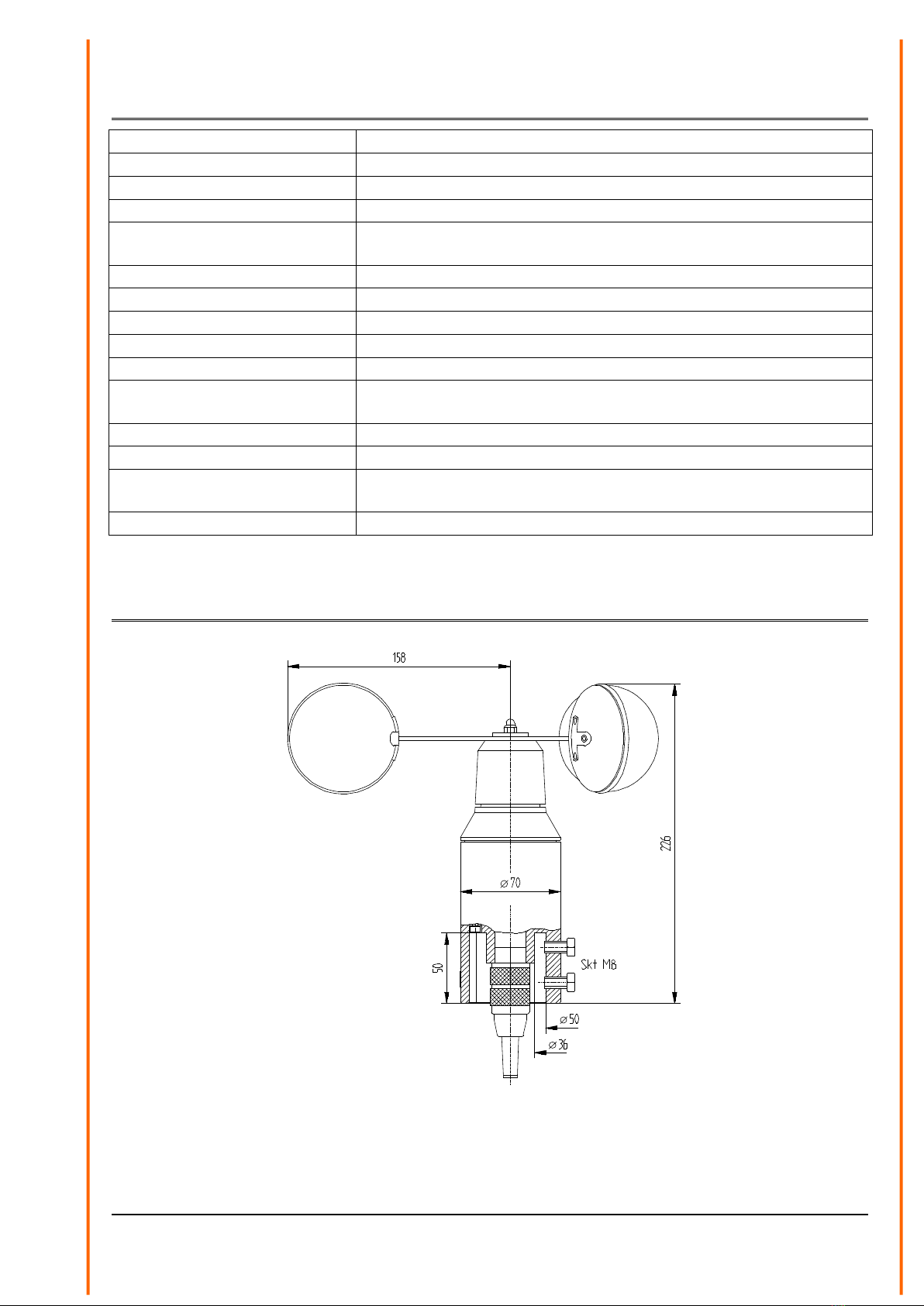
Mount the transmitter to a short piece of pipe of R 1½“ (Ø 48 mm) and a length of 50 mm. The
short piece of pipe must have an internal diameter of at least 36 mm as the wind transmitter must
be connected electrically with a plug from below. Once the electrical connection has been carried
out, set the wind transmitter onto the short piece and fasten it to the shaft with the two hexagonal
screws.
6 Maintenance
After proper mounting the instrument works maintenance free.
Heavy pollution can clog up the slit between the rotating and the stationary parts of the wind
transmitter. This slit must be kept clean.
Remark:
Please use only original packing for transporting the instrument.
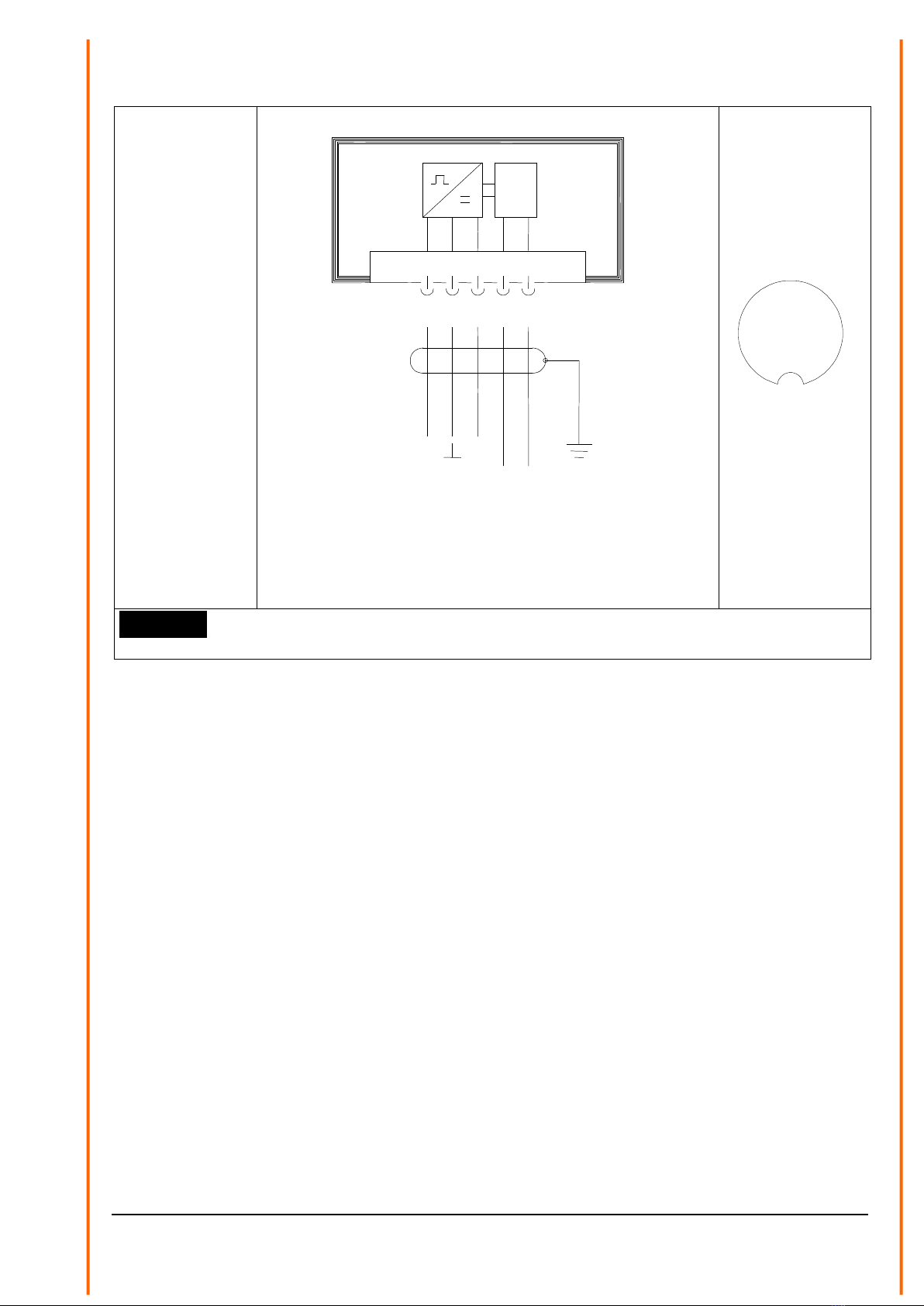
7 Connecting Diagram
Order - no.
4.3303.22.040
4.3303.22.041
4.3303.22.060
4.3303.22.061
4.3303.22.073
4.3303.22.640
4.3303.22.641
4.3303.22.660
4.3303.22.661
4.3303.22.673
4.3303.22.841
Wind Transmitter: Operation with Heating
5 pol. Binder Steckverb. / Plug
12345
Heizung
Heating
20 W
Schirm
Shield
Ausgang / Output
Erde / Earth
+
nicht belegt
not connected
NC
Versorgung / Power
24 V AC / DC 20 W
+
~ ~
View on the
soldered side of
the coupling
socket
1
2
3
4
5
Attention:
The power ground must be galvanically isolated from the signal ground
7 - 12 020856/10/07
Order - no.
4.3303.22.040
4.3303.22.041
4.3303.22.060
4.3303.22.061
4.3303.22.073
4.3303.22.640
4.3303.22.641
4.3303.22.660
4.3303.22.661
4.3303.22.673
4.3303.22.841
Wind Transmitter: Operation without Heating
5 pol. Binder Steckverb. /Plug
1
2
3
4
5
Erde / Earth
Heizung
Heating
20 W
Schirm
Shield
Ausgang / Output
Versorgung / Power
15... 24 V DC
nicht belegt
not connected
NC
NC
+
+
View on the
soldered side of
the coupling
socket
1
2
3
4
5
Attention:
NC: Cable isolating – no connecting
8 - 12 020856/10/07
8 Technical Data
Measuring range
see models available
Starting speed
0,3 m/s
Max. load
60 m/s
Electrical output
see models available
Accuracy
± 0,4 m/s resp. 2,5 %
of meas. value
Resolution
0,05 m wind run
Wind load at 35 m/s
approx. 10N
Distance constant
5 m
Ambient temperature
-35...+80°C
Operating voltage
With Heating
24 V AC/DC ca. 20 W;
electronically controlled
Without Heating
15 ... 24 V DC
Connecting
5-pole plug
Mounting
onto mast tube
1 ½" , DIN 2441
Weight
1 kg
9 Dimension diagram
Figure 1: Dimension diagram
9 - 12 020856/10/07

10 EC-Declaration of Conformity
Document-No.: 000434 Month: 06 Year: 08
Manufacturer: A D O L F T H I E S G m b H & C o. K G
Hauptstr. 76
D-37083 Göttingen
Tel.: (0551) 79001-0
Fax: (0551) 79001-65
email: Info@ThiesClima.com
Description of Product: Wind Transmitter, Wind Direction Transmitter, Combined Wind Transmitter
Article No.
4.3125.32.040
4.3125.32.041
4.3125.32.060
4.3125.32.061
4.3125.32.073
4.3125.32.841
4.3303.22.040
4.3303.22.041
4.3303.22.060
4.3303.22.061
4.3303.22.073
4.3303.22.640
4.3303.22.641
4.3303.22.660
4.3303.22.661
4.3303.22.673
4.3303.22.841
4.3324.31.040
4.3324.31.041
4.3324.31.061
4.3324.31.073
4.3324.31.640
4.3324.31.641
4.3324.31.661
4.3324.31.673
4.3324.31.941
specified technical data in the documen
020853/10/07; 020854/11/07; 020848/10/07
The indicated products correspond to the essential requirement of the following European Directives and Regulations:
2004/108/EC DIRECTIVE 2004/108/EC OF THE EUROPEAN PARLIAMENT AND OF THE COUNCIL
of 15 December 2004 on the approximation of the laws of the Member States relating to
electromagnetic compatibility and repealing Directive 89/336/EEC
2006/95/EC DIRECTIVE 2006/95/EC OF THE EUROPEAN PARLIAMENT AND OF THE COUNCIL
of 12 December 2006 on the harmonisation of the laws of Member States relating to electrical
equipment designed for use within certain voltage limits
552/2004/EC Regulation (EC) No 552/2004 of the European Parliament and the Council of 10 March 2004
on the interoperability of the European Air Traffic Management network
(the interoperability Regulation)
The indicated products comply with the regulations of the directives. This is proved by the compliance with the following
standards:
Reference number
Specification
IEC 61000-6-2: 2005
Electromagnetic compatibility
Immunity for industrial environment
IEC 61000-6-3: 2006
Electromagnetic compatibility
Emission standard for residential, commercial and light industrial environments
IEC 61010-1: 2001
Safety requirements for electrical equipment for measurement, control and
laboratory use. Part 1: General requirements
Place: Göttingen Date: 30.06.2008
This declaration certificates the compliance with the mentioned directives, however does not include any warranty of characteristics.
Please pay attention to the security advises of the provided instructions for use.
10 - 12 020856/10/07

11 - 12 020856/10/07

ADOLF THIES GmbH & Co. KG
Hauptstraße 76 37083 Göttingen Germany
P.O. Box 3536 + 3541 37025 Göttingen
Phone +49 551 79001-0 Fax +49 551 79001-65
- Alterations reserved -
12 - 12 020856/10/07
This manual suits for next models
11
Table of contents
Other ADOLF THIES Transmitter manuals

Popular Transmitter manuals by other brands


Community Controls
Community Controls Monarch 295SEPA2KC manual

Invisible systems
Invisible systems QC0150 installation manual

Microsensor
Microsensor MDM6000 Series Operation manual

ELT Sensor
ELT Sensor CD-300 Operation manual

SkyLink
SkyLink TB-318 user manual

Air Monitor
Air Monitor MASS-tron II/CEM Installation, operation and maintenance manual