ADOLF THIES CLIMA 4.3324.32.000 User manual

THE WORLD OF WEATHER DATA - THE WORLD OF WEATHER DATA - THE WORLD OF WEATHER DATA
Instruction for Use
021591/02/09
Combined Wind Transmitter
Output: 8 Bit parallel
4.3324.32.000 / 001
ADOLF THIES GmbH & Co. KG
Hauptstraße 76 37083 Göttingen Germany
Box 3536 + 3541 37025 Göttingen
Phone +49 551 79001-0 Fax +49 551 79001-65

Safety Instructions
• Before operating with or at the device/product, read through the operating instructions.
This manual contains instructions which should be followed on mounting, start-up, and operation.
A non-observance might cause:
- failure of important functions
- Endangering of persons by electrical or mechanical effect
- Damage to objects
• Mounting, electrical connection and wiring of the device/product must be carried out only by a qualified technician
who is familiar with and observes the engineering regulations, provisions and standards applicable in each case.
• Repairs and maintenance may only be carried out by trained staff or Adolf Thies GmbH & Co. KG. Only
components and spare parts supplied and/or recommended by Adolf Thies GmbH & Co. KG should be used for
repairs.
• Electrical devices/products must be mounted and wired only in voltage-free state.
• Adolf Thies GmbH & Co KG guarantees proper functioning of the device/products provided that no
modifications have been made to the mechanics, electronics or software, and that the following points are
observed:
• All information, warnings and instructions for use included in these operating instructions must be taken into
account and observed as this is essential to ensure trouble-free operation and a safe condition of the measuring
system / device / product.
• The device / product is designed for a specific application as described in these operating instructions.
• The device / product should be operated with the accessories and consumables supplied and/or recommended
by Adolf Thies GmbH & Co KG .
• Recommendation: As it is possible that each measuring system / device / product under certain conditions, and
in rare cases, may also output erroneous measuring values, it is recommended using redundant systems with
plausibility checks with security-relevant applications.
Environment
• As a longstanding manufacturer of sensors Adolf Thies GmbH & Co KG is committed to the
objectives of environmental protection and is therefore willing to take back all supplied products
governed by the provisions of "ElektroG" (German Electrical and Electronic Equipment Act)
and to perform environmentally compatible disposal and recycling. We are prepared to take
back all Thies products concerned free of charge if returned to Thies by our customers
carriage-paid.
• Make sure you retain packaging for storage or transport of products. Should packaging
however no longer be required, arrange for recycling as the packaging materials are designed
to be recycled.
Documentation
• © Copyright Adolf Thies GmbH & Co KG, Göttingen / Germany
• Although this operating instruction has been drawn up with due care, Adolf Thies GmbH & Co KG can accept
no liability whatsoever for any technical and typographical errors or omissions in this document that might
remain.
• We can accept no liability whatsoever for any losses arising from the information contained in this document.
• Subject to modification in terms of content.
• The device / product should not be passed on without the/these operating instructions.
2 - 14 021591/02/09

3 - 14 021591/02/09
Contents
1Models available ........................................................................................................................ 4
2Application ................................................................................................................................. 4
3Construction and Mode of Operation ......................................................................................... 4
4Recommendation Side Selection/ Standard Installation ............................................................ 5
5Installation.................................................................................................................................. 6
5.1 Mounting of wind vane ........................................................................................................ 6
5.2 Mounting of Cup Star .......................................................................................................... 7
5.3 Mounting of Wind Transmitter ............................................................................................. 7
5.4 Electrical Mounting .............................................................................................................. 8
6Maintenance .............................................................................................................................. 8
7Connecting Diagrams ................................................................................................................ 8
8Technical Data........................................................................................................................... 9
9Dimensional Drawings ............................................................................................................. 10
10 EC-Declaration of Conformity............................................................................................... 12
Figures
Figure 1: Thies Code table for 8 bit parallel ..................................................................................... 5
Figure 2: Dimension 4.3324.32.000 ............................................................................................... 10
Figure 3: Dimension 4.3324.32.001 ............................................................................................... 11

4 - 14 021591/02/09
1 Models available
Order-No. Measuring range Electrical Output Model
4.3324.32.000 WV 0,3 ... 50 m/s
WD 0 ... 360°
3 … 1042 Hz (with Offset)
8 Bit parallel (with Offset) Standard version
4.3324.32.001 WV 0,3 ... 50 m/s
WD 0 … 360°
3 … 1042 Hz (with Offset)
8 Bit parallel (with Offset)
Ship version*
(short wind vane,
reinforced cup star, special
ball bearing)
* Comb. Wind transmitters for heavy mechanical load, for ex. on ships, wind power plants or the like.
The combined wind transmitters are shipped in semi-mounted state, in order to avoid transport
damages and to keep the package small.
The following parts are included in delivery: 1 x combined wind transmitter, pre-mounted
1 x cup star
1 x wind vane
1 x connecting plug
1 x Instruction
2 Application
The combined wind transmitter serves for the acquisition of the horizontal components of the wind
speed and the wind direction. All measuring values are available at the outputs analogue signals.
They can be output to THIES-display instruments, and systems or for further processing.
For winter operation the instruments are equipped with an electronically regulated heating in order
to guarantee a smooth running of the ball bearings, and to avoid ice-formation at the slot of the
outer rotation parts. The electrical supply of wind transmitter heating is carried out, for ex., by our
power supply unit, order-no. 9.3388.00.000.
3 Construction and Mode of Operation
The housing, cup star and wind vane are made of aluminum, die the surfaces are anodized. The
bow consists of stainless steel. Labyrinth seals and o-rings protect the sensitive internal parts from
precipitation. The instrument is designed for mounting to a mast tube; the electrical plug connection
is situated in the transmitter shaft.
A low-inertia light-metal cup star (in ball bearings) is set into rotation by the wind. A pulse frequency
is available at the output through the opto-electronic revolution-scanning.
The wind direction is acquired by means of an inertia-free wind vane. The axis of the wind vane is
running in ball bearings and carries a diametrically magnetized magnet at the inner end. The angle
position of the axis is scanned contact-free by a TMR- Sensor (Tunnel Magneto Resistance)
through the position of the magnet field. As signal this sensor outputs two cosine- and sinus-
depending voltages.

5 - 14 021591/02/09
A connected micro-controller calculates from these voltages the wind direction in 144 sectors (2.5° /
sector). Related to sector 1 is the wind direction 0° – 2,5°, sector 144 corresponds to the wind
direction 357.5°- 360°.
Sector
Gray-Code
Angle degree
Sector
Gray-Code
Angle degree
Sector
Gray-Code
Angle degree
Sector
Gray-Code
Angle degree
Sector
Gray-Code
Angle degree
Sector
Gray-Code
Angle degree
1 0 0,0 25 20 60,0 49 40 120,0 73 228 180,0 97 184 240,0 121 156 300,0
2 1 2,5 26 21 62,5 50 41 122,5 74 229 182,5 98 185 242,5 122 157 302,5
3 3 5,0 27 23 65,0 51 43 125,0 75 231 185,0 99 187 245,0 123 159 305,0
4 2 7,5 28 22 67,5 52 42 127,5 76 230 187,5 100 186 247,5 124 158 307,5
5 6 10,0 29 18 70,0 53 46 130,0 77 226 190,0 101 190 250,0 125 154 310,0
6 7 12,5 30 19 72,5 54 47 132,5 78 227 192,5 102 191 252,5 126 155 312,5
7 5 15,0 31 17 75,0 55 45 135,0 79 225 195,0 103 189 255,0 127 153 315,0
8 4 17,5 32 16 77,5 56 44 137,5 80 224 197,5 104 188 257,5 128 152 317,5
9 12 20,0 33 48 80,0 57 36 140,0 81 160 200,0 105 180 260,0 129 136 320,0
10 13 22,5 34 49 82,5 58 37 142,5 82 161 202,5 106 181 262,5 130 137 322,5
11 15 25,0 35 51 85,0 59 39 145,0 83 163 205,0 107 183 265,0 131 139 325,0
12 14 27,5 36 50 87,5 60 38 147,5 84 162 207,5 108 182 267,5 132 138 327,5
13 10 30,0 37 54 90,0 61 34 150,0 85 166 210,0 109 178 270,0 133 142 330,0
14 11 32,5 38 55 92,5 62 35 152,5 86 167 212,5 110 179 272,5 134 143 332,5
15 9 35,0 39 53 95,0 63 33 155,0 87 165 215,0 111 177 275,0 135 141 335,0
16 8 37,5 40 52 97,5 64 32 157,5 88 164 217,5 112 176 277,5 136 140 337,5
17 24 40,0 41 60 100,0 65 96 160,0 89 172 220,0 113 144 280,0 137 132 340,0
18 25 42,5 42 61 102,5 66 97 162,5 90 173 222,5 114 145 282,5 138 133 342,5
19 27 45,0 43 63 105,0 67 99 165,0 91 175 225,0 115 147 285,0 139 135 345,0
20 26 47,5 44 62 107,5 68 98 167,5 92 174 227,5 116 146 287,5 140 134 347,5
21 30 50,0 45 58 110,0 69 102 170,0 93 170 230,0 117 150 290,0 141 130 350,0
22 31 52,5 46 59 112,5 70 103 172,5 94 171 232,5 118 151 292,5 142 131 352,5
23 29 55,0 47 57 115,0 71 101 175,0 95 169 235,0 119 149 295,0 143 129 355,0
24 28 57,5 48 56 117,5 72 100 177,5 96 168 237,5 120 148 297,5 144 128 357,5
Figure 1: Thies Code table for 8 bit parallel
4 Recommendation Side Selection/ Standard Installation
In general wind measurement instruments should be able to detect the wind conditions of a large
area. In order to obtain comparable values when determining the surface wind, measurements
should be taken at a height of 10 meters over an even unobstructed area. An unobstructed area
means that the distance between the wind transmitter and an obstacle should be at least 10 times
the height of the obstacle (s. VDI 3786). If it is not possible to fulfil this condition, then the wind
transmitter should be set up a height where local obstacles do not influence the measured values to
any significant extent (approx. 6 - 10 m above the obstacle).
The wind transmitter should be set up in the centre of flat roofs and not on the roof side in order to
avoid bias in the direction (privileged directions).

5 Installation
Attention:
Storing, mounting and operation under weather conditions is
permissible only in vertical position, as otherwise water can get
into the instrument.
Remark:
When using fastening adapters (angle, traverses, hangers etc.) please take a
possible effect by turbulences into consideration.
Remark:
It is advisable to attach lightning rod, order no. 4.3100.99.000 in areas with
considerable lightning activity.
5.1 Mounting of wind vane
Tools
• Screw wrench SW 8
Mounting of wind vane
1. Remove wind transmitter
housing and wind vane from the
packing.
2. Screw off cap nut (SW 8) The
gasket remains in the protective
cap
2. Mounting of wind vane acc. to
figure. The dowel at the wind
vane must catch the notch of the
protective cap. The cap nut is to
be screwed tightly.
6 - 14 021591/02/09

5.2 Mounting of Cup Star
Tools
• Screw wrench SW 8
Mounting
1. Remove cup star from the
packing.
2. Screw-off cap nut (SW 8) and
remove disc..
The gasket remains in the
protective cap.
1. Mounting of cup star acc. to
figure.
The dowel at the cup star cross
must catch the notch of the
protective cap. The cap nut is to
be screwed tightly.
5.3 Mounting of Wind Transmitter
The transmitter can be mounted onto a tube of R 11/2" ( ¬48,3 mm), 50 mm long. The internal
diameter of the mounting tube must be at least 40 mm since the transmitter will be plugged into an
electrical system from below. Solder a cable (for ex. LiYCY) with the required number of leads of
each 0,5 mm2onto the enclosed plug. After electrical connection, set the wind transmitter onto the
tube. North marking and bow shall indicate to the North.
North Alignment
Rotate the case markings (north marking) on the shaft and on the protective cap until they are
aligned. Then select an obvious point in a northerly direction in the surroundings (a tree, a building
etc.) with the aid of a compass. Take a bearing on this point over the wind vane and the counter
weight of the wind direction transmitter, and when these coincide screw the wind transmitter into
place. (the north marking must indicate to the geographic north).
The instrument is fixed on the shaft by means of the two hexagon head screws.
Alignment of the comb. Wind Transmitter on a Ship
• The reference point for the wind transmitter is the roll-axis of the ship, whereat “0°” is related
to the ship bow.
Rotate the case markings (north marking) on the shaft and on the protective cap until they are
aligned. Take a bearing on ship bow over the wind vane and the counter weight of the wind
direction transmitter, and when these coincide screw the wind transmitter into place. (the north
marking must indicate to the geographic north).
• When aligning the comb. wind transmitter on other mobile objects (for ex. vehicles, wind
power plants etc.) this procedure can be adopted
7 - 14 021591/02/09
5.4 Electrical Mounting
For electrical connection please refer to the connecting diagram.
6 Maintenance
After proper mounting the instrument works maintenance free.
Heavy pollution can clog up the slit between the rotating and the stationary parts of the wind
transmitter. This slit must be kept clean.
Remark:
Please use only original packing for transporting the instrument.
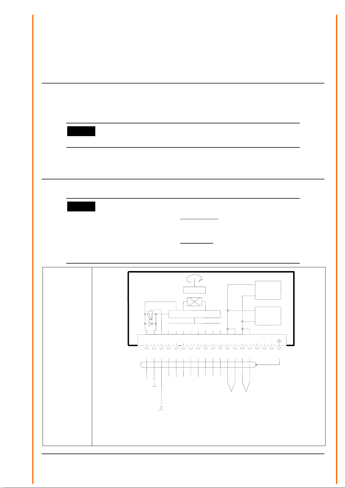
7 Connecting Diagrams
Remark:
- The cable shield should be connected on both sides (to the plug of
the wind transmitter and to the data logging) in case the data logging
or the like is on the same electrical potential.
- The cable shield should be connected on one side (only to the data
logging) in case there are potential differences between wind
transmitter and data logging.
Order-No.
4.3324.32.000
4.3324.32.001
WG / WV WR / WD Heatin
g
W
Heatin
g
W
Power DC Wind Direction
Wind Velocity
12345678910111213141516171819
19 pol. Euchner Steckverbindung / Plug
+3,3 ... 28V 8 - bit - Gray - Code
Windrichtung Versorgung Heizung
Power Heating
24V AC / DC 40W
Windgeschwindigkeit
Versorgung DC
Schirm
B C EDA F G H
Hz
3 ... 1042 Hz
= 0,3 ... 50 m/s
Hz
Heizun
g
W
20
Heizun
g
W
20 W
B C ED
A
F G H
N
S
C P U
8 - 14 021591/02/09

9 - 14 021591/02/09
8 Technical Data
Wind Speed Wind Direction
Measuring range 0,3 ... 50 m/s 0 ... 360°
Start-up (with 4.3324.32.000) 0,3 m/s <0,6 m/s at 90° vane move
Start-up (with 4.3324.32.001) 0,3 m/s <1 m/s at 90° vane move
Accuracy ±0,3 m/s resp.
2 % of meas. value
±1,5°
Resolution 0,05 m wind run 2,5°
Distance constant 5 m --------------------------------------
Damping ratio
(acc. to ASTM D 5366-96)
with 4.3324.32.000
--------------------------------------- D > 0,3
Electr. output 3 ... 1042 Hz 8 bit parallel (Code)
Voltage supply (UB) 3,3...28 V DC 3,3...28 V DC
Output signal, unloaded ULow ≈1 V / UHeight ≈UBULow ≈0.7V / UHeight ≈UB
Output signal, loaded < 5 mA < 10 mA
Current consumption
(unloaded)
< 2.5 mA (UB= 15 V) < 2 mA (UB= 15 V)
Max. wind load 60 m/s
Heating 24 V DC/AC, approx. 40 W, electronically regulated
Ambient temperature -35...+80°C
Protection IP 55
Wind load at 35 m/s approx. 50 N
Mounting onto mast tube 1 ½“, for ex. DIN 2441
Connection 19-pole plug connection in the shaft
Weight 2,8 kg
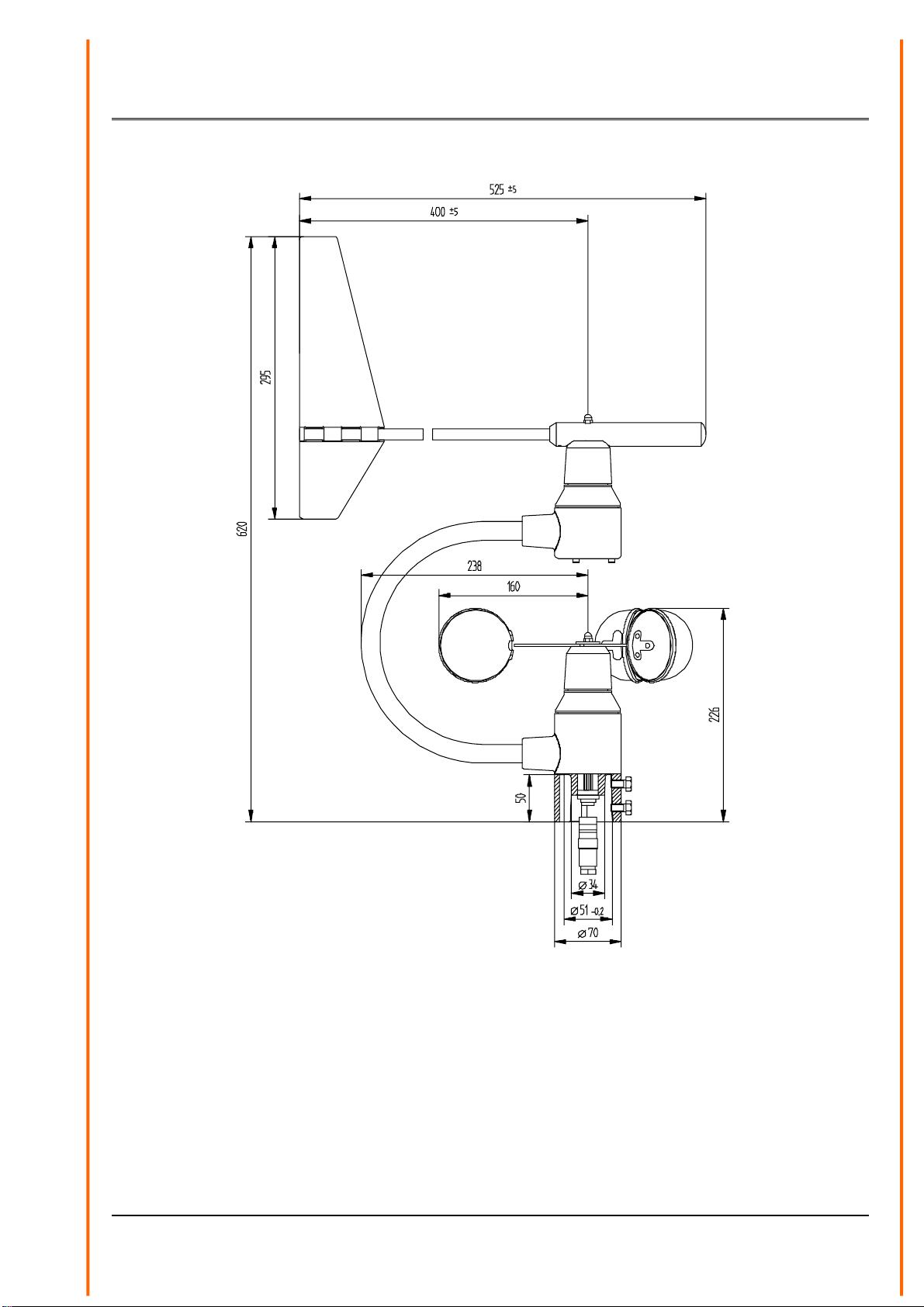
9 Dimensional Drawings
Figure 2: Dimension 4.3324.32.000
10 - 14 021591/02/09

Figure 3: Dimension 4.3324.32.001
11 - 14 021591/02/09

10 EC-Declaration of Conformity
Document-No.: 000439 Month: 02 Year: 09
Manufacturer: A D O L F T H I E S G m b H & C o. K G
Hauptstr. 76
D-37083 Göttingen
Tel.: (0551) 79001-0
Fax: (0551) 79001-65
Description of Product: Combined Wind Transmitter
Article No. 4.3324.32.000 4.3324.32.001 4.3324.32.900
4.3336.22.000 4.3336.22.001 4.3336.22.008 4.3336.32.000
4.3336.32.001 4.3336.32.008
specified technical data in the document: 021590/02/09; 021593/02/09; 021594/02/09;
The indicated products correspond to the essential requirement of the following European Directives and Regulations:
2004/108/EC DIRECTIVE 2004/108/EC OF THE EUROPEAN PARLIAMENT AND OF THE COUNCIL
of 15 December 2004 on the approximation of the laws of the Member States relating to
electromagnetic compatibility and repealing Directive 89/336/EEC
2006/95/EC DIRECTIVE 2006/95/EC OF THE EUROPEAN PARLIAMENT AND OF THE COUNCIL
of 12 December 2006 on the harmonisation of the laws of Member States relating to electrical
equipment designed for use within certain voltage limits
552/2004/EC Regulation (EC) No 552/2004 of the European Parliament and the Council of 10 March 2004
on the interoperability of the European Air Traffic Management network
(the interoperability Regulation)
The indicated products comply with the regulations of the directives. This is proved by the compliance with the following
standards:
Reference number Specification
IEC 61000-6-2: 2005 Electromagnetic compatibility
Immunity for industrial environment
IEC 61000-6-3: 2006 Electromagnetic compatibility
Emission standard for residential, commercial and light industrial environments
IEC 61010-1: 2001 Safety requirements for electrical equipment for measurement, control and
laboratory use. Part 1: General requirements
Place: Göttingen Date: 12.02.2009
This declaration certificates the compliance with the mentioned directives, however does not include any warranty of characteristics.
Please pay attention to the security advises of the provided instructions for use.
12 - 14 021591/02/09

13 - 14 021591/02/09

ADOLF THIES GmbH & Co. KG
Hauptstraße 76 37083 Göttingen Germany
P.O. Box 3536 + 3541 37025 Göttingen
Phone +49 551 79001-0 Fax +49 551 79001-65
- Alterations reserved-
14 - 14 021591/02/09
This manual suits for next models
1
Table of contents
Other ADOLF THIES Transmitter manuals

Popular Transmitter manuals by other brands

Audiovox
Audiovox PRO94BT2 Programming guide

Dometic
Dometic 9600000109 Installation and operating manual

Vector
Vector SDC-C1 quick start guide

Emerson
Emerson Micro Motion 1000 Series Configuration and Use Manual

Light Emotion
Light Emotion WDMX User instruction manual

Burg Wächter
Burg Wächter secuENTRY 5670 operating instructions


RF Technology
RF Technology Eclipse Series Operation and maintenance manual

FatShark
FatShark Byte Frost user manual

Silent Gliss
Silent Gliss SG 10303 operating instructions

Fire-Lite
Fire-Lite H350R Installation and maintenance instructions

Paradox
Paradox Magellan DCTXP2 user manual

Air-Bus
Air-Bus AB-TX owner's manual