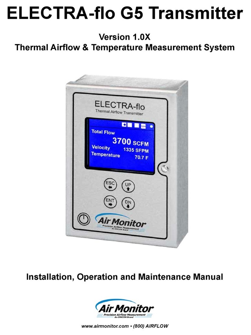
Air Monitor MASS-tron II/CEM User manual

Installation, Operation,
and Maintenance Manual
MASS-tron II/CEM
Microprocessor Based
Mass Flow "Smart" Transmitter
Versions 5.3X
Installation, Operation & Maintenance
Air Monitor Corporation provides complete
technical support between the hours of
7 a.m. and 5 p.m. PST, M-F
Contact our Service Department
Toll Free: 1-800-AIRFLOW
or fax us at 1-707-526-2825
Air Monitor Corporation
116-004-94.P65 (8-31-10)
MASS-tron II/CEM- IO&M Manual
Precision Airflow Measurement
An ON
I
CON Brand


MASS-tronII/CEM
Air Monitor Corporation
116-004-94.P65(8-31-10) MASS-tronII/CEM- IO&MManual
TABLEOFCONTENTS
INSTRUMENTWARRANTY ...................................................................................................................... i
SECTION1 –GENERALINFORMATION
1.1 DESCRIPTION ................................................................................................................................1
1.2 THEORYOFOPERATION .............................................................................................................. 1
SECTION2 –PERFORMANCE SPECIFICATIONS
2.1 TRANSMITTER ............................................................................................................................... 2
2.2 INDICATION..................................................................................................................................... 2
2.3 INPUTS/OUTPUTS .......................................................................................................................... 2
2.4 POWER .......................................................................................................................................... 2
SECTION3 –FEATURES
3.1 OPERATORSETUPMENU ............................................................................................................ 3
3.2 40CFR75COMPLIANT .................................................................................................................... 3
3.3 AIRDENSITYCORRECTION .......................................................................................................... 3
3.4 TRANSMITTERHOLD ..................................................................................................................... 3
3.5 AUTOMATICZEROING ................................................................................................................... 3
3.6 AUTO-purgeMANAGEMENT .......................................................................................................... 3
3.7 ALARM ........................................................................................................................................... 4
3.8 DATADISPLAY ............................................................................................................................... 4
3.9 K-FACTOR ...................................................................................................................................... 4
3.10 FLOW/DIFFERENTIAL/PRESSURECALCULATOR ........................................................................ 4
3.11 NETWORK...................................................................................................................................... 4
3.12 MULTIPLE OPERATING POWERSELECTIONS ............................................................................. 4
3.13 ENCLOSURE .................................................................................................................................. 4
SECTION 4 – INSTALLATION
4.1 RECEIVINGANDINSPECTION ....................................................................................................... 5
4.2 LOCATION ...................................................................................................................................... 5
4.3 MOUNTING ..................................................................................................................................... 5
4.4 PROCESSCONNECTIONS ......................................................................................................... 6-7
4.5 POWER/SIGNALCONNECTIONS ............................................................................................. 8-10
4.6 INPUT/OUTPUTSELECTION .........................................................................................................11
4.7 DISPLAYCONTRASTADJUSTMENT.............................................................................................11
TABLEOFCONTENTS

MASS-tronII/CEM
TABLEOFCONTENTS
SECTION5 – OPERATION
5.1 INTRODUCTION ............................................................................................................................ 12
5.2 START-UP ..................................................................................................................................... 12
5.3 NORMALOPERATION..............................................................................................................12-13
5.4 CONFIGURATION ......................................................................................................................... 14
5.5 PUSHBUTTONDEFINITION .......................................................................................................... 15
5.6 CONFIGURATIONPROGRAMMING..........................................................................................16-18
5.7 OPERATORPASSWORD SELECTION ........................................................................................ 19
5.8 TRANSMITTERSCALING&CONFIGURATION .........................................................................20-31
5.9 LOWPASS FILTER SELECTION .................................................................................................. 32
5.10 AUTO-zeroCONFIGURATION ....................................................................................................... 33
5.11 AUTO-purgeCONFIGURATION ..................................................................................................... 34
5.12 AUTO-calibrationCONFIGURATION ..........................................................................................35-36
5.13 ALARMCONFIGURATION ........................................................................................................37-38
5.14 CONTROLLERCONFIGURATION ................................................................................................. 38
5.15 SPECIALFUNCTIONCONFIGURATION ....................................................................................... 38
5.16 K-FACTORCONFIGURATION ...................................................................................................39-40
5.17 ENHANCEDDISPLAYCONFIGURATION..................................................................................41-44
5.18 ANALOGOUTPUTCONFIGURATION ........................................................................................... 45
5.19 TRANSDUCERSPANSELECTION ............................................................................................... 46
5.20 TRANSMITTERINPUTCALIBRATION ........................................................................................... 47
5.21 TRANSMITTEROUTPUTCALIBRATION ....................................................................................... 47
5.22 POWERSUPPLYCALIBRATION .................................................................................................. 47
5.23 TRANSDUCERCHARACTERIZATIONSELECTION....................................................................... 48
5.24 NETWORKCONFIGURATION....................................................................................................... 49
5.25 MENUINACTIVITYTIMEOUTSELECTION ................................................................................... 50
SECTION6 – CALIBRATION
6.1 REQUIREDEQUIPMENT .............................................................................................................. 51
6.2 PREPARATION ............................................................................................................................. 51
6.3 TRANSMITTERINPUTCALIBRATION .......................................................................................52-56
6.4 TRANSMITTEROUTPUTCALIBRATION ...................................................................................57-58
6.5 AUTO-spanPRESSUREREFERENCECALIBRATION ................................................................. 59
SECTION7 –MAINTENANCE ............................................................................................................... 60
SECTION8 –TROUBLESHOOTING .................................................................................................61-62
SECTION 9 – PARTS LIST................................................................................................................63-64
SECTION10 –CUSTOMER SERVICE .................................................................................................. 65
TABLEOFCONTENTS
Air Monitor Corporation
116-004-94.P65(8-31-10) MASS-tronII/CEM -IO&M Manual

MASS-tronII/CEM
Air Monitor Corporation
116-004-94.P65(8-31-10) MASS-tronII/CEM- IO&MManual
i
INSTRUMENT WARRANTY
NOTICEOF PROPRIETARYRIGHTS
This document contains confidential technical data, including
trade secrets and proprietary information which are the sole
property of Air Monitor Corporation. The use of said data is
solelylimited touseasspecifiedherein. Any otheruseisstrictly
prohibited without the prior written consent of Air Monitor
Corporation.
INSTRUMENTWARRANTY
AirMonitorCorporation(hereinafterreferred toas“Seller”)
warrants that at the time of shipment, products sold
pursuant to this contract will be free from defects in
materials and workmanship, and will conform to the
specifications furnished or approved in writing by Seller.
Nowarrantyis given thatdeliveredproducts will conform
to catalog sheets, data sheets, and the like, which are
subject to change without notice.
Seller will repair or replace, at its option, any products
listedunder thiswarranty whichis returnedfreight prepaid
toSellerwithin the earlier ofthree(3)years after start-up
or thirty-nine (39) months after shipment that, upon test
andexamination, provesdefectivewithin theterms ofthis
warranty. The warranty period for any item repaired or
replaced shall be for the time remaining on the warranty
periodofthe originalcomponents. Purchasershall notify
Seller in writing of such defect within sixty (60) days of
discoveryofthe defect.
This warranty does not extend to any product sold by
Seller which has been the subject of misuse, neglect,
accident, damage or malfunction caused by
interconnectionwithequipment manufactured byothers,
improper installation or storage, or used in violation of
instructionsfurnishedby Seller, nordoesitextend to any
product which has been repaired or altered by persons
notexpresslyapprovedbySeller. NordoesSellerwarrant
equipmentagainstnormaldeteriorationduetoenvironment;
noritemssuch aslamps,glass, and similaritemssubject
towearor burnoutthroughusage. Adjustmentsforitems
or equipment not manufactured by Seller shall be made
totheextentofanywarrantyofthemanufacturerorsupplier
thereof.
Seller shall not be liable for any special or consequential
damagesorforlossofdamage, directlyorindirectlyarising
from the use of the products. Seller's warranty shall be
limited to replacement of defective equipment and shall
notincludefield removal andinstallationexpenses.
Thewarrantysetforthaboveisinlieuofallotherwarranties
eitherexpressor impliedandconstitutes the fullextentof
Air Monitor Corporation’s liability to the customer, or any
otherpartyforbreachof warranty.
THEREARENO EXPRESSWARRANTIESEXCEPTAS
SET FORTH HEREIN AND THERE ARE NO IMPLIED
WARRANTIES OF MERCHANTABILITY OF FITNESS
FOR ANY PARTICULAR PURPOSE, WHICH ARE
PARTICULARLYDISCLAIMED.
MASS-tronII/CEM
Air Monitor Corporation
116-004-94.P65(8-31-10) MASS-tronII/CEM- IO&MManual
1 – GENERAL INFORMATION
1.1 – DESCRIPTION
The MASS-tron II/CEM is an ultra-low differential pressure "smart" massflow transmitter designed to convert the low
magnitude pressure signals generated by airflow probes, plus process temperature and static pressure inputs into
analogoutputsignals of massflow,temperature,pressure,and transmitter drift. EachMASS-tron II/CEMisequipped
with numerous standard features: Amulti-line LCD used during configuration/calibration and for display of process;
AUTO-zeroforelimination oftransmitter zeroerror;AUTO-caltomeasuretransmitterzeroandspandrift;userselectable
primarysignalnoise filter,inputpower isolation;capabilityof10:1flow or100:1pressure turndown;NEMA1enclosure,
and a long list of construction options.1.2 – THEORY OF OPERATION
Highandlow pressure signalsgeneratedby airflow stations orprobesact upon oppositesidesof a flexiblediaphragm
withinthe transducer. The differentialbetweenthetwo pressuresignalsdisplaces thediaphragm;the magnitudeofthe
displacementbeing measuredcreates anelectricalDCoutputfromthetransducer. Additional analogsignals ofprocess
temperature(viaexternal temperatureinput) and process static pressure(viainternalabsolute pressure transmitter)
aremadeavailable. Afterbeingmultiplexedand undergoingA/D conversion, theresultingdigital signalsrepresenting
process velocity pressure, temperature and static pressure can be manipulated within the microprocessor: square
rooted;densitycompensated for air temperatureandair pressure correction; scaledforunitsof measure andareafor
processoutputs;filtered and scaledforlocaldata displayandutilizedin performing a Special Function (see Section3
– Features). The built-in microprocessor runs the program that provides the following basic functions: Timing, logic,
mathematicaloperations, analoginputsignalmultiplexing,analog input/outputcalibration, digitalinput(contactclosure)
detection, output relay operation, automatic zeroing valve operation, Operator Setup menu system, display (LCD)
indication,andindividual LEDindication.
1
SECTION1 – GENERALINFORMATION

MASS-tronII/CEM
Air Monitor Corporation
116-004-94.P65(8-31-10) MASS-tronII/CEM- IO&MManual
2
2.3 – INPUTS/OUTPUTS
Analog Input. Analog input for temperature is available
andfieldconfigurableviajumper for0-5VDC,0-10VDC,or
4-20mADC.
Analog Outputs. Transmitter/AUTO-cal Reporting,
Temperature, Absolute Pressure, and one selectable
output areindividuallyconfigurableviajumperfor0-5VDC,
0-10VDC,or 4-20mADC.
Digital Inputs. Dry contacts input from "smart" relay for
AUTO-purgestartsignal andAUTO-calexternal start.
DigitalOutputs. Drycontactsfor optionalAlarmorAUTO-
purgeactivation/acknowledgment. Contactsareratedfor:
Maximum 3 amps @ 24 to 120VAC
Maximum 3 amps @ 24VDC
Maximum 0.5 amps @ 48VDC
Temperature Compensation Selection. Push-button
selectionoflinearized or non-linear input. Choiceof
thermocoupleor 100ohmplatinum RTDtemperature
sensor type.
TypeE -50to1750ºF -50to 950ºC
TypeT -50 to 750ºF -50 to 400ºC
TypeJ -50 to2000ºF -50to 1090ºC
TypeK -50to2000ºF -50 to1090ºC
RTD -50to1500ºF -50to 815ºC
Pressure Compensation. Absolutepressure
(atmospheric or duct static), up to 60 IN Hg.
Network Communication. Optional ModBus TCP/IP
overEthernet.
2.4 – POWER
PowerSupply.24VDC(20-40VDC)or 24VAC(20-28VAC).
Power Consumption. 18VA@24VAC,13VA@24VDC.
Circuit Protection. Power input is isolated, fused, and
reversepolarity protected.
2.1 – TRANSMITTER
Ranges.NaturalFullSpans
0 to 25.00 IN w.c.
0 to 10.00 IN w.c.
0 to 5.00 IN w.c.
0 to 2.00 IN w.c.
0 to 1.00 IN w.c.
Span Rangeability. The calibrated span can be down
rangedto40% of the NaturalSpan.
Accuracy.±0.1%of NaturalSpan,including non-
linearity, hysteresis, andnon-repeatability.
Stability. ±0.5% of Natural Span for six months.
Transducer Response Time. 0.5 second to reach
98% of a step change.
Temperature Effect. Zero. None;corrected byAUTO-
zero. Span. 0.015% of Full Span/ºF.
Mounting Position Effect.None; corrected byAUTO-
zero.
Span and Zero Adjustment. Digital, via internally
locatedpush-buttons.
Automatic Zeroing. Accuracy. Within 0.1% of
calibratedspan.Frequency. Every1to24 hours
selectableon1hourintervals.
Low Pass Filtration. Response time to reach 98% of a
step change is adjustable from 2.0 to 256.0 seconds.
Overpressure and Static Pressure Limit. 25 psig.
Temperature Limits. –20 to 180ºF Storage.
+40to140ºF Operating.
Humidity Limits. 0-95%RH,non-condensing.
2.2 – INDICATION
Displays. GraphicalbacklitLCD providesupto fivelines
of data display.
LED's indicate CPU Activated, AUTO-zero in Progress,
AUTO-zero over-ranged,AUTO-purge in Progress, and
AUTO-calinProgress.
SECTION2 – PERFORMANCESPECIFICATIONS
2 – PERFORMANCE SPECIFICATIONS
0 to 0.50 IN w.c.
0 to 0.25 IN w.c.
0 to 0.10 IN w.c.
0 to 0.05 IN w.c.
24VAC
24VDC
120VAC
14.4VA
9.6W
19.2VA
14VA
9.0W
18.67VA
85VA
37W
106VA
73VA
37W
92VA
Standard w/AUTO-purge
In Rush Contin In Rush Contin

MASS-tronII/CEM
Air Monitor Corporation
116-004-94.P65(8-31-10) MASS-tronII/CEM- IO&MManual
3 – FEATURES
3.1 – OPERATOR SETUP MENU
The microprocessor program contains a Operator Setup menu system for setting user selectable parameters. Four
pushbuttons,ESC, UP, DN, ENT,allowthe useraccessto themenufor settingconfigurationmodes andvalues. Refer
tothe ConfigurationProgramming(Section 5.6)instructionsfor operationdetails. Alsocontainedinthe OperatorSetup
menuisallinputandoutputcalibration. Thecalibrationmethodiscompletelydigitalandcontainsnoanalogpotentiometer
adjustmentswhich aresusceptibleto drift. Non-volatilememoryis usedforstoringallsetup parametersandcalibration
values,andwill remain unchangedafterset,even when powertotheunit is off.
3.2 – 40CFR75 COMPLIANT
The MASS-tron II/CEM is designed to provide all functions and meet all data reporting requirements specified under
40CFR75: signals(4-20mADCstandard;0-5Vor0-10Voptional) ofmassflowandtemperature;dailyAUTO-calreporting
of transmitter zero and span drift; dailyAUTO-purge of flow sensors;AUTO-purge in progress acknowledgment; and
AUTO-calinprogressacknowledgment. AUTO-calandAUTO-purgecyclescanbeinternallytimedorexternallyactivated,
withselectionvia Operator set-upmenu.
3.3 – AIR DENSITY CORRECTION
The MASS-tron II/CEM transmitter is capable of performing both process temperature and process static pressure
correction. Temperature inputisananalogsignal fromaremotetemperaturedevice; non-lineartemperature inputscan
belinearizedbythe microprocessor. Process static pressure ismeasuredbymeans of an internal absolute pressure
transmitter connected to the transmitter static pressure signal input.
3.4 – TRANSMITTER HOLD
Certain operations performed by the microprocessor place the unit into a Hold mode. This occurs when the Operator
Setupmenu systemis activated,when anAUTO-zeroisperformed,whenanAUTO-calisperformed,orwhenanAUTO-
purgecycleis in progress. WheninHold,all Normal mode processingishalted and outputsareheld at theirlastvalue
prior to Hold. Normaloperationis indicated by the"CPUActivated" LEDflashingata rate of fourtimespersecond. A
Hold mode is indicated by the "CPUActivated" LED flashing at a rate of one flash per second.
3.5 –AUTOMATIC ZEROING
At periodic intervals the microprocessor will automatically execute an AUTO-zero cycle consisting of the following
sequence: The transmitter output and display signals are put on Hold; a valve is activated which disconnects the
process high pressure from the high port of the transducer and connects the process static pressure to both sides of
the transducer, creating a true zero differential pressure; after a brief stabilization period, the transducer zero offset
signalis measuredandstoredinmemory;thevalveisdeactivatedandafterabrief periodfor processsignal stabilization,
theHold isreleasedand Normalprocess measurementresumes. During Normaloperation,thezerooffsetvaluestored
inmemoryis subtracted from subsequenttransducerreadingsuntil the nextAUTO-zerocycle occurs and repeatsthe
process. AUTO-zeroOn/Offand Intervalareavailable andconfigurableusing theOperatorSetup menu.
3.6 –AUTO-purge MANAGEMENT
For "dirty process air" applications requiring the use of an Air Monitor AUTO-purge system, the MASS-tron II/CEM
alongwitha "smart" relay providesthecapabilitiesof establishing purgefrequencyandduration, while also givingthe
userachoiceofeither internally timed cycle frequency orexternallytriggeredpurgeinitiation. During the purge cycle
all transmitter outputs are maintained at their last value prior to the start of the purge cycle.
3
SECTION 3 – FEATURES

MASS-tronII/CEM
Air Monitor Corporation
116-004-94.P65(8-31-10) MASS-tronII/CEM- IO&MManual
4
3.7 –ALARM
TheMASS-tronII/CEMAlarm Option providesthemeansfor having theprocesssignal comparedtoa user selectable
LowFlowalarm pointandautomatically activatesaForm Crelayto generate adrycontactalarm signal. Alarm On/Off,
Setpoint, Dead Band, and Delay are configurable via the Operator Setup menu. Alarm Setpoint can be displayed on
during Normal operating mode. AnAlarm Delay is available, if implemented (any time setting greater than zero), any
condition that would normally cause an alarm, triggers the delay timer first. If the alarm condition still exists after the
delay times out, then the alarm relay is activated.
3.8 – DATA DISPLAY
Theintegraldisplay isagraphical backlitLCD. It is capableof displayingthetransmitter flow,processtemperature and
static pressure signals in Engineering units, plus other signals of alarm orAUTO-cal functions. It can also display a
user settable I.D. number using any combination of standardASCII characters. It is also used by the Operator Setup
menufordisplaying the menu parametersandvalues. Configuringthe display for Normal operationisdoneusing the
OperatorSetupmenu.
3.9 – K-FACTOR
TheMASS-tronII/CEM isequipped withaK-Factor featurewhichallows fortheintroduction ofabias and/orgainfactor
into the transmitter's flow calculations. The K-Factor feature is intended to be used in two types of applications:
1. To adjustforflow measurementerror asaresult ofhighlydistorted airflowinducedby upstreamor downstreamflow
disturbances.
2. To adjust the transmitter's output to bring it into close correlation with field measured flow data.
TheK-Factorgain and biasvaluescan be entereddirectlyorthe MASS-tron II/CEMcancalculate these valuesbased
onmeasuredand referencevaluesfrom a1or 3pointairflow traverse.
3.10 – FLOW/DIFFERENTIAL PRESSURE CALCULATOR
TheMASS-tronII/CEMis equipped with an integralcalculatorfeaturethat allows the user todeterminethemaximum
flow or differential pressure from the appropriate variables. This feature allows the user to determine input or output
valuesatvarious pointsoftheprocess ornewvalues iftheprocess parametershavechanged. Also,the calculatorcan
beusedto implement asingle-pointdensity compensation foroperatingtemperatureand/or absolute pressure.
3.11 – NETWORK (option)
TheMASS-tronII canbeprovidedwith optionalModBusTCP/IP over Ethernetforserial data communication.
3.12 – MULTIPLE OPERATING POWER SELECTIONS
TheMASS-tronII/CEM can bepoweredby 24VACor 24VDC, or120VAC withoptionaltransformer.
3.13 – ENCLOSURE
TheMASS-tronII/CEM transmitterisfurnished inaNEMA 1 aluminumenclosure with external,unitaryplug interminal
strips for ease of installation and removal. An optional conduit connection box is available for applications requiring
enclosedfieldwiring.
SECTION 3 – FEATURES

MASS-tronII/CEM
Air Monitor Corporation
116-004-94.P65(8-31-10) MASS-tronII/CEM- IO&MManual
5
AllMASS-tronII/CEMsystemsaresuppliedtothe customer either rack mount or mounted in an enclosure. Because
each application is configured to specific customer requirements, previously submitted detail drawings should be
consultedwhenperformingSections 4.3, 4.4, and4.5.
Sections 4.4. and 4.5 contain generic information on the MASS-tron II/CEM transmitter. This information may not be
neededduringinstallation but willbeuseful in performingcalibrationand anytroubleshooting.
4.1 – RECEIVING AND INSPECTION
• Carefullyremove theMASS-tron II/CEMfromtheshippingcontainertakingESD(electrostaticdischarge)precautions.
• Inspect unit for any damage. Ifdamaged,contactfreight company.
• ReviewtheFactory SetupInformationSheet providedwith the unitand verify theW.O. # andSerial # matchthose on
theunit. Verify thattheconfigurationrecordedon theFactorySet-UpInformationSheet iscorrect foryourapplication.
Ifnot,contactAirMonitor'sCustomerService Departmentat 1-800-AIRFLOWforfurther guidance.
Note: The MASS-tron II/CEM has been configured and calibrated to customer specified parameters (see "Factory
Setup Information Sheet" provided with the unit), and requires no additional calibration/verification prior to
installation.
4.2 – LOCATION
• The MASS-tron II/CEM should be mounted in a location suitable for its enclosure/rack rating (review application
drawingsfor enclosurerating).
• The ambienttemperatureof the selectedmountinglocationmust be between40º– 140ºF. Considerationshould be
given to units exposed to direct sunlight.
• Theselectedmounting locationshouldbe rigid andfreeof vibration.
4.3 – MOUNTING
Refertoapplicable drawingsformounting the MASS-tronII/CEM.
• TheMASS-tronII/CEMcan be mounted in any positionprovideditis secured.
• Reasonableconsiderationshould be giventoclearances for pressureandelectrical connections.
4 – INSTALLATION
SECTION4 – INSTALLATION

MASS-tronII/CEM
Air Monitor Corporation
116-004-94.P65(8-31-10) MASS-tronII/CEM- IO&MManual
6
4.4 – PROCESS CONNECTIONS
The MASS-tron II/CEM comes standard with brass 1/8" FPT connections (or special fittings if ordered). To these
connections the customer can install fittings required for the type of tube/pipe used to connect to process sensor (i.e.
flowstation,flowprobe,static pressure sensors).
WhenconnectingtheMASS-tron II/CEM to anairflowmeasuringdevice, connections must becompletedasfollows:
– HighPorton MASS-tron II/CEM connectstoTotalPressure from airflowmeasuringdevice.
– LowPortonMASS-tron II/CEM connectstoStaticPressure from airflow measuringdevices.
Although any size of tube/pipe can be used, the response time of the MASS-tron II/CEM to process change may
increase if there is a increase in tube/pipe size or an increase in tube/pipe length.
CAUTION
– Selected fittings should be compatible with the brass 1/8" FPT bulkhead connection, and installed using an
appropriatethread lubricant/sealant.
– Whensignalfittings are added orremoved,use a 9/16 wrenchtopreventthe 1/8" FPTbulkheadfittingfrom
turning.
– It is extremely important that no pressure be present in signal tubing at the time of installation, and the
orientationofhighand low pressure signallinesismaintained between the sourceandtheMASS-tron II/CEM.
Figure4.1
SECTION4 – INSTALLATION
Mass Flow Transmitter
MC
AIR ONITOR ORPORATION

MASS-tronII/CEM
Air Monitor Corporation
116-004-94.P65(8-31-10) MASS-tronII/CEM- IO&MManual
7
4.4 – PROCESS CONNECTIONS (con't)
Ifprocessbeing measuredcontainshumidity ormoisture,it is recommendedadrip legwithdrain on eachtube/pipebe
installedtopreclude the migration ofwaterinto the MASS-tron II/CEM. SeeFigure4.2.for typical dripleginstallation.
Figure4.2
CAUTION
Migrationofwater into theMASS-tronII/CEM will void warranty.
SECTION4 – INSTALLATION

MASS-tronII/CEM
Air Monitor Corporation
116-004-94.P65(8-31-10) MASS-tronII/CEM- IO&MManual
8
SECTION4 – INSTALLATION
4.5 – POWER/SIGNAL CONNECTIONS
All power and signal wiring is done at the terminal strip at the left side of the MASS-tron II/CEM. Figure 4.3 below
represents the terminal strip and the connections for power input and the various inputs/outputs available (review
FactorySet-UpInformation Sheet for whichinputs/outputsare included with yourunit).
Figure4.3
CAUTION
When connecting or disconnecting any wiring to the MASS-tron II/CEM, the unit's power switch
(see Figure 4.1) must be in the OFF position.
WIRING.
It is recommended that any power wiring be 14 awg to 18 awg, and any signal wiring should be 14 awg to 22 awg. 14
awg is the maximum wire gauge that the terminal strip can accommodate.
No more than two wires should be connected to any one terminal. 18 awg is the maximum gauge wire that can be
doubledupin one terminal.
To facilitate wiring and any future removal of the MASS-tron II/CEM, each terminal strip is removable from the unit.
Remove terminal strip marked 1-16 first by pulling sideways, away from the unit. Aflat blade screwdriver can also be
used to gently pry strip free. Once the strip is removed, the second strip marked 17-32 can be similarly removed.
If the unit was furnished with optional conduit connection box, loosen screw, and remove cover to gain access to the
terminalstrip.
*USEDONLYWHENANOPTIONISPURCHASED

MASS-tronII/CEM
Air Monitor Corporation
116-004-94.P65(8-31-10) MASS-tronII/CEM- IO&MManual
4.5 – POWER/SIGNAL CONNECTIONS (con't)
Transmitter/AUTO-cal Reporting Output 1 (Terminals 1 and 3). Thisoutputissourced(powered)bytheMASS-tron
II/CEM.
4-20mADC: Maximum load resistance is 750 ohms.
0-10VDC: Minimum load resistance is 5000 ohms.
0-5VDC: Minimum load resistance is 2500 ohms.
Temperature Output 2 (Terminals 2 and 3). This output is sourced (powered) by the MASS-tron II/CEM.
4-20mADC: Maximum load resistance is 750 ohms.
0-10VDC: Minimum load resistance is 5000 ohms.
0-5VDC: Minimum load resistance is 2500 ohms.
Absolute Pressure Output 3 (Terminals 4 and 6). This output is sourced (powered) by the MASS-tron II/CEM.
4-20mADC: Maximum load resistance is 750 ohms.
0-10VDC: Minimum load resistance is 5000 ohms.
0-5VDC: Minimum load resistance is 2500 ohms.
Analog Output 4 (Terminals 5 and 6). This output is sourced (powered) by the MASS-tron II/CEM.
4-20mADC: Maximum load resistance is 750 ohms.
0-10VDC: Minimum load resistance is 5000 ohms.
0-5VDC: Minimum load resistance is 2500 ohms.
Temperature Input (Terminals 7, 8, and 10). Followtheappropriate figure belowforconnecting a temperatureinput
signal.
Figure4.4 Figure 4.5
AUTO-purge "Start" Signal (Terminals 11 and 13). Customertoprovide momentary(0.5to 10 secondunpowered)
dry contact as notification of AUTO-purge cycle initiation (typically from "smart" relay). Upon receiving this signal,
transmitterholdwill be activated.
ExternalAUTO-cal Start (Terminals 12 and 13). Customerto providemomentary(0.5to10 second unpowered)dry
contact to initiateAUTO-cal cycle.
Input Power (Terminals 14, 15, and 16). Power required by MASS-tron II/CEM must be connected to Terminals 15
and16. Earthgroundshould beconnectedtoTerminal14.Whenpoweringmultiple unitsfromonepowersource,polarity
mustbemaintained.
Low Flow Alarm (Terminals 21, 22, and 23). Customer to connect according to desired alarm logic. Figure 4.3
indicatesde-energized(alarm off)state.
ReviewFactory Set-UpInformationSheet
for your signal type.
ReviewFactory Set-UpInformationSheet
for your signal type.
ReviewFactory Set-UpInformationSheet
for your signal type.
ReviewFactory Set-UpInformationSheet
for your signal type.
SECTION4 – INSTALLATION
9

MASS-tronII/CEM
Air Monitor Corporation
116-004-94.P65(8-31-10) MASS-tronII/CEM- IO&MManual
10
4.5 – POWER/SIGNAL CONNECTIONS (con't)
AUTO-cal in Progress (Terminals 24, 25, and 26). Acknowledgment contactfor customeruse. SeeSection 5.12 for
contact logic.
AUTO-purge "IN PROGRESS" (Terminals 29 and 30). Acknowledgment contactfor customer use. Contactsclose
uponAUTO-purgecycle initiation,remainclosed throughtheprogrammed PurgeDuration.
SECTION4 – INSTALLATION

MASS-tronII/CEM
Air Monitor Corporation
116-004-94.P65(8-31-10) MASS-tronII/CEM- IO&MManual
SECTION4 – INSTALLATION
11
4.6 – INPUT/OUTPUT SELECTION
Selectionsofinput and output signaltypesare made ontheJumpersection of theI/Oboard,see Figure 5.2. Remove
top cover to gain access to the Jumpers. Figure 4.7 depicts the Jumper board and the pins associated with specific
input and output signal types.
Figure4.7
Table 4.1 lists the identifier for each row of pins to be jumpered for a specific input or output signal type.
Table 4.1
Thenecessaryjumpers havebeeninstalled at theFactoryfor customerspecifiedinputs and outputs(seeFactory Set-
UpInformationSheet). The availability ofinputsand outputs dependsonoptions purchased.
To changethesignaltypeofanavailable inputor output,removealljumpersfromthepresent signaltype pinsand install
them on the desired signal type pins.
Inputshavea singlejumpercovering two pins,andoutputs have twojumperscovering fourpins.
4.7 – DISPLAY CONTRAST ADJUSTMENT
To compensate for different ambient lighting conditions and viewing angles, the MASS-tron II/CEM display's contrast
canbeadjustedfor optimum visibility.
Contrast is adjusted using potentiometer R1 on CPU board (see Figure 5.1). To gain access to R1:
• Removethetwo 10-32 screws fromfrontcover and pull thecoverstraightup and totheright.
• TurnR1 clockwisetoincrease contrast(darken charactersrelativetobackground)and counterclockwisetodecrease
contrast.
AnalogOutput(AO-1)
(TransmitterAUTO-calReporting)
AnalogOutput(AO-2)
(Temperature)
AnalogOutput(AO-3)
(AbsolutePressure)
AnalogOutput(AO-4)
(Selectable)
AnalogInput (AI-1)
(Temperature)
AnalogInput (AI-2)
(NotUsed)
4 to 20mADC
J10
J7
J4
J1
J16
J13
0 to 5 Volts
J11
J8
J5
J2
J17
J14
0 to 10 Volts
J12
J9
J6
J3
J18
J15
SIGNALTYPE

MASS-tronII/CEM
Air Monitor Corporation
116-004-94.P65(8-31-10) MASS-tronII/CEM- IO&MManual
5.1 – INTRODUCTION
TheMASS-tronII/CEM hasbeenconfigured andcalibratedat the Factorytocustomer specifiedparameterswhich are
recordedonthe MASS-tron II/CEM FactorySet-UpInformation Sheet, includedwiththeunit. Review this information
and verify that the MASS-tron II/CEM setup is correct for your applications. If any problems or discrepancies are
detected,contactAirMonitor'sCustomerService Departmentat 1-800-AIRFLOW priortoproceeding.
5.2 – START-UP
1. AfterInstallation has beenverifiedinaccordance with Section4,turn power switchlocatedatthe lower leftsideto
theONposition(seeFigure4.1).
2. Display will briefly indicate:
MASS-tron II/CEM
Thanks for Choosing
AIR MONITOR with the progressing from left to right.
Followedby:
MASS-tron II
PerformingAuto-Zero
Afterapproximately10 seconds,and thenreturntoNormal displaymode,andgreenLEDindicating"CPUActivated"
willflashrapidly (4 times persecond). Thisis Normal operation mode andnofurther user interface isrequired. If,
however, user would like to verify configuration or change user controlled parameters, continue to Section 5.4
entitled"CONFIGURATION".
5.3 – NORMAL OPERATION
UnderNormaloperation the MASS-tronII/CEM'sdisplay willcontinuouslyindicate currentprocessvariables andother
parametersselected.
AUTO-zero. At periodical intervals* (see Factory Set-Up Information Sheet) the AUTO-zero cycle will be initiated.
When this occurs, the display will be frozen and all outputs will remain constant. During this cycle the "AUTO-zero in
Progress" LED will be lit.
Thiscyclewill not occur ifAUTO-zerohasbeen turned OFF inconfigurationprogramming(see Section 5.10).
The AUTO-zero cycle can be manually activated by user (if ON in configuration programming) by simultaneously
pressingESC andUP,then scrolling until PerformAUTO-zerois displayed, thenpressENT.
If"AUTO-zeroInProgress" LEDremainson, continuouslyorflashes rapidly, refertoSection 8-Troubleshootingforthe
requiredaction.
12
SECTION5 –OPERATION
5 – OPERATION

MASS-tronII/CEM
Air Monitor Corporation
116-004-94.P65(8-31-10) MASS-tronII/CEM- IO&MManual
13
5.3 – NORMAL OPERATION (con't)
AUTO-purge. AUTO-purge cyclewillbe activated atperiodicintervals determined by the"smart"relay programming.
When activated, display will be frozen and all outputs will remain constant. During this cycle, the "AUTO-purge In
Progress"LED willremainlit. Length ofcycledepends onpurgeduration andafter-purge duration(seeFactory Set-Up
InformationSheet).
Thiscyclewill not occur ifAUTO-purgehasbeen turned OFFinconfigurationprogramming (see Section5.11).
AUTO-cal. Every 24 hours* or when externally activated, theAUTO-cal cycle will be initiated. When this occurs, the
display will be frozen and all outputs will remain constant (Note: Transmitter/AUTO-cal Reporting Output 1 will vary
during the reporting phase of theAUTO-cal cycle. See Section 5.12 for more specific details).
DuringtheAUTO-calcycle, theMASS-tron II/CEMwillfirstperformanAUTO-zerocyclewhichcreatesazerodifferential
pressure across the transducer. Any zero signal error is measured and stored.
Upon completion of the AUTO-zero cycle, the MASS-tron II/CEM performs an AUTO-span cycle which creates a
percent (see Factory Set-Up Information Sheet) of full scale differential pressure across the transducer. Any span
signalerroris measured and stored.
The remainder of the AUTO-cal cycle consists of: Start Report Delay; Zero Report Duration, In Between Report
Duration;andSpanReport Duration–all of whichhaveuser selectabledurations.
During theAUTO-cal cycle, the "AUTO-cal In Progress" LED will be lit.
TheAUTO-cal cycle can be manually activated by user by simultaneously pressing ESC and UP, then scrolling until
PerformAuto-Calib.isdisplayed, then press ENT.
If the "AUTO-cal In Progress" LED remains lit after completion of the AUTO-cal cycle, the error between the input
reference pressure and the reference value (see Section 5.15) is 3% to 5%. If the LED flashes rapidly, the error is
greaterthan5%. Refer to Section 8–Troubleshootingfor the required action.
Additionally, if the "AUTO-zero In Progress" LED remains lit or flashes rapidly after completion of theAUTO-cal cycle
(seeAUTO-zeroabove formeaning)refer toSection8 –Troubleshootingforthe requiredaction.
ALARMS. If alarm has been turned on in Configuration Programming and process conditions exist to activate the
alarm, the alarm relay will be energized (after set delay time).
*Note:
Theintervalclock forAUTO-zero,AUTO-purge,andAUTO-calcycles is initiatedwhentheMASS-tron II/CEM's power
switch is turned on. The time intervals (preset in Operator Set-Up menu) will then start their timing sequence.
To reset theinterval clock,turnpower offfor aminimum of10seconds, thenturnpower backon. Intervalclock willthen
initiate at time zero.
Changing the interval selection in Operator Setup does not reset time clock.
SECTION5 –OPERATION

MASS-tronII/CEM
Air Monitor Corporation
116-004-94.P65(8-31-10) MASS-tronII/CEM- IO&MManual
14
SECTION5 –OPERATION
5.4 – CONFIGURATION
TheMASS-tron II/CEM'sonboardmicroprocessor controlsConfiguration: Operatingparameter selection;input/output
activationandscaling, display scaling, and transducercalibration.
Thecustomercan verify configuration and changecertainparameters (within defined ranges)byenteringthe MASS-
tronII/CEM'sConfigurationmode.ThisisaccomplishedusingthefourpushbuttonslocatedontheMASS-tronII/CEM'stop
cover.
Thetype(i.e., 4-20mA, 0-5V, 0-10V) ofavailableoutputs can also bechangedbyjumper selections onI/Oboard(see
Section 4.6).
To gain accesstothe jumpers, remove two10-32screws on frontcoverand pull thecoverstraightup and swingtothe
right..
CAUTION: Withcoverremoved, ESD (electrostatic discharge)precautionsshouldbe observed at alltimesto
protectsensitivecomponents.
RefertoFigure 5.1 for locationofpushbuttons: UP, DN, ESC, ENT, and Figure5.2for location of jumperboard.
Figure5.1
Figure5.2

MASS-tronII/CEM
Air Monitor Corporation
116-004-94.P65(8-31-10) MASS-tronII/CEM- IO&MManual
15
SECTION5 –OPERATION
5.5 – PUSHBUTTON DEFINITION
Inadditionto Configurationprogramming,pushbuttons canbeused for certainfunctions when intheNormal operation
mode. The following list describes the pushbutton function when in the Normal operation mode and in the Operator
Setup(programming).
When in Normal Operation Mode.
ESC + ENT ActivatestheOperator Setup menu.
ESC + UP Displays a list of Manual Actions available on the top line of the display. Use UP or DN to scroll
throughselections.
Thefollowinglist describes all possibleactions. Thoseavailabledepend on installed options.
–TurnOnAutoSpanVlv Outputnotheld.
–Turn OnAutoZeroVlv Outputnotheld.
–PerformAuto-Zero Outputheld.
–PerformAuto-Calib. Output held.
UP + DN Displays software Version, W.O. #, S/N, and ID.
When in Operator Setup.
UP orDN Use to scroll to the desired Main Menu item.
Use to scroll to the value or mode within a Parameter.
ENT Enters user into specific selection sub-menu from Main Menu Selection.
Displayscurrentsettingof selected Parameter.
Enterstheselectedvalueormodeinto memory.
ESC Use to exit Main Menu selection to avoid scrolling to "Return to MAIN MENU".
The following pushbutton combinations can be used to more quickly set user selected values (i.e. display zero and
span, K-factor, Scaling Values, etc.).
UP* + ESC Increasethesecondcolumndigit.
DN* + ESC Decrease the second column digit.
UP* + DN Increasethethirdcolumndigit. XXXXX
DN* + UP Decrease the third column digit.
UP* + ESC and DN Increase the fourthcolumndigit.
DN* + ESC and UP Decrease the fourthcolumndigit.
*Mustbepressed and heldbeforeotherbutton(s) are pressed.
2ndColumn
3rdColumn
4thColumn
NOTE
Pushbuttons are momentary type and should be quickly pressed and released to
initiate desired change, unless otherwise instructed to press and hold.
Table of contents
Other Air Monitor Transmitter manuals

Air Monitor
Air Monitor ELECTRA-flo G5 User manual

Air Monitor
Air Monitor VELTRON III User manual

Air Monitor
Air Monitor AUTO-purge III User manual

Air Monitor
Air Monitor VOLU-flo/OAM II User manual

Air Monitor
Air Monitor VELTRON DPT 2500 User manual

Air Monitor
Air Monitor VELTRON II User manual

Air Monitor
Air Monitor ELECTRA-flo G5 User manual