ADOR RK3000 User manual

RK3000
High Frequency Power Supply
Microprocessor Transformer Control
for Electrostatic Precipitators
ADOR POWERTRON LIMITED
RAMNAGAR COMPLEX,
PLOT NO 51, D-II BLOCK,
MIDC, CHINCHWAD,
PUNE 411019
INDIA
Version 1.02
DRG NO: 5003-0004-13-06/1

RK3000 High Frequency Power Supply
Operating Manual
Page 2 of 73
TABLE OF CONTENTS
INTRODUCTION:MAXIMUM FLEXIBILITY WITH MINIMUM EMISSIONS.......................................................5
CHAPTER 1 COMPONENTS AND CONFIGURATIONS ...............................................................................6
Major System Components................................................................................................................................................6
Keypad and Display Unit........................................................................................................................................6
Control Unit .............................................................................................................................................................7
Control Communications Cable.............................................................................................................................8
Current Transformer..............................................................................................................................................8
Potential Transformer.............................................................................................................................................9
Secondary Signal Conditioning Resistors..............................................................................................................9
QUICK START CHART.................................................................................................................................... 10
For One-to One System Configuration................................................................................................................ 10
QUICK START CHART.................................................................................................................................... 11
For One-to-Many System Configuration............................................................................................................. 11
CHAPTER 2 OPERATING PARAMETERS AND FEATURES.................................................................... 12
DEFINITIONS OF PROGRAMMABLE PARAMETERS...............................................................................12
Average Readings.................................................................................................................................................. 13
Coordination System ............................................................................................................................................. 13
Definition of Control Responses........................................................................................................................... 13
Display ID............................................................................................................................................................... 13
Energy Management (Mgt) Setup (Optional Feature)....................................................................................... 13
External Alarm/Trip ............................................................................................................................................. 13
External Alarm Message Text ..............................................................................................................................14
Max Set Size........................................................................................................................................................... 14
Pedestal Rate.......................................................................................................................................................... 14
Phase Back ............................................................................................................................................................. 14
Power Down Rapping............................................................................................................................................14
Pre-Spark Readings............................................................................................................................................... 14
Primary Current Limit .........................................................................................................................................14
Primary Voltage Limit.......................................................................................................................................... 14
Process Sense.......................................................................................................................................................... 14
Quench Mode......................................................................................................................................................... 15
Quench Time.......................................................................................................................................................... 15
Ramp Rate.............................................................................................................................................................. 15
Rapping System Set-up ......................................................................................................................................... 15
Re-initialize............................................................................................................................................................. 15
Relay Timers.......................................................................................................................................................... 15
Conduction Display ...............................................................................................................................................15
Secondary Current Limit...................................................................................................................................... 16
Secondary Voltage Limit....................................................................................................................................... 16
Spark and Arc Control Response......................................................................................................................... 16
Spark Rate Control ...............................................................................................................................................16
Spark Sensitivity.................................................................................................................................................... 16
Soft Arc................................................................................................................................................................... 16
Software Version.................................................................................................................................................... 16
Under Voltage Trip –Primary / Secondary ........................................................................................................ 16
Under Voltage Timer.............................................................................................................................................16
DEFINITION OF NON-PROGRAMMABLE FEATURES.............................................................................. 17
Arc Numerical Display..........................................................................................................................................17

RK3000 High Frequency Power Supply
Operating Manual
Page 3 of 73
Automatic Display Calibration............................................................................................................................. 17
IGBT Firing Delay................................................................................................................................................. 17
Soft Start................................................................................................................................................................. 17
Spark Indicator and Numerical Display.............................................................................................................. 17
True RMS Primary Voltage and Current Displays............................................................................................ 17
Manual Control...................................................................................................................................................... 17
Non-Volatile Memory............................................................................................................................................ 17
Watt Meter.............................................................................................................................................................17
CHAPTER 3 DIGITAL DISPLAY.................................................................................................................. 18
Device Selection Screen.........................................................................................................................................18
Device Status Screen..............................................................................................................................................18
Electrical Reading Screen ..................................................................................................................................... 18
Prompt Screen........................................................................................................................................................19
Parameter Screen ..................................................................................................................................................19
Alarm Summary Screen........................................................................................................................................ 19
CHAPTER 4 KEYPAD DESCRIPTION ........................................................................................................ 21
CHAPTER 5 PROGRAMMING INSTRUCTIONS........................................................................................ 24
Viewing Parameters...............................................................................................................................................24
Security Programming Code Entry .....................................................................................................................24
ID Set-Up................................................................................................................................................................ 25
Coordination System ............................................................................................................................................. 26
Programming Discrete Key Parameters.........................................................................................................................27
Limits key............................................................................................................................................................... 27
RAMP.....................................................................................................................................................................29
PHASE BACK ....................................................................................................................................................... 29
PED......................................................................................................................................................................... 29
QUENCH................................................................................................................................................................ 30
PROMPT................................................................................................................................................................ 30
Clear Alarm............................................................................................................................................................ 30
Programming “Prompt Key” Parameters......................................................................................................................31
PROMPT Key........................................................................................................................................................ 31
Average Readings.................................................................................................................................................. 31
Pre-Spark Readings............................................................................................................................................... 32
Conduction Display ...............................................................................................................................................33
Spark Rate Control ............................................................................................................................................... 33
Quench Mode......................................................................................................................................................... 34
Process Sense.......................................................................................................................................................... 35
Reinitialize Interface Unit..................................................................................................................................... 35
Reinitialize Keyboard and Display Unit .............................................................................................................. 36
Software Version.................................................................................................................................................... 37
Max Set Size........................................................................................................................................................... 37
External Alarm Trip.............................................................................................................................................. 39
External Alarm Message Text ..............................................................................................................................40
Under Voltage Setup..............................................................................................................................................42
Energy Mgt Setup..................................................................................................................................................43
Wet Precipitator Wash Down System.................................................................................................................. 44
Power Down Rapping............................................................................................................................................44
Rapping System Set-up for Motor Timers (Option)........................................................................................... 45
Spark Sensitivity.................................................................................................................................................... 45
Soft Arc Detection.................................................................................................................................................. 46
Switching to Manual Operation ...........................................................................................................................46
CHAPTER 6 AIR LOAD INSTRUCTIONS ................................................................................................... 48
Pre-Operating Checkout:...................................................................................................................................... 48

RK3000 High Frequency Power Supply
Operating Manual
Page 4 of 73
CHAPTER 8 GAS LOAD ADJUSTMENTS.................................................................................................. 50
Normal Operation.................................................................................................................................................. 50
High –Resistivity Ash Operation......................................................................................................................... 50
Process Upset Operation.......................................................................................................................................50
CHAPTER 9 OPTIMIZING THE RK3000 PRECIPITATOR CONTROL OPERATION................................ 51
CHAPTER 10 DISCUSSION OF TYPICAL CONTROL WAVEFORMS........................................................ 52
Waveform #1, Quench Mode, Arc Only, Pedestal Programmed to 1 Cycle.....................................................52
Waveform #2, Quench Mode, Arc Only, Pedestal Programmed to 5 Cycles ...................................................53
Waveform #3 and #4, Quench Mode, Arcs and Sparks, Pedestal Programmed to 1 and 10 Cycles ..............54
Waveforms #5 and #6, Automatic Parameter Adjustment with Sparking and Arcing................................... 55
Waveform #7, Typical Control Waveform.......................................................................................................... 56
Waveforms #8 and #9, Back Corona Control ..................................................................................................... 57
CHAPTER 11 DESCRIPTION OF INTERFACE UNIT CONNECTIONS, LEDS, AND RELAYS.................. 58
CHAPTER 12 TECHNICAL HELP ................................................................................................................. 59
WARRANTY RETURN AUTHORIZATION................................................................................................... 60
APPENDIX I –WET PRECIPITATOR WASH DOWN SYSTEM (OPTIONAL FEATURE) ............................. 61
Wet Precipitator Wash Down System Timer.................................................................................................................61
APPENDIX II –TIMERS FOR MOTOR OPERATED CLEANING DEVICES (OPTIONAL FEATURE).......... 64
Motor Operated Electrode Cleaning Equipment Timers .............................................................................................64
APPENDIX III –LIST OF ALARM TEXTS ....................................................................................................... 67
TABLE 1 PREPROGRAMMED LEVELS AND OPERATING RANGES............................................... 68
INDEX QUICK REFERENCE .................................................................................................................. 69

RK3000 High Frequency Power Supply
Operating Manual
Page 5 of 73
INTRODUCTION: Maximum Flexibility with Minimum Emissions
Ador’s RK3000 High Frequency transformer-rectifier control is designed specifically for
use on electrostatic precipitators.
An extremely high degree of control flexibility is available through the RK3000’s many
easily programmed operating parameters and automatic features. This flexibility, in turn,
results in maximum precipitator efficiency and minimum outlet emissions.
This manual will define all the pre-programmed and field programmable features of the
RK3000 control, as well as provide a description of the control components. A description
of typical waveforms, and suggestions for optimizing the control’s operation, are also
included.
RK3000 High Frequency Power Supply
Operating Manual
Page 6 of 73
CHAPTER 1 COMPONENTS AND CONFIGURATIONS
Major System Components
The following descriptions and pictures are presented to familiarize the user with the six
components that make up the RK3000 High Frequency transformer-rectifier control: The
photos shown are typical and may vary slightly from those shown.
The following is a list and definition of the major control components.
oKeypad and Display Unit
oControl Unit
oInterface Communications Cable
oCurrent Transformer
oPotential Transformer
oSecondary Signal Conditioning Resistors
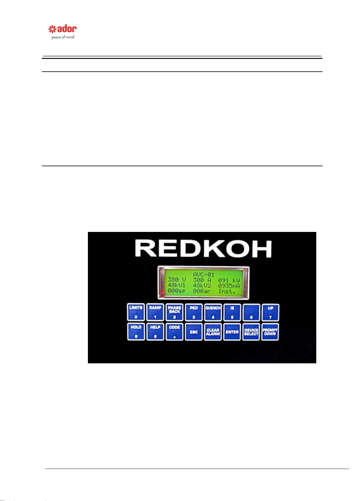
Keypad and Display Unit
The Keypad and Display Unit is the user interface to the various operating modes and
variable parameters of the system. It communicates with one or more Interface Boards.
Electrical readings, programming screens, alarm messages, operating messages, and
communication information, are displayed on the face of this unit. A keyboard, for
programming purposes, is also located on the face of this unit.
Figure 1: Keypad and Display Unit

RK3000 High Frequency Power Supply
Operating Manual
Page 7 of 73
Control Unit
The Control Unit is the interface between the analog and digital signals present in the
control and feedback circuits. The IGBT firing circuit is located on this Unit. It responds
to precipitator operating conditions based on the parameters programmed into the
Keyboard and Display Unit. The switches for setting the Control Unit ID number are
also located on this Unit.
Figure 2: Control Unit

RK3000 High Frequency Power Supply
Operating Manual
Page 8 of 73
Control Communications Cable
This cable is used between the Keypad and Display Unit, and the Control Unit to provide
a communications link for passing data.
Figure 3: Control Communications Cable
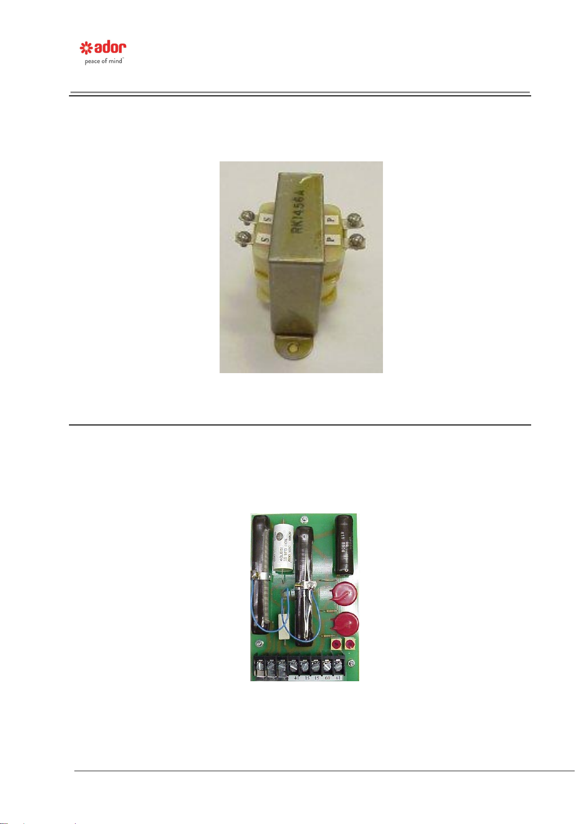
Current Transformer
The Current Transformer (CT) and load resistor combination, when properly set, provides
a 5V signal, at rated current, to the Control Unit. The signal is used for primary current
display and limit.
Figure 4: Current Transformer
RK3000 High Frequency Power Supply
Operating Manual
Page 9 of 73
Potential Transformer
The Potential Transformer (PT) measures the transformer primary voltage and provides a
reference signal to the Control Unit. The PT has a ratio of 600 volts to 20 volts. The
signal is used for primary voltage display and limit.
Figure 5: Potential Transformer
Secondary Signal Conditioning Resistors
Signal conditioning resistors are provided for both the secondary current and secondary
voltage reference signals. Their values will vary depending on the transformer-rectifier
rating. See schematic diagrams for proper values. These signals are sent to the Control
Unit for secondary voltage and current display and limits, as well as spark pickup. Full
scale is represented by a 5V signal.
Figure 6: Secondary Signal Conditioning Resistors

RK3000 High Frequency Power Supply
Operating Manual
Page 10 of 73
QUICK START CHART
For One-to One System Configuration
(See page 24)
A one-to-one system configuration is defined as a system where there is
one Keypad and Display Unit, and one Control Unit physically installed
on each control cabinet. If you have more than one Keypad and Display
Unit associated with more than one Control Unit see the Quick Start Chat
for a One-to Many Configuration (next page).
Not all parameters and operating modes need to be programmed in order
to get the control(s) up and running. To get started quickly, for each
control cabinet, follow the instructions in the order that they appear
below.
1. Enter the Programming security code (page 24).
2. Program the Max Set Size (page 41).
3. Program the Limits (page 27).
The other parameters and operating modes have default values, based
on typical precipitator operation. They will allow the control and
precipitator to operate, but at less than optimum efficiency. All default
values should be reprogrammed, as needed, to optimize the precipitator
efficiency and minimize outlet emissions.
At this point all the control IDs and Names will be the same. Reprogram
the control ID set-up (page 25) to give each TR control a unique name, if
desired.

RK3000 High Frequency Power Supply
Operating Manual
Page 11 of 73
QUICK START CHART
For One-to-Many System Configuration
(See page 24)
A one-to-many system configuration is defined as a system where there
is one or more Keypad and Display Units communicating with one or
more Control Units, regardless of location. If you have only one Keypad
and Display Unit associated with only one Control Unit see the chart for
the One-to-One configuration.
Not all parameters and operating modes need to be programmed in order
to get the control(s) up and running. To get started quickly follow the
instructions in the order that they appear below. This must be done
for each Keypad and Display Unit and each Control Unit (control
cabinet), as applicable.
1. Enter the security code (page 26).
2. Follow the ID set-up on page 25.
3. Program the Max Set Size (page 37).
4. Program the Limits (page 27).
The other parameters and operating modes have default values, based
on typical precipitator operation. They will allow the control and
precipitator to operate, but at less than optimum efficiency. All default
values should be reprogrammed, as needed, to optimize the precipitator
efficiency and minimize outlet emissions.

RK3000 High Frequency Power Supply
Operating Manual
Page 12 of 73
CHAPTER 2 OPERATING PARAMETERS AND FEATURES
The following is a list of the operating parameters and features incorporated in the
RK3000 control. This list is followed by definitions (broken into programmable and non-
programmable groups), and later in this manual, detailed instruction on how the
parameters are programmed.
Arc Numerical Display
Automatic Display Calibration
Average Readings
Coordination System
Display ID
Energy Management Setup
External Alarm/Trip
External Alarm Message Text
Instantaneous Kilowatt Display
Manual Control
Message Display
Nonvolatile Memory
Pedestal Rate
Phase Back
Power Down Rapping
Pre-Spark Readings
Primary Current Limit
Primary Voltage Limit
Process Sense
Quench Mode
Quench Time
Ramp Rate
Rapper System Set-up
Reinitialize Control Unit
Reinitialize Keypad and Display Unit
Relay Timers
Conduction Display
Secondary Current Limit
Secondary Voltage Limit
Separate Spark and Arc Control Responses
Soft Start
Soft Arc Detection
Spark Numerical Display
Spark Sensitivity
Spark Rate Control
Efficiency Display
True RMS Primary Voltage & Current Display
Under Voltage Time Delay
Under Voltage Trip –Primary
Under Voltage Trip –Secondary
DEFINITIONS OF PROGRAMMABLE PARAMETERS
The following definitions explain the programmable parameters available in the
microprocessor transformer-rectifier control. Programming instructions are presented
later in this manual. All programmable parameter values are entered into control memory
through a 16-key, sealed membrane, dual-function keypad located on the control panel
door (see page 21).
To prevent tampering with the control, a four-digit security programming access code is
required to gain access to the programming mode (see page 24).

RK3000 High Frequency Power Supply
Operating Manual
Page 13 of 73
Average Readings
For situations where the process being controlled is highly erratic or fluctuates a great
deal, the display can be programmed to show average electrical readings over a 5
second time period. This smoothes the display movement and makes it easier to read.
Coordination System
Timer relays are an optional feature of the control system. When timer relays are
supplied, their operation must be coordinated so that, if desired, multiple relays are not
operating at the same time. This only affects systems that are using the relays for
operating motor driven rapping systems or wet precipitator wash down systems.
Definition of Control Responses
A transformer-rectifier will operate at its rated current or voltage levels unless the
microprocessor transformer control circuitry detects a transient. When a transient is
detected, the control automatically takes action to lower the operating levels of voltage
and current.
The types of transients that the control detects are:
Spit –Low current, fast rise time electrical discharge that extinguishes itself
instantaneously. Due to self-extinguishing characteristics, the RK3000 takes no control
action when a spit is detected.
Spark –Low current, relatively slow rise time electrical discharge that persists for one half
cycle or less before extinguishing. The control phases back (reduces) the power for this
condition.
The spark rate that is displayed in the Electrical Reading Screen is a sixty (60) second
rolling average of these spark occurrences.
Arc –High current electrical discharge that persists for great than one-half cycle and
usually requires removal of electrical power before it will extinguish. The control
quenches (turns off) the power for this condition.
The arc rate that is displayed in the Electrical Reading Screen is a sixty (60) second
rolling average of these arc occurrences.
Display ID
In order for information to be properly transferred between the Keypad and Display Unit
and the Control Unit, over the communications system, each Keypad and Display Unit
must have a unique ID number.
Energy Management (Mgt) Setup (Optional Feature)
If your control system is communicating with a Transceiver(communication gateway
between TR, Rapper, and Central controls), and the optional Energy Management
System has been included in the Transceiver, the control can be assigned to one of four
independent energy management systems. And within each energy management system
the control can be assigned to a particular electrical field.
External Alarm/Trip
There are four (4) external alarm inputs (Alarm 1 through Alarm 4) that can be used to
connect normally closed alarm contacts for such things as high TR temperature, high/low
TR oil level, full hopper condition, drag conveyor failure, high O2, or any other condition
where a TR alarm or trip may be desired.

RK3000 High Frequency Power Supply
Operating Manual
Page 14 of 73
External Alarm Message Text
In conjunction with the external alarm inputs, there are preprogrammed tags
(descriptions) that can be assigned to each input. .
Max Set Size
The same microprocessor control components are used regardless of the size of the TR
they are connected to. In order for the control to know what size TR it is connected to,
the TR name plate ratings are field programmed into the control in a programming screen
called Max Set Size.
Pedestal Rate
This feature operates in conjunction with Quench (see quench definition on page 15).
After each Quench, the rate at which the power is reapplied to the precipitator is the
Pedestal Rate. The Pedestal Rate is a programmable parameter (see Preprogrammed
Levels And Operating Ranges, page 68). The rate is the number of cycles to recover
from zero to the equivalent Phase Back level had the arc been a spark. (For a more
detailed description of Pedestal Rate see the Discussion of Typical Control Waveforms on
page 52).
Phase Back
Phase Back is the amount of power reduction that takes place after each spark
occurrence. The amount of Phase Back is programmable (see Preprogrammed Levels
And Operating Ranges, page 68).
Since it is undesirable to operate at high sparking levels, the Phase Back reduces power
in an effort to keep the operating power just below the threshold of sparking. Typically,
fewer sparks result in more uniform power in the precipitator and more stable precipitator
efficiency. (For a more detailed description of Phase Back, see Discussion of Typical
Control Waveforms, page 52).
Power Down Rapping
If the TR controller is communicating with a Microprocessor Rapper Control (MRC-NT)
over a communications loop, or the optional relays and timers are installed on the Control
Unit for controlling motor drives of mechanical rappers, the TR power level can be set for
a value below the automatic level when rappers are energized. Lower power levels make
it easier for the particulate to be released from its collecting surface.
Pre-Spark Readings
The display shows the last set of electrical readings that were taken prior to a spark. It is
used for diagnostic purposes when trying to determine the kV spark over level.
Primary Current Limit
The Primary Current Limit is typically programmed for the nameplate current rating of the
transformer-rectifier being controlled. The Primary Current Limit prevents the
transformer-rectifier primary current from exceeding the programmed value. This limit
can be used to limit operation of the control below the transformer rated current, if
desired.
Primary Voltage Limit
The Primary Voltage Limit is typically programmed for the nameplate current rating of the
transformer-rectifier being controlled. The Primary Voltage Limit prevents the
transformer-rectifier primary current from exceeding the programmed value. This limit
can be used to limit operation of the control below the transformer rate primary voltage, if
desired.
Process Sense
The Process Sense function monitors the time between sparks and arcs. It automatically
overrides the Ramp function if a spark or arc does not occur within a programmable

RK3000 High Frequency Power Supply
Operating Manual
Page 15 of 73
period of time from the last spark or arc occurrence. (For a more detailed description of
Process Sense, see Discussion of Typical Control Waveforms, page 52).
This control feature assures stable and rapid recovery after a process upset has
subsided.
Quench Mode
The Quench Mode is programmable; it can activate the Quench time for “Arcs Only” or for
“Sparks and Arcs”.
With the Quench Mode set to Arcs Only, the detection of a second spark within the Arc
Delay time will cause the Quench Time feature to become active. This is the preferred
operating mode for precipitators collecting ash from the burning of coal.
With the Quench mode set to Sparks and Arcs, the detection of a spark will cause the
Quench time to become active (For a more detailed description of Quench Mode, see the
Discussion of Typical Control Waveforms, page 52.)
Quench Time
When a second spark occurs within the Arc Delay time it is considered an arc and it is
necessary to turn off the power for at least one system cycle to ensure the arc is
extinguished. Turning off power after this second spark is detected is called Quench.
The length of time a Quench occurs is the Quench Time, and its length is programmable
(see Preprogrammed Levels And Operating Ranges, Page 68).
Ramp Rate
The Ramp Rate is the rate at which the precipitator power increases after a Phase Back.
Power recovery starts from the Phase Back level and continues at the Ramp Rate until
either current limit or voltage limit is reached or a spark or arc occurs. The time
programmed for the Ramp Rate is the time it takes the power to increase from the Phase
Back level to pre-spark current level.
The Ramp Rate is field-programmed (see Preprogrammed Levels and Operating Ranges,
page 68) for the lowest opacity operation under normal operating conditions (For a more
detailed description, see Discussion of Typical Control Waveforms, page 52).
Rapping System Set-up
If onboard timers, and relays located on the Control Unit, are being used to operate
motors that drive mechanical rapping systems, this set-up allows the timing and anti-
coincidence parameters to be programmed.
Both the Interval and On-time of the motors as well as groupings for non-simultaneous
operation of the motors can be adjusted.
Re-initialize
Selecting this routine erases the contents of control memory and resets all parameters to
their default values. There are two different re-initialization routines, one for the Control
Unit and one for the Keypad and Display Unit. The control must be reprogrammed after a
re-initialization is requested.
Relay Timers
This control can be configured with up to four on-board relays with normally open
contacts. The on and off times of these relays are set through the keypad. These relays
can be used for controlling motor operated cleaning systems, electric vibrators, air
solenoids, and wet precipitator wash-down systems.
Conduction Display
The control can be programmed to display the IGBT firing percentage. How closely a
control is matched to the actual transformer load is judged by comparing the actual

RK3000 High Frequency Power Supply
Operating Manual
Page 16 of 73
conduction percentage versus the maximum permissible conduction percentage (100%).
The conduction percentage will also be affected by the level of sparking and arcing being
detected.
Secondary Current Limit
The Secondary Current Limit is typically programmed for the nameplate secondary
current rating of the transformer-rectifier being controlled. The Secondary Current Limit
prevents the transformer-rectifier from exceeding the programmed value. This limit can
be used to limit operation of the control below the transformer rated secondary current if
desired.
Secondary Voltage Limit
The Secondary Voltage Limit is typically programmed for the nameplate secondary
current rating of the transformer-rectifier being controlled. The Secondary Current Limit
prevents the transformer-rectifier from exceeding the programmed value. This limit can
be used to limit operation of the control below the transformer rated secondary current if
desired.
Spark and Arc Control Response
The default operating mode is for a spark to initiate a Phase Back, and a second spark
within the Arc Delay time to initiate a Quench. An alternate response of all sparks
initiating a Quench is available.
Spark Rate Control
This mode of operation allows a specific spark rate to be programmed into the control.
The control will then automatically readjust itself to maintain a spark rate equal to the
programmed rate.
Spark Sensitivity
Allows the detection of a spark to be based on a secondary voltage drop rather than a
secondary current increase.
Soft Arc
Where electrical noise, poor electrical grounds, or small signal to noise ratios exist, arc
detection can be performed based on a specific value of secondary voltage increase
simultaneously with a specific value of secondary current decrease.
Software Version
The display can be enabled to show the part number and the version of the software
presently being used in both the Keypad and Display Unit, and the Control Unit.
Physically opening up the control to check these items is no longer necessary.
Under Voltage Trip –Primary / Secondary
If the primary voltage level drops below the programmed Primary Under Voltage Trip
Level, for longer than the number of seconds programmed into the Under Voltage Timer
(see Preprogrammed Levels And Operating Ranges, page 68) and the Primary Current is
more than 20% of its rated value, the control will automatically de-energize. This feature
reduces clinker formation due to full hoppers, increases discharge electrode life by
eliminating energization of slack wires caused by full hoppers, and reduces the chance of
support insulator failure due to tracking.
The same above control function occurs if the under voltage trip is programmed for
Secondary Under Voltage Trip instead of Primary.
Under Voltage Timer
When an under voltage condition is detected (primary or secondary voltage operating
below their under voltage set point level) a delay time can be set to delay the tripping of

RK3000 High Frequency Power Supply
Operating Manual
Page 17 of 73
the control. This time delay allows for a ground condition to clear before the control is de-
energized.
DEFINITION OF NON-PROGRAMMABLE FEATURES
The following are definitions of the non-programmable features that are built into the
RK3000 control.
Arc Numerical Display
The Electrical Reading Screen shows the number of Arcs Per Minute that are occurring.
Automatic Display Calibration
External variable resistors perform the calibration for the control feedback signals. These
resistors are located on the primary current transformer (CT) and on the secondary
current and secondary voltage signal conditioning resistor panel. It is not necessary to
recalibrate any part of the control if replacing a Keypad and Display Unit or a Control Unit.
IGBT Firing Delay
A firing delay of 30 seconds is required for the system to charge the rectifier bank
capacitors. This delay only occurs when the power to the cabinet has been turned off and
then on again (power loss or breaker trip).
Soft Start
When the on/off switch is turned on the conduction of the IGBT is slowly increased, and in
turn the power to the precipitator. This slow power rise eliminates current inrush on the
power feeders and substations.
Spark Indicator and Numerical Display
The Electrical Reading Screen shows the number of Sparks Per Minute that are occurring
as well as a decimal point that flashes each time a spark occurs.
True RMS Primary Voltage and Current Displays
The primary voltage and current are displayed as true RMS values, not average values.
Manual Control
Should the need arise; the control can be operated in the Manual mode. An auto/manual
toggle switch is located on the upper right of the Control Unit (see page 58). When
switched to Manual mode, the message “Manual Mode” will be displayed on the display
status line. When in manual, the control can be operated between 0 and 100% of
conduction by adjusting the Manual bias potentiometer located in the mid right area of the
Control Unit
Non-Volatile Memory
The RK3000 utilizes EEPROM (electronically erasable programmable read only memory)
for storage of all preprogrammed and field-programmed information. EEPROMs do not
require battery backups and are a nonvolatile memory with indefinite storage life.
Watt Meter
The instantaneous power consumption of each TR control is displayed on a continuous
basis on the Electrical Reading screen.

RK3000 High Frequency Power Supply
Operating Manual
Page 18 of 73
CHAPTER 3 DIGITAL DISPLAY
The digital display is an integral part of the Keypad and Display Unit (see page 6) and is
located on the control cabinet front door. All operating and programmable parameters are
viewed on this 4 line by 20-character liquid crystal display (LCD).
There are six (6) individual screen views that are used for programming and display
purposes. These screens are:
Device Selection Screen
When controlling more than one Control Unit on a Display and Keyboard Unit, this screen
shows the Control Unit the display is communicating with and allows choosing a Control
Unit for data display or programming.
This is the opening screen if one Keypad and Display Unit is being used to control more
than one Control Unit or Control Cabinet.
If the Keypad and Display Unit is present on each control cabinet, the opening screen will
be the Device Status Screen.
Using the up and down arrow keys on the keypad, the desired ID number/TR Name is
scrolled in between the arrows. Pressing the ENTER key now will bring up the Device
Status Screen for the chosen ID number.
Device Status Screen
Displays operating conditions of an individual control. Data such as Run/Stop, Alarm
messages, Status messages, etc. are shown here.
This is the opening screen if each control cabinet contains its own Keypad and Display
Unit.
If the Keypad and Display Unit controls more than one control cabinet, this screen comes
up when an ID number is chosen from the Device Selection Screen.
Electrical Reading Screen
Shows the electrical levels of the primary and secondary voltages and currents as well as
spark and arc rates. Instantaneous kW consumption and operating mode are also
shown.
Pressing the ENTER key while in the Devise Status Screen brings up the Electrical
Reading Screen for the same control ID.
Device Selection
> ID 1 RED-01
ID 2 RED-02
ID 3 RED-03
RED-01
Stop. Continuous
Open Contactor
RED-01
205 V 159 A 026 kW
56kV1 00kV2 1874mA
000sp 000ar Inst.

RK3000 High Frequency Power Supply
Operating Manual
Page 19 of 73
The “Mode” area will display various messages (such as Stop, Avg., and Inst. as they
occur –these abbreviations will be explained later in the manual). When in the Stop
mode a decimal point will flash after the “p” to indicate the Keypad and Display unit is
working. The control default operating mode is “Instantaneous” energization. In this
operating mode “Inst.” Will appear in the mode area.
If the control being viewed on the Electrical Reading Screen encounters a Communication
Error alarm, the values for all the readings will reset to zeros and six question marks will
appear in the mode area (see screen below). The control may still be operating normally,
however, the Keypad and Display Unit has no way of knowing the status at the Interface
Board.
Prompt Screen
Displays all the parameters that are available for programming under the PROMPT key.
When the desired parameter appears in the display and the ENTER key is pressed, the
display changes to the Parameter Screen.
TR NAME
Parameter Name
Parameter Screen
Permits programming of the selected parameter, showing valid choices.
Parameter Name
Programming Choices
Alarm Summary Screen
Identifies control names and alarms associated with those controls. The elapse time from
the alarm occurrence in days, hours, minutes, and seconds is also provided. The arrow
keys are used to scroll between multiple alarms on the same control as well as alarms on
other controls.
If no key has been pressed for five minutes, and an alarm occurs, the control will
automatically switch to the Alarm Summary Screen.
Note: If any of the above screens display “Update in Progress” it means the Keypad and
Display Unit has requested data from the Control Unit and it is waiting for the data. This
condition should normally last only a fraction of a second. If this phrase remains on the
screen it may indicate a communications problem between the two units.
The following is a list of the alarm and status message that may appear in the Device
Status Screen. The detailed meaning of each message will be fully explained later in this
manual.

RK3000 High Frequency Power Supply
Operating Manual
Page 20 of 73
Status Messages
Average Readings
-electrical readings are 5 second averaged values
Energy Mgt Mode
-energy management mode active
Manual Mode
-manual mode of operation active
Peak Readings
-electrical readings are peak value
Open Contactor
-control has de-energized the main contactor
Pre-Spark Readings
-electrical readings are pre-Spark values
Stop Mode
-Control is “off”
Power Down Rapping
-reduced KV limit active
Under Voltage
-Under voltage detected and trip may follow
Alarm Messages
See appendix III
Full Hopper
-hopper beneath TR area is full
High O2Trip
-Trip due to high O2in flue gas
High IGBT Temp
-main IGBT heat sink is at an over temperature level
Low T/R Level
-low transformer-rectifier oil level
High T/R Temp
-high transformer-rectifier oil temperature
Communications
Error
-communication error between Keypad and Display
Unit, and Control Unit
MRC Comm. Error
-communication error between the TR control and the
Rapper control when Power Down Rapping is active
Master Fuel Trip
-control de-energized due to master fuel trip\
Memory Clear
-memory has been cleared
Under voltage
-Trip due to under voltage condition
Alarm 1
-User defined alarm/trip
Alarm 2
-User defined alarm/trip
Alarm 3
-User defined alarm/trip
Alarm 4
-User defined alarm/trip
If more than one alarm or status message occurs at the same time, they will be scrolled at
two (2) second intervals in the alarm area of the Device Status Screen. Any number of
alarm or status messages may be present.
NOTE:
Alarms that cause a control to trip require that the ON/OFF switch on the
front of the control cabinet be turned to OFF then ON to reset the control.
The Alarm Clear key must be pressed to clear the alarm from the display
after the cause has been remedied. If the alarm condition is still present,
the control will again trip.
Table of contents


