2
Section mm20.12 0.25 0.35 0.50 0.75 1.00 1.50 2.50 4.00 6.00
Diameter mm. 0.40 0.58 0.68 0.80 1.00 1.15 1.40 1.80 2.30 2.80
Diameter (tenths) 4/10 6/10 8/10 10/10 12/10 14/10 18/10
Resistance Ω100m. 14.00 6.60 4.80 3.50 2.20 1.70 1.14 0.69 0.39 0.28
Conversion table for section-diameter and resistance of 100 m. standard
conductors.
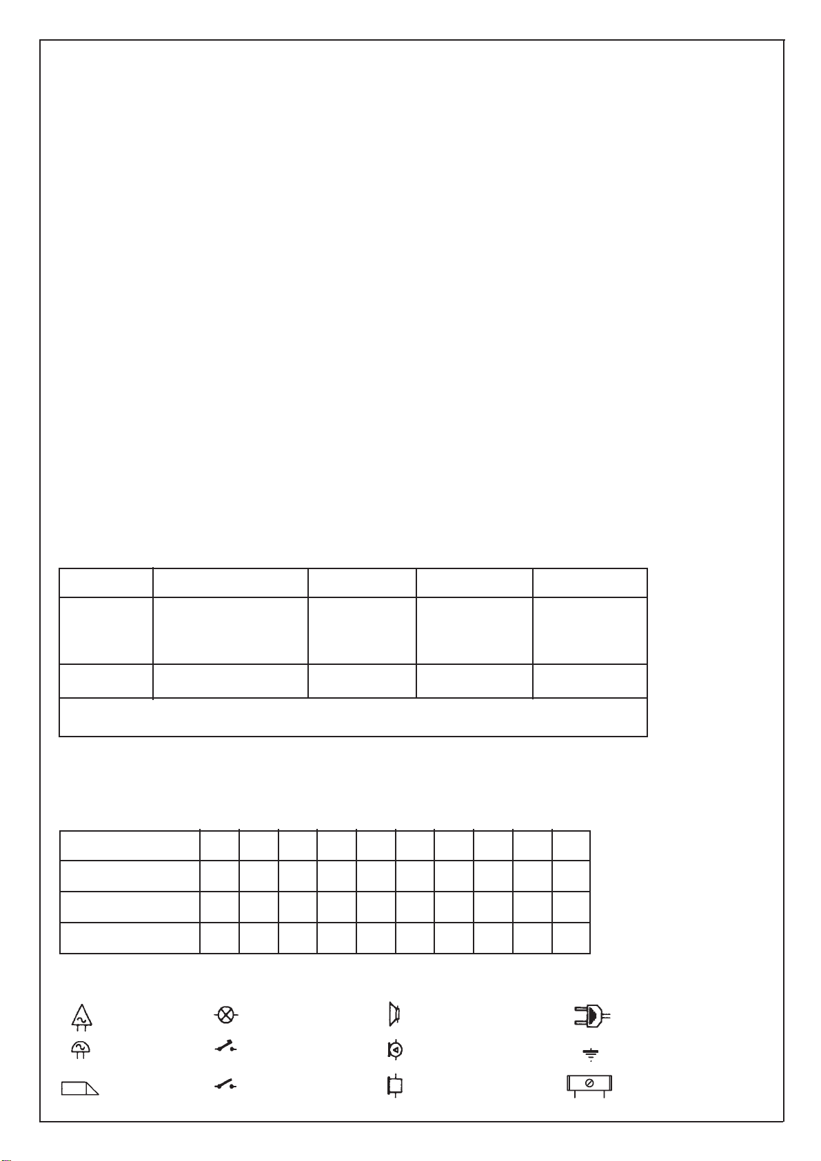
Coaxial cable block
Ground
A.C. supply from mainsLoudspeaker
Amplified microphone
Receiver
Bulb
Push-button
Switch
A.C. bell
A.C. buzzer
Electric lock
SYMBOLS
GENERAL RULES FOR INSTALLATION
Wiring should be installed in separate lines from electrical
and industrial cables. The use of coloured conductors will
facilitale connections. For the camera entrance panel instal-
lation, please, note that:
A) Camera operates from -5° + 50° C; to avoid overheating,
protected it from sunlight with some form of shelter.
B) Lens must be protected against direct light (sun, car
headlights, etc.).
C) Person to be framed by camera must be illuminated from
the front. If lighting is insufficient use an additional exter-
nal lamp powered directly by the mains.
D) Before closing unit, clean protective glass and lens,
repeat this operation from time to time.
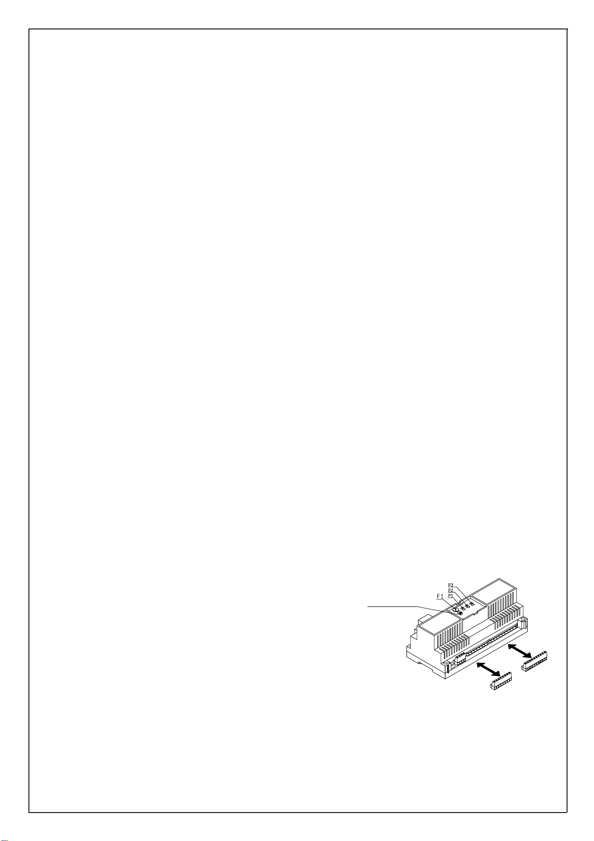
Power supply Art. 6680 must be placed in a dry place far
from sources of dust and heat. To facilitate check-ups and
adjustments, make sure that the place is easily accessible.
Fix power supply to wall with proper support and fixing
screws provided with the package or inserting it with proper
DIN module. Before connecting it, ensure that conductors
are not interrupted or short-circuited.
Installation should be made in lines separated from electric
mains. To ensure user safety, all units run on low voltage and
are separated from electric-mains by an high isolation tran-
sformer. It is advisable, in any case, to instal a thermal
magnetic switch with an adequate capacity between the sup-
plying mains and the unit. When repairing and/or servicing
the power supply it will be sufficient to loosen the screws pla-
ced on the front side to remove the front panel, after having
switched off the power.
SAFETY INSTRUCTIONS FOR INSTALLERS
- Carefully read the instructions on this leaflet: they give
important information on the safety, use and maintenance
of the installation.
- After removing the packing, check the integrity of the set.
Packing components (plastic bags, expanded polystyrene
etc.) are dangerous for children. Installation must be car-
ried out according to national safety regulations.
- Upstream of the audio or video door entry system, it is nec-
essary to install a suitable bipolar switch with distance
between contacts of at least 3mm.
- Before connecting the set, ensure that the data on the label
correspond to those of the network.
- Before cleaning or maintenance, disconnect the set.
- In the event of a fault and/or poor operation of the device,
switch off the mains power with the bipolar switch on the
audio or video door entry system and do not tamper with
the device. For repairs apply only to the technical assis-
tance centre
authorized by the manufacturer. Safety may be compro-
mised if these instructions are disregarded.
- Do not obstruct openings of ventilation/heat exit slits.
- Installers must ensure that manuals with the above instruc-
tions are left on connected units after installation, for users’
information.
- All items must only be used for the purposes designed.
Section type Terminals Ø fino a 50 m. Ø fino a 100 m. Ø fino a 200 m.
a
0, 3, 12, 15, -, +, AS, S1
C1, C2, C3, P1, P2, +T
1 mm21,5 mm22,5 mm2
lock, calls
b Other 0,75 mm21 mm21,5 mm2
Video 75 Ohm coaxial cable (type RG59) or RG11double insulation
MINIMUM CONDUCTOR SECTION FOR STANDARD VIDEO-DOOR ENTRY
SYSTEM AND TWO-CHANNEL VERSION WITH COAXIAL CABLE (in mm2)