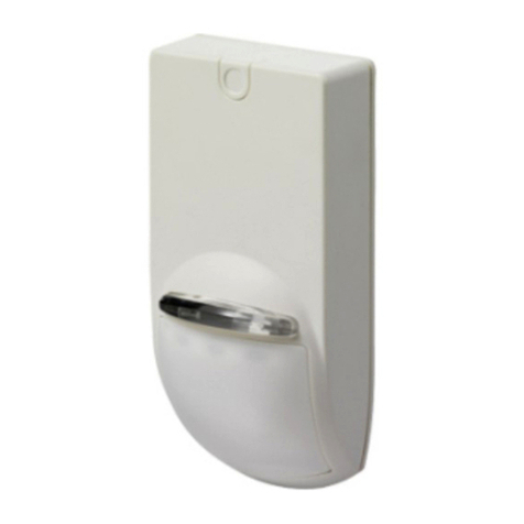
Ados TB135 Series User manual

1513-MPTB13ME Rev. 0 Pag. 1 di 12
INSTRUCTION
MANUAL
TB135x
5
4
3
2
1
0
Emission 04/11/11 G. Paulitti C. Laserra
1513.doc Rev. Subject of the revision Date Prepared Checked Approved

ADOS S.R.L. Buccinasco (MI)
1513-MPTB13ME Rev. 0 Pag. 2 di 12
INDEX
1. INTRODUCTION....................................................................................................................3
1.1 General ..................................................................................................................................3
1.2 Version/option .......................................................................................................................3
1.3 Equipment marking description .........................................................................................3
1.4 Nameplate..............................................................................................................................4
1.5 Power supply label................................................................................................................4
1.6 Technical data .......................................................................................................................4
1.7 Baud rate selection................................................................................................................5
2. REPEATER OPERATION.....................................................................................................6
2.1 Repeater power on................................................................................................................6
2.2 Display indication.................................................................................................................6
2.3 Time out.................................................................................................................................6
2.4 Receiver errors......................................................................................................................6
2.5 SERIAL INTERFACE MANAGEMENT..........................................................................7
3. INSTALLATION......................................................................................................................8
3.1 Material receiving.................................................................................................................8
3.2 Repeater mounting ...............................................................................................................8
3.3 Wiring....................................................................................................................................9
3.3.1 Power supply wiring (AC version)...................................................................................................9
3.3.2 Serial port connection.....................................................................................................................10
3.4 Zero input option................................................................................................................ 11
4. MAINTENANCE...................................................................................................................12
4.1 Preventive maintenance .....................................................................................................12
4.2 Corrective maintenance .....................................................................................................12

ADOS S.R.L. Buccinasco (MI)
1513-MPTB13ME Rev. 0 Pag. 3 di 12
1. INTRODUCTION
1.1 General
TBL13x is a numerical repeater with a digit size of 135 mm. The repeater is driven from serial line.
The repeater can be assembled with 5 red Digits.
The repeaters can be connected directly to ADOS weighing instruments (A200E, A100E, T050E,
T060E, A101E,A120E) or to other host system using the same protocol.
1.2 Version/option
T B 1 3 X X
Number of digits (5)
Power supply (2=230 VAC - 1=120 VAC
3=24 VAC – 6=48 AC)
1.3 Equipment marking description
The unit is marked with symbols compliant with European Standard 61010-1 (September 1994).
SYMBOL DESCRIPTION
Alternating current
Protective conductor terminal
Earth (ground) terminal
Caution (refer to accompanying
documents)
Caution, risk of electric shock
Keep this instruction manual for consultation by all personnel authorized to operate the instrument
for as long as the instrument remains in service.
Additional copies may be ordered fromADOS service centres.
If additional technical information or clarification is required, contact an ADOS service centre.
The operator responsible for the use of the equipment must make sure that all of the safety rules in
force in the country of its use should be applied, to guarantee that the equipment is used in
conformity with the use for which it is destined and avoid any dangerous situation for the users.

ADOS S.R.L. Buccinasco (MI)
1513-MPTB13ME Rev. 0 Pag. 4 di 12
1.4 Nameplate
Each unit contains information necessary for a correct identification, model and serial number.
These data together with the software version shall be given in case of inquiry.
It is important to provide this information when requesting information or instructions regarding the
instrument, along with the programme version, which are shown on the manual and is displayed
when the instrument is switched on.
1.5 Power supply label
Before connecting the equipment to the power source, verify that the selected value corresponds to
the voltage provided on the label side. If the selected value varies from the voltage specified in the
license plate, it is recommended not to use the equipment and to call the customer service for
voltage change.
1.6 Technical data
Power supply 230 VAC 50/60 Hz -15%...+10%
120 VAC 50/60 Hz (optional) -15%...+10%
24 VAC-48 VAC (optional) -15%...+10%
Consumption 20 VA
Fuse Thermal fuse
Operating temperature from - 10 C to + 40 C
Storage temperature from - 40 C to + 70 C
Relative humidity 95% non-condensing
Serial line RS232 or RS485 jumper selectable
Housing Painted steel frame for wall mounting
Dimension See drawings
Weight TB13 9.1 kg
Mounting Wall mounting

ADOS S.R.L. Buccinasco (MI)
1513-MPTB13ME Rev. 0 Pag. 5 di 12
1.7 Baud rate selection
To configure the speed of the serial line open the case unscrewing the eight external screws, turn
down the top part of the case.
The programming operation is performed by the four keys places on the CPU board.
ENT DEC
ESC INC
to access baud rate configuration press ENT
C
ON
F
press ENT again to access the configuration parameter or press ESC to cancel
B
A
UD
the name of parameter will appear on the display
once the required parameter has been identified, modification can be made by pressing ENT
B
A
UD
9
6
0
0
the parameter value will appear on the display and the name of the parameter will flash
intermittently
use the INC and DEC keys to change the parameter value (press the key for more than 3
seconds to activate the automatic repetition option)
press ENT to confirm the set value or press ESC to cancel

ADOS S.R.L. Buccinasco (MI)
1513-MPTB13ME Rev. 0 Pag. 6 di 12
DON
E
If this word appears it means that the setting has been successful.
The configuration parameter available is as follow:
BAUD velocità di trasmissione (baud rate)
(1200 – 2400 – 4800 – 9600)
2. REPEATER OPERATION
2.1 Repeater power on
When powered on the instrument displays the following sequence of indications, at intervals of
about two seconds:
A
DO
S
RI
P
N
R1.
0
0
(Software version)
B
9
6
0
0
(Baud rate)
2.2 Display indication
2.3 Time out
A two second receiver time out is provided in the repeater: the timer is reloaded each time a new
character is received. When the timer expires the following message will be displayed:
LIN
E
(flashing)
2.4 Receiver errors
If the repeater receives no valid messages in two second time (so if some messages are received but
containing erroneous data): the following message will be displayed:
C
H
A
R(flashing)

ADOS S.R.L. Buccinasco (MI)
1513-MPTB13ME Rev. 0 Pag. 7 di 12
2.5 SERIAL INTERFACE MANAGEMENT
The serial line is available in both the RS232 and RS485 mode. Selection is made by means of a
jumper on CPU.
Operating parameter of the serial line are:
8 bit - No Parity - 1 Stop
4
RTX485- B
RTX485-A
SGND
3
2
1
RS232
RS485
RX232
TX232
5

ADOS S.R.L. Buccinasco (MI)
1513-MPTB13ME Rev. 0 Pag. 8 di 12
3. INSTALLATION
3.1 Material receiving
Remove the instrument from its packing and check if it has been damaged during transport.
Claims for any damage must be submitted immediately and in writing to the supplier and to the
carrier which delivered the goods.
The instrument should be delivered with the following :
1 copy of the instruction manual
2 copies of the instrument test certificate (check that the serial no. reported on instrument label
corresponds to what is reported on the test certificate)
2 cable mounting kits
4 mounting brackets
3.2 Repeater mounting
Repeater can be mounted by means of brackets or using the holes in the back panel.
A 500
B 260
C 280
P 305
H 85
L 605

ADOS S.R.L. Buccinasco (MI)
1513-MPTB13ME Rev. 0 Pag. 9 di 12
3.3 Wiring
All connection to the repeater are made using two Harting connectors.
WARNING
Any wiring must be done when the instrument is powered off
Check carefully the value of the power supply and the power supply wiring
ANY CONNECTION ERROR VOIDS WARRANTY
The connection to the safety ground must always be done.
For serial line wiring shielded cable is recommended.
Serial line wiring must be separated from power lines
3.3.1 Power supply wiring (AC version)
CONNECTOR PIN FUNCTION
LINE EARTH
LINE 1 Line 230 VAC/120/VAC/24 VAC/48VAC
LINE 2 Line 230 VAC/120/VAC/24 VAC/48VAC
Connect pin to the plant protective earthing system.
UNLESS OTHERWISE INDICATED, THE INSTRUMENT IS SUPPLIED FOR USE WITH
230 VAC POWER SUPPLY

ADOS S.R.L. Buccinasco (MI)
1513-MPTB13ME Rev. 0 Pag. 10 di 12
3.3.2 Serial port connection
Connections must be done with a shielded cable (RS232 lines) or with a twisted pair shielded cable
(RS 485 lines).
The cable must not be channelled with other cables (i.e. outputs connected to remote switches or
power supply wires), but must follow its own route.
The serial connection wire must be a maximum of 15 metres long (EIA RS-232-C standards) or
1000 metres in case of RS485.
RS232
In order to create the serial connection use a shielded cable, making sure that only one of the two
shield ends is grounded. If the cable has more conductors than those used, connect the free
conductors to the shield.
RS485
In the RS485 modality, put a 50 resistor in parallel (where necessary) to the signal of the unit that
is farthest from the HOST to correct for possible signal reflections.
CONNECTOR PIN FUNCTION
DATA 1 RS232 - RX
DATA 2 SIGNAL GROUND
DATA 3 RS485 - A
DATA 4 RS485 - B

ADOS S.R.L. Buccinasco (MI)
1513-MPTB13ME Rev. 0 Pag. 11 di 12
3.4 Zero input option
In the TB135x-I version the repeater provides for the possibility, through a contact closure, to
zeroing the reading.
The function is lost with the shutdown of the equipment.
There are not effects of loss of safety function in case of load limiting systems (zero being carried
out only locally on the repeater).
The input is active on the rising and falling edge.
The closing of contact should be made with voltage-free contact.
The connections to the data connector are modified if compared to the standard version and are
showed in the table here below.
CONNECTOR PIN FUNZIONE
DATA 1 ZERO INPUT
DATA 2 ZERO INPUT
DATA 3 RS485 - A
DATA 4 RS485 - B

ADOS S.R.L. Buccinasco (MI)
1513-MPTB13ME Rev. 0 Pag. 12 di 12
4. MAINTENANCE
4.1 Preventive maintenance
The instrument needs no particular preventive maintenance.
For safety reason is a good practice to check periodically, by visual inspection, the connections to
the protective earthling system.
4.2 Corrective maintenance
Any corrective maintenance to possible failures must be carried out at ADOS laboratories or at least
by ADOS authorized personnel
EVERY UNAUTHORIZED ACCESS TO THE INSTRUMENT VOIDS WARRANTY
Table of contents
Other Ados Security Sensor manuals
