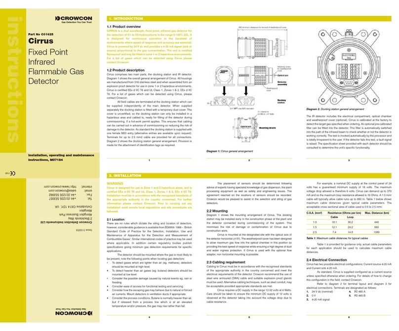
EPS IPES-IR3 User manual

IPES-IR3 Flame Detector
Operating Manual
820-0003

820-0003
IPES IR3 Flame Detector
Operating Manual
Page 2of 37
IPES-IR3 Flame Detector
Operating Manual
820-0003
ESP Safety, Inc.
555 North First Street San Jose,
CA 95112 USA 408‐886‐9746
May 2020
Revision History: 820‐0003
Date
Revision
Description
Approved
3/14/13
02
Addition; Appendix C Warranty &
Return Policy
Burgos
3/25/13
03
Reformat
Burgos
2/28/14
04
Updated Functional TestProcedure
Burgos
10/31/14
A
Update FM references; change PN from
80010‐001; steel enclosure only
ECO 141103
\
10/19/2016
B
New Terminal Board Connections
FOV Diagram. Self Test Output
Martinez
05/01/2020
C
HART Communication
Wong

820-0003
IPES IR3 Flame Detector
Operating Manual
Page 3of 37
Table of Contents5
1.0 Introduction....................................................................................................................................................................5
Introduction.................................................................................................................................................................5
Our Mission ................................................................................................................................................................5
ESP Safety, Inc. Contact Information ........................................................................................................................5
2.0 Description......................................................................................................................................................................6
Application..................................................................................................................................................................6
Specifications.............................................................................................................................................................6
3.0 Safety Considerations .....................................................................................................................................................8
Guidelines ..................................................................................................................................................................8
Explosion Protection Means.......................................................................................................................................8
4.0 FM Compliance ...............................................................................................................................................................9
IPES-IR3 ....................................................................................................................................................................9
Standards...................................................................................................................................................................9
Flame Response Sensitivity.......................................................................................................................................9
False Stimuli Exposure ............................................................................................................................................10
Field of View.............................................................................................................................................................10
5.0 PerformanceCharacteristics .........................................................................................................................................11
Appearance
...............................................................................................................................................................11
Response Time
.........................................................................................................................................................11
Generation of Alarm Signals
......................................................................................................................................11
Elimination of False Alarms
........................................................................................................................................12
Serviceability............................................................................................................................................................12
LED ..........................................................................................................................................................................12
Optical Integrity ........................................................................................................................................................12
Analog Signal ...........................................................................................................................................................14
Digital Signal ............................................................................................................................................................14
Relay Dry Contact Signal.........................................................................................................................................14
Operating Modes......................................................................................................................................................14
6.0 Installation ....................................................................................................................................................................15
Component Parts and Delivery Set..........................................................................................................................15
Visual Examination...................................................................................................................................................15
Pre‐Installation Steps...............................................................................................................................................15
Installation................................................................................................................................................................15
Moisture Damage Protection....................................................................................................................................16
General Wiring Requirements..................................................................................................................................16
24VDC Requirements ..............................................................................................................................................16
Earth Grounding.......................................................................................................................................................17
Power Cable Conductor Size affects CableLength.................................................................................................17
IPES‐IR3 Terminal Block .........................................................................................................................................18
Setting the Modbus Address and Baud Rate...........................................................................................................18
Completing the Installation.......................................................................................................................................19
IPES‐IR3 3 Wire +4 to 20 mA Current Loop WiringDiagram ..................................................................................20
Connection to Digital RS‐485Circuit........................................................................................................................20
7.0 Startup and Operation ..................................................................................................................................................21
Installation Review Prior to Startup..........................................................................................................................21
Performance Test.....................................................................................................................................................21
Test Equipment........................................................................................................................................................21
Power‐On Self‐Test..................................................................................................................................................21
IPES‐IR3 in Self‐Test Mode.....................................................................................................................................22
Fire Detection Test...................................................................................................................................................22
Photonic Detector Locations....................................................................................................................................23
Dust/ Obstruction Fault Test ....................................................................................................................................23

820-0003
IPES IR3 Flame Detector
Operating Manual
Page 4of 37
8.0 Troubleshooting............................................................................................................................................................24
Troubleshooting Table .............................................................................................................................................24
9.0 Maintenance.................................................................................................................................................................25
Maintenance Activities .............................................................................................................................................25
Daily Maintenance....................................................................................................................................................25
Every Six Months .....................................................................................................................................................25
Automatic Testing ....................................................................................................................................................26
10.0 Transportation and Storage ........................................................................................................................................26
11.0 Warranties ..................................................................................................................................................................27
12.0 Repair and Return .......................................................................................................................................................28
Field Repair..............................................................................................................................................................28
Return Material Authorization (RMA) Number.........................................................................................................28
13.0 Parts Ordering Information.........................................................................................................................................28
14.0 Certifications...............................................................................................................................................................29
Appendix A: IPES-IR3 Explosion Protection Means.............................................................................................................31
Appendix B: IPES Digital Communications Protocol ...........................................................................................................32
Appendix C: HART Communication Protocol......................................................................................................................34
It is important that this entire manual be thoroughly read and
understood prior to installing or operating the IPES‐IR3. Any
deviation from the recommendations in this manual may impair
system performance and compromise safety.

820-0003
IPES IR3 Flame Detector
Operating Manual
Page 5of 37
1.0 Introduction
Introduction
The IPES‐IR3 flame detector’s advanced microprocessor based technology ensures rapid flame recognition and alarm
signaling. In addition, the IPES‐IR3’s selective, multiple spectrum technology virtually eliminates false alarms from a
variety of sources including:
●Direct or indirect sunlight
●Arc welder flash, resistive heaters
●Fluorescent, halogen
●Incandescent light
●Nuclear radiation
The IPES‐IR3 generates an alarm signal only when detection from three different IR wavelengths agree that a flame or
fire is present in the field of view. Upon confirmation of flame or fire, the IPES‐IR3 triggers alarm relays and provides
alarm signals via RS‐485 Modbus and industry standard +4 to 20mA current loop to the users’ receiving devices and
alarm systems.
For ease of operation status and alarm condition the IPES‐IR3 provides an easily visible high illumination Tri State LED
that follows an Industry Standard protocol:
●Green for normal operation
●Yellow for fault condition
●Red for alarm Conditions
The IPES‐IR3 provides superior false alarm processing making it the detector of choice. Alarms occur instantly after our
proprietary False‐Positive Algorithm determines possible alarm states. This makes IPES‐IR3 the industry standard for
several industrial applications:
Our Mission
ESP Safety, Inc.’s mission is to provide complete turn‐key protection solutions beginning with the design stage, through
system installation and commissioning, and on‐going field service in hazardous environments. Our line of
industry‐leading products, services, and systems benefits society, saves lives, and preserves capital resources.
ESP Safety, Inc.
Contact Information
Telephone: 408‐886‐9746
FAX: 408‐886‐9757
Address: 555 North First Street, San Jose, CA 95112 USA

820-0003
IPES IR3 Flame Detector
Operating Manual
Page 6of 37
2.0 Description
Application
The IPES‐IR3 design and explosion‐proof ratings make it an excellent choice for indoor and outdoor applications,
including:
Drilling andproduction
Paintproduction
Automated and manned ocean
Power Plants‐ Nuclear, Coal, Oil,
based platforms.
Natural Gas, Solar Process, MHD
Fuel loading and transfer facilities
Shipping Tankers,Freighters.
Refineries
Virtually any vessels that may
havea
Bulk terminals
potential firehazard.
Tank farms and storage facilities
Laboratory and Plasma
LNG/LPG processing and storage
Study/Process
Compressor stations
Transportation facilities,Airports,
Pipelines and pump stations
Petrochemical processing
facilities
Subways, Aircraft hangers
Oil and Gas Boilers
Fertilizerproduction
Stage and entertainment
special effects
Specifications
The IPES‐IR3 meets industry certifications and requirements for Hazardous Locations.
Detection Type: Optical
Detection Method: Multiple Spectrum Infrared Radiation Source Spectral Range: Three points in a range of 4.0 to 5.0 m
Detection Process Time:
4.5 to 7 Seconds
(Complies with FM Standard 3260)
Refer to Section 4.0
Detection Distance: Minimum 211 feet (64meters) depending on detected fuel.
Detection Cone of Vision: Up to 90° (45° Left/Right of center)
Sensitivity: User Selectable for distance and False/Positive process time
Power requirements: 24VDC nominal (18‐32VDC range)
Power Consumption: 3 VA (3 Watt) Max
Outputs:
●Industry Standard +4 to 20mA
●1 Alarm Relays (SPDT/Form‐C latching)
●1 Fault condition (NO/Form‐A)
*All Relays Contact Rating 1 Amp@125VAC/30VDC
●Digital RS‐485 Modbus
●HART Communication Protocol
Cable Distance: 6200ft (1900m) 18 AWG
Ingress Protection: IP66
Vibration: Meets FM 3260: 2000
Impact Resistance: 1.9 Joules
Test Method: ITES Test Lamp
RFI‐resistant to interference by EMI and RFI: EMC Directive compliant with CE mark. Not susceptible to keying 5 watt
walkie‐talkie at distances greater than 1 foot.

820-0003
IPES IR3 Flame Detector
Operating Manual
Page 7of 37
Optical Integrity: IPES‐IR3 performs an automatic calibrated performance test once per minute to verify complete
detector operation capabilities.
Operating Temperature: ‐40°F to +185°F (‐40°C to 85°C)
Storage Temperature: ‐76°F to +185°F (‐60°C to 85°C)
Humidity Range: 0 to 95% relative humidity
(can withstand 100% condensing humidity for short periods of time)
Conduit Entry: ¾” NPT
Enclosure Material: Stainless Steel Grade 316
Weight: Stainless Steel 11lbs (5.0kg)

820-0003
IPES IR3 Flame Detector
Operating Manual
Page 8of 37
3.0 Safety Considerations
Guidelines
For maximum safety:
•Only persons who have thoroughly read and understood this manual, are trained in safety techniques, and have
electric-safety certificates are permitted to install and operate the IPES-IR3.
•Never operate the IPES-IR3 if the casing is damaged.
•Do not open, separate or disassemble the IPES-IR3 when energized.
•Refer to the Appendices and diagrams in this manual to ensure that the wiring is in compliance with local
ordinances and the NEC.
•Perform regular testing and maintenance as outlined in the Maintenance section.
•Ensure that fire-alarm and fire-extinguishing systems and controls are switched off before any testing or
maintenance to avoid unwanted operation of alarms and fire-extinguishing equipment.
Also see the individual sections in this manual for relevant specific safety guidelines.
Explosion Protection
Means
The table below describes design features that protect the IPES-IR3 against explosions:
Feature
Protection Means
Enclosure of
Current Carrying
Parts
The casing includes spigot joints with controlled gaps
to meet explosion‐proof requirements for installation
in Class I, Division I, Group B, C and D, and T4 locations.
Case Mechanical Strength
The high mechanical strength of the case is able to
withstand high explosive pressures without rupture or
failures of mechanical parts. The case design is in
accordance with FM 3600 and FM3615.
Manufacturing Control
Of Casing
Important parametersinclude:
●
Maximum width and minimum length of spigot joints
●
Surface roughness of the joinedparts
●
The number of complete intact threads at the
conduit entry point
Ignition Temperature
The ignition temperature of the surrounding
environment is limited by the outside surface
temperature of the housing, which does not exceed
275°F (135°C).
Securing of Bolts,
Joints and Grounding
Spring washers, lock washers, and lock nuts maintain the
integrity of the bolted connections by preventing
loosening of the bolts.
Joined Parts Protection
Anti‐seize lubricant is applied on the critical joints as
described on Appendix A.
Casing Ingress Protection
The design of the casing is protection class IP 66 in
accordance with IEC 60529‐004.
Sealing Cables at
Conduit Entry
Use approved hazardous location sealed conduit fittings.
Foroutdoor installations, ensure sealing meets IP66
requirements.
Before installing and operating the IPES‐IR3, be sure to read this
entire manual. Failure to follow these guidelines could result in
impaired product performance and safety hazards.

820-0003
IPES IR3 Flame Detector
Operating Manual
Page 9of 37
4.0 FM Compliance
IPES-IR3
Meets FM (US and Canada) certifications and requirements for Hazardous Location classification: Class I, Division I,
Group B, C and D and T4 Case design accords with FM 3600 and FM 3615. Ta = ‐40°C to +85°C (‐40°F to +185°F) IP66
Standards
TITLE
AUTHOR‐NUMBER
DATE
National Fire Alarm Code
ANSI/NFPA 72
2002
Radiant Energy‐Sensing Fire
Detectors for Automatic Fire
Alarm Signaling
ANSI/FM –3260
2004
Radiant Energy‐Sensing Fire
Detectors for Automatic Fire
Alarm Signaling
FM Approvals ‐ 3260
2000
Electrical Equipment For Use In
Hazardous (Classified) Locations–
General Requirements
FM Approvals –3600
1998
Explosion proofElectrical
Equipment –General
Requirements
FM Approvals –3615
2006
Flame Detectors
ULC/ORD ‐ C386
1990
Standard for Smoke Detectorsfor
Fire Alarm Systems
CAN/ULC ‐ S529
2002
Threaded Conduit Entries
CSA C22.2 No. 0.5
1982
(Reaffirmed)
(1999)
Explosion‐Proof Enclosuresfor
CSA C22.2 No. 30
1986
Use in Class I Hazardous Locations
(Reaffirmed)
(2003)
Degrees of Protection Provided by
ANSI/IEC 60529
2004
Enclosures (IP Code)
CSA‐C22.2 No. 60529
2005
Explosive Atmospheres, General
Requirements
ANSI/ISA 60079‐0
2009
Explosive Atmospheres,
Equipment protection by
flameproof “d” enclosures
ANSI/ISA 60079‐1
2009
Flame Response
Sensitivity
When an IPES‐IR3 detector is exposed to a series of test fires along the center line of the sensor as described in the table
below, the alarm response of the IPES‐IR3 is below the 30‐ second response time required under FM Standard 3260.
Fuel
Distance
Fire Size
Average Time
n‐Heptane
211 ft. (64 m.)
1 ft. x 1 ft. (32.5 cm.) pan
9 sec.
Denatured ethyl
alcohol (85.4%)
151 ft. (46 m.)
1 ft. x 1 ft. (32.5 cm.)
11 sec.
JP4
206 ft. (63 m.)
2 ft. x 2 ft. (60 cm.) pan
10 sec.

820-0003
IPES IR3 Flame Detector
Operating Manual
Page 10 of 37
False Stimuli
Exposure
When the IPES‐IR3 is exposed to the fires specified above, and are in the presence of the following false stimuli sources –
modulated at approximately 1.5 Hz, and un‐modulated – no false alarm activation or instability occurs at the minimum
distances listed below.
Source
Distance
1.5 kW Heater
36 inches (0.9 m)
Arc welder, 200A, 3/16” – 7018
electrode
9.0 feet (3.7 m)
Fluorescent, (2) 20W (6000 Lux)
0 inches (0 m)
Halogen, 500W
36 inches (0.9 m)
Incandescent, 100W (2000 Lux)
12 inches (0.3 m)
Direct sunlight
Detectors not affected by frequency
range of visible light
Indirect sunlight
Detectors not affected by frequency
range of visible light
Field of View
The IPES‐IR3 has a 90° cone of vision (horizontal) with the highest sensitivity lying along the central axis
X= Distance in Ft Y= Angle of Vision
Refer to Section 7.0 for testing method

820-0003
IPES IR3 Flame Detector
Operating Manual
Page 11 of 37
5.0 PerformanceCharacteristics
Figure 5-1: IPES-IR3 Components
Appearance
The IPES‐IR3 consists of an explosion‐proof casing with sensors to detect electromagnetic radiation from flames at three points
within a spectral window of 4.0 to 5.0μm. Detection is performed using Infrared Sensors that capture heat and radiating gas
signatures emitted by fire. Significantly, the IPES‐IR3 can detect fires fueled by hydrocarbon‐based liquids and gases that may
not be visible to the human eye.
The basic technology is well tested and used for many devices designed for human interaction. These include night vision
equipment, FLIR navigation assist, and Spectral Telescopes used in astronomy.
The IPES‐IR3 uses microprocessors with proprietary algorithms that transform the detected signal into industry standard analog
and digital communication signals, alarms indicators.
Response Time
The IPES‐IR3 response time detecting radiation emitted by test sources of n‐Heptane combustion in a 12” x 12” (0.3m by
0.3m) pan, and ethyl alcohol combustion in a 12” x 12” (0.3m by 0.3m) pan, at a distance of 150 feet (46 meters) does not
exceed 30 seconds.
The sensitivity and response time can be varied in order to reduce unwanted “noise” when the IPES‐IR3 identifies a fire, or
the distance to the probable place of fire is short (“near/far” and “slow/fast” modes).
Generation of Alarm
Signals
The IPES‐IR3 takes the following parameters into consideration when generating an alarm signal:
•
Magnitude of signals from different optical channels
•
Ratios between the signal amplitudes of different channels
•
Signal modulation frequency
•
Phase relationships among the channels

820-0003
IPES IR3 Flame Detector
Operating Manual
Page 12 of 37
Elimination of False
Alarms
False alarms from detectors used for industrial applications can cost productivity in down time. This is especially noted for
automated systems and processes.
Conversely, failure to generate an alarm can have catastrophic results.
The combination of microprocessor, algorithms, multiple sensors and wavelength range settings makes the IPES‐IR3 an
excellent choice for elimination of false positive indicators caused by non‐flame sources of radiation such as artificial
lighting, direct and indirect sunlight, lightning, electrical arcs, radiation (nuclear), arc welding and metal grinding.
An Alarm condition will normally override a Fault condition unless a loss of operating power impairs the detector’s ability to
generate or maintain an alarm. The IPES‐IR3 reports both Fault and Alarm conditions exclusive of each other. This means
both a Fire and Fault can be reported at the same time if they occur simultaneously.
Serviceability
The IPES‐IR3 remains serviceable in non‐heated rooms or under sheds at temperatures from –40°F to +185°F (–40° to
+85°C).
LED
Normal, Fire and Fault conditions are indicated by status LEDs located on the cover. Refer to
Table 5‐1: Determining
LED Conditions.
Optical Integrity
To maintain reliability of the IPES‐IR3, the optical devices are automatically self‐tested for
radiation transmission
every 25 to 45 minutes. This routine test does not require the use of a test lamp. This test determines whether any
dust or other contamination has formed on the detecting windows which would scatter the infrared radiation.

820-0003
IPES IR3 Flame Detector
Operating Manual
Page 13 of 37
Table 5‐1: Determining LED Conditions
After completing all installation steps, refer to the illustration and LED indicator table below to determine LED conditions.
State
IPES‐IR3 status
Fire
Relay State
Fault
Relay Status
Output
signal,
am
Normally open
when energized
Normally closed
when energized
LED Status Condition
1
No power
supply voltage
Open
Open
0mA
Off
2
After switching
on during 45
sec.
Open
Open
2mA
Continuous green LED light for the first
10 sec. and then the green LED will begin
flashing.
3
Fault or optical
interference
(dust)
Open
Open
2mA
Alternate flashing of the yellow and
green LED lights.
4
Normal
(no faults or
fires during
operation)
Open
Closed
4mA
Continuous lighting of the green LED
light.
5
Fire
Closed
Closed
18mA
Continuous lighting of the red LED light.
6
Fire & Fault
Closed
Open
8mA
Alternate flashing of the yellow and
green LED light.
7
Test mode
(magnetic collar
is on)
Open
Open
2mA
Magnetic collar is on. fire relay isblocked.

820-0003
IPES IR3 Flame Detector
Operating Manual
Page 14 of 37
Analog Signal
Analog signal (4‐20 mA)
Signal level
Detector State
(±0.1) mA
Circuit opening
(2 ± 0.1) mA
Fault
(4 ± 0.1) mA
Normal
(18 ± 0.1) mA
Fire
(2 ± 0.1) mA
Magnetic Collar Test
(4.1 ± 0.1) mA
Self-Test-Every 35 minutes
Digital Signal
Informational digital signals are standard RS‐485 communication with Modbus:
●Hardware self‐test Fault
●Optical interference Fault
●Fire detected
(The digital channel protocol Modbus RTU is described in Appendix B.)
Relay Dry Contact
Signal
Relay dry contact signal:
•Operation of the normally open Fire relay dry contacts*
oFIRE relay –two‐directional single‐pole contact, which allows the state to be changed at the output to normally
closed or normally open. Relay state is set at the factory. Default setting is Normally Open (Closes when in Fire
Alarm mode). The contact relay is rated for currents ranging from 10 mA to 5 A at DC voltage of 30 V.
The output signal “Fire” can be cleared after eliminating the source of the alarm signal.
* A normally closed condition of the Fire relay contacts does not comply with the requirements of NFPA 72 or
ULC/ORD –C386 and is not approved by FM approvals.
•Operation of the normally open Fault relay dry contacts
oFAULT relay –single‐direction pole contact which is normally open. The relay is designed to handle currents of
10 mA to 5 A at DC voltage of 30 V.
Refer to Table 5‐1: Determining LED Conditions above.
Operating Modes
Possible detector configurations using ESP Commander
The IPES–IR3 has the following detector operating modes:
•“Near/far” and “slow/fast” modes – To provide maximum sensitivity.
•“Latching/non‐latching mode”– To select either latching or non‐latching functionality of the fire relay, which
provides latching alarm state for the fire‐alarm relay in compliance with NFPA 72 and ULC/ORD – C386.
The manufacturer’s default settings correspond to far and fast. To change the manufacturer’s settings, connect the
flame detector to the computer and use the ESP Commander program.
HART Protocol
Communication
The HART communication is used to monitor status of the flame detectors and provides the flexibility to make
configuration changes in the field. The important status monitored are the process value (value to determine fault, or
alarm conditions). In addition, the user can test the built-in test, which occurs automatically every 35 mins. For more
details, HART menu tree and connection diagram, please refer to the Appendix C.

820-0003
IPES IR3 Flame Detector
Operating Manual
Page 15 of 37
6.0 Installation
Component Parts
and Delivery Set
The IPES‐IR3 detector component parts and delivery set consists of the following:
•One IPES‐IR3 Fire Detector
•One Adjustable Mounting Bracket
•One Operating Manual
•IPES Mounting Hardware (bolts, nuts, washers, etc.).
•One Sunshade Hood
•Optional magnetic collar (delivered only by special request).
Compare the contents of the set to the packing list to be sure all items were received. If any items are missing, contact
ESP Safety Inc.
Visual Examination
•The nameplates and warning labels are in place.
•The external surfaces of the elements and joined surfaces of the casing are free of dents or damage.
•The tamper‐proof screw is intact on the front cover
Pre‐Installation
Steps
Make sure all removable parts are joined to the casing as tightly as possible.
Installation
Positioning the Detector
1. Position the detector to provide an unobstructed view of the area to be protected. The detector’s 90° viewing angle
is most sensitive along the central axis; therefore, position the central axis so that it has the best unobstructed view
of the place of probable fire. Use line of sight or laser level for more precise targeting.
2. Identify all high-risk fire sources, to determine the number of detectors needed for adequate coverage.
3. Locate the detector(s) for ease of cleaning and servicing. Ensure that probable fire sources are within the
detector(s) field of view and detection range.
4. When installing multiple detectors in the same area, be aware of overlapping fields of view and detector hierarchy.
Overlapping fields of view can be used to provide additional protection against false positives or false negatives,
depending on the control system logic connected to the detectors.
Note: To mitigate false positives, position the detector so that its field of view does not cover any areas outside the
hazardous area.
5. Mount the detector on a rigid surface which minimizes vibrations. Use the mounting hardware provided along with
the rubber bushings to further isolate the detector from vibrations
Note: ESP Safety Inc. recommends bolting the mounting base plate to the mounting surface. If bolting is not
possible, the mounting plate can be welded to the mounting surface if it is a similar metal (either 316 Stainless Steel
or 6061 aluminum). Before welding, be sure to remove the detector from the base plate before attempting any
weld operation.
Warning: Do not open, separate or disassemble casing when
energized! Separating the casing can result in serious damageto
the detector which could go undetected, resulting in failure to
detect fires.

820-0003
IPES IR3 Flame Detector
Operating Manual
Page 16 of 37
Moisture Damage Protection
•It is the responsibility of the installer to take proper precautions during installation to protect the
electrical connections and components frommoisture.
•Anti‐seize lubricant is provided for easy assembly and corrosion protection of the joints between the
enclosure/cover and enclosure/base. After disassembly, wipe these surfaces clean with a soft cotton
or wool cloth and then re‐apply a thin layer of lubricant prior to assembly.
•If installing wiring cable in conduit, do not use conduit for wiring to other equipment.
•Care should be taken to not install the detector where heavy condensate, rain, or fog can cover the
lens and reduce the sensitivity of thedetector.
General Wiring Requirements
Cabling Guidelines
If installing connection cables in an explosion proof conduit, do not use the same conduit tocarry wiring for
any other purpose or equipment.
Minimum 14 AWG (2.08 mm2) shielded cable conductors are required for optimal performance. The gauge of the
wire used determines the maximum distance between the 24VDC power sources.
When using Modbus, power and signal must be separate shielded twisted pair conductors
24VDC Requirements
The IPES‐IR3 detector has a maximum power draw of 3VA/Watt in an active alarm state with all relays and optics
heater active. (Fault, Alarm1) Select a power supply with adequate capability for the calculated load. Ensure that
the 24VDC (+/‐8VDC) power positive and common connections are from the same source
Warning: System ground must be provided at the point of
origination for 24VDC. Failure to do this may result in loss of range
and/or signal integrity.
Avoid low frequency, high voltage, and non‐signaling conductors to
prevent potential EMI problems.
Caution: All cable/conduit entries must be sealed with an
appropriate and certified sealing plug and cable gland. The use of
industrial grade, armored field cable is recommended.

820-0003
IPES IR3 Flame Detector
Operating Manual
Page 17 of 37
Earth Grounding
The enclosure of the IPES‐IR3 must be earthed/grounded for electrical safety and to limit the effects of radio
frequency interference. An earth/ground point is provided on the outside of the IPES‐IR3 Explosion Proof
enclosure.
Use 14 AWG copper (Stranded, or Solid),wire.
Loosen the nut sufficiently to enable wrapping of the wire or wire terminated with a crimped lug around the
thread in a “U” shape. Raise the flat and lock washers and position the wire between the 2 flat washers and
ground base.
*Note: Earth and System Grounds are separated to prevent ground loop potential plus maintain signal and
current output integrity
Power Cable Conductor Size affects CableLength
The IPES‐IR3 detector must receive a nominal voltage of 24 VDC (+/‐ 8VDC) to operateproperly. Wire size
requirements are dependent upon power supply voltage and wire length.
There are several possible methods to electrically connect an IPES‐IR3 that are determined by each user’s
application.
These can run from a single IPES‐IR3 running on 24VDC that is operating as an isolated device and is connected
directly to a warning system of alarms and/or lights to a network of devices that are connected in series that can
provide any mix of RS‐485 Modbus, +4 to 20 am, and relays to separate devices.
22 AWG 0.326mm2)
40.5Ω
750
2460
20 AWG 0.518mm2)
40.8
1200
3936
18 AWG 0.823mm2)
40.7Ω
1900
6232
16 AWG (1.31mm2)
40.2Ω
3000
9840

820-0003
IPES IR3 Flame Detector
Operating Manual
Page 18 of 37
IPES‐IR3 Terminal Block
Table 6‐1: Arrangement of Electrical Connections
Terminal Block
Pin
Function
X3
+24V
24VDC from system power source (External User Provided)
GND
System Ground from system power source (External User Provided)
+4/20
Industry Standard +4-20mA current loop output
RS485A
RS-485 MODBUS
RS485B
RS-485 MODBUS
R_WORK
R_WORK
Fault / Obstruction Relay Normally Closed (NC Type B) When Energized
X4
+24V
Output to next device if required
GND
Output to next device if required
-4/20
Industry Standard +4-20mA current loop output
RS485A
Output to next device if required
RS485B
Output to next device if required
R_FIRE
R_FIRE
Alarm Relay Normally Open (NO Type A) When Energized
X5
Factory Use
X6
Factory Use
Arrangement of
Electrical Connections
Arrange the electrical connections as described in Table 6‐1, Table 6‐2 and Figure 6‐3below.
To connect the IPES‐IR3 to external devices, use armored control cables 4 x 1.5, which are used in
all classes of explosive zones including indoor and outdoor sites, channels, tunnels, ground
(trenches) with corrosive medium, and in zones containing roamingcurrents.
Setting the Modbus
Address and Baud Rate
To ensure proper communications, a unique address must be assigned to each device, as duplicate
addresses are not automatically detected. Modules with duplicate addresses will report with the
same address, confusing latest updates. Record all addresses and device types after completing the
installation.
Refer to Appendix B for setting the Modbus address and baud rate.
When using an RS‐485 bus connection, it is advisable to connect the IPES‐IR3 to the bus via the
terminal box. To connect the detector to the terminal box, use a cable not longer than
1.64
feet (0.5 m). The cable characteristics should meet the requirement of the cable entries
mounted on the IPES‐IR3 casing and those of the terminalbox.

820-0003
IPES IR3 Flame Detector
Operating Manual
Page 19 of 37
Completing the Installation For the following,
1. Unscrew the M5 Socket Head Cap screws from the base. Remove the detector from the
base.
2. Detach NPT conduit bushing from base.
3. Install the base on a suitable work platform and secure using the 4 mounting screws,
washers, nuts, and rubber grommets.
4. Run the power, control, and ground wires from the conduit into the conduit bushing and
connect to the wiring terminals in the base. Follow Figure 6‐2, Arrangement and Functions
of Mounting Connection Terminals, for details.
5. Tighten the conduit bushing to 4‐1/2 +‐ 1 turns of engagement. Seal the conduit entry
with an approved hazardous location conduitsealant.
6. Run the earth ground wire to the external ground stud on thebase.
7. After completing all wiring, refer to Table 6‐1 to verify the functionality of the front cover
LEDs.
8. Inspect base and re‐apply a thin film of anti‐seize compound if required; re‐install the
detector on the base and evenly tighten the M5 screws to40 in‐lbs.
9. Upon completing the installation, check the resistance of the earth ground lug to ground
which should not exceed 1 ohm.
10. Arrange the power‐supply system so that the power‐supply voltage across the device
terminals ranges from 18 to 32 V (taking into account the IPES‐IR3 consumption).

820-0003
IPES IR3 Flame Detector
Operating Manual
Page 20 of 37
IPES‐IR3 3 Wire +4 to 20 mA Current Loop WiringDiagram
When using the current loop method of connection the circuit is a point‐ to‐point
connection between a single IPES‐IR3 and a threshold detection device. In most cases the
threshold device will provide the 24VDC power and will operate in a closed loop. Refer to
Appendix C for interpretation of
+4 to 20ma indications.
If 24VDC is from a common source, use of a connection bus‐block is recommended
to provide connect/disconnect capability without disruption to any other devices
using the same powersource.
Figure 6-3: IPES-IR3 Connection to Analog +4 to 20 mA Current Loop
Connection to Digital RS‐485Circuit
Figure 6-4: IPES-IR3 Connection to Digital RS-485 Circuit
Table of contents
