Ados GTR 210 User manual
ADOS®GTR 210
A D O S GmbH
Instrumentation and Control
Trierer Str. 23-25 @ 52078 Aachen @ FRG
T E L . : +49(0) 241 9769- 0
F A X : +49(0) 241 9769-16
E-Mail : [email protected]
Internet : http://www.ados.de
Est.
1900
Operating Manual
Gas Transmitter 210
Issue: 09/16 Rev.: 1.16

ADOS GmbH GTR 210 Rev 1.16 Page I
Contents
Page
1. Introduction ............................................................... 1
2. Conformity ............................................................... 2
2.1. MED option ......................................................... 3
3. Method of Operation ........................................................ 3
4. Installation & Operational Startup .............................................. 4
4.1 Installation.......................................................... 4
4.1.1 Electrical connection GTR 210 Standard and EX GTR 210 .............. 5
4.1.2 Electrical connection GTR 210 Comfort ............................. 6
4.1.3 Installation of the Flow Adapter .................................... 7
4.1.4 Electrical connection GTR 210 Comfort with Controlbox: ................ 9
4.2 Notes on Safe Use of the Gas Transmitter ................................ 11
4.3 Commissioning ..................................................... 12
5. Operation ............................................................... 13
5.1 Device Display ..................................................... 13
5.2 Keyboard .......................................................... 14
5.3 Alarms............................................................ 15
5.4 Trend Graph ....................................................... 16
5.5 Output Signals ..................................................... 17
5.6 Systemstart ........................................................ 18
5.7 Exception-state: sensor-overload ....................................... 19
5.8 Exception-states .................................................... 20
6. Parameterization of the Gas Transmitter ....................................... 21
6.1 Main Menu ........................................................ 22
6.1.1 Menu Item Relay .............................................. 23
6.1.2 Menu Item Time/Date .......................................... 23
6.1.3 Menu Item Language .......................................... 23
6.2 Sub-menu System .................................................. 24

ADOS GmbH GTR 210 Rev 1.16 Page II
6.2.1 Menu Item System Information ................................... 24
6.2.2 Sub-menu Hardware Test ....................................... 24
6.2.2.1 Relays .......................................... 25
6.2.2.2 Current output .................................... 25
6.2.2.3 Reset-Acknowledgement ............................ 25
6.2.2.4 Watchdog ....................................... 26
6.2.2.5 Keypad.......................................... 26
6.2.2.6 Display.......................................... 26
6.2.3 Show Alarms ................................................. 27
6.2.4 Show Faults ................................................. 27
6.2.5 Show Parameters ............................................. 28
6.2.6 Contrast..................................................... 28
6.2.7 Sub-menu Sensor ............................................. 28
6.3 Sub-menu Alarms ................................................... 28
6.3.1 Limit Values.................................................. 29
6.3.2 Confirmation ................................................. 30
6.3.3 Horn .......................................................30
6.4 Sub-menu Calibration ................................................ 31
6.4.1 Zero Point ................................................... 31
6.4.2 Span point ................................................... 31
6.4.3 Current 4 mA................................................. 32
6.4.4 Current 20 mA................................................ 33
6.5 List of all Parameters and their Valid Adjustment Ranges .................... 34
7. Maintenance Operations .................................................... 35
7.1 Calibration......................................................... 36
7.1.1 Check of calibration of the zero point .............................. 37
7.1.2 Check of calibration of the end value .............................. 37
7.1.3 Calibration of the Zero Point ..................................... 38
7.1.4 Calibration of the End Value ..................................... 39

ADOS GmbH GTR 210 Rev 1.16 Page III
7.1.5 Conversion of the test gas concentration using a substitute gas ......... 40
7.2 Check of the Output Signals .......................................... 43
8. Trouble-shooting .......................................................... 44
9. Dimensions .............................................................. 46
10. Technical Safety Characteristics ............................................. 49
11. Technical Data ........................................................... 53
11.1 Technical Data of the Gas Transmitter ................................... 53
11.2 Technical Data Sensors .............................................. 56
11.3 Measuring ranges with ec-type examination with regard to the measuring
function for explosion protection ................................. 58
11.4 Accessories and spare parts ........................................... 60

ADOS GmbH GTR 210 Rev 1.16 Page 1
1. Introduction
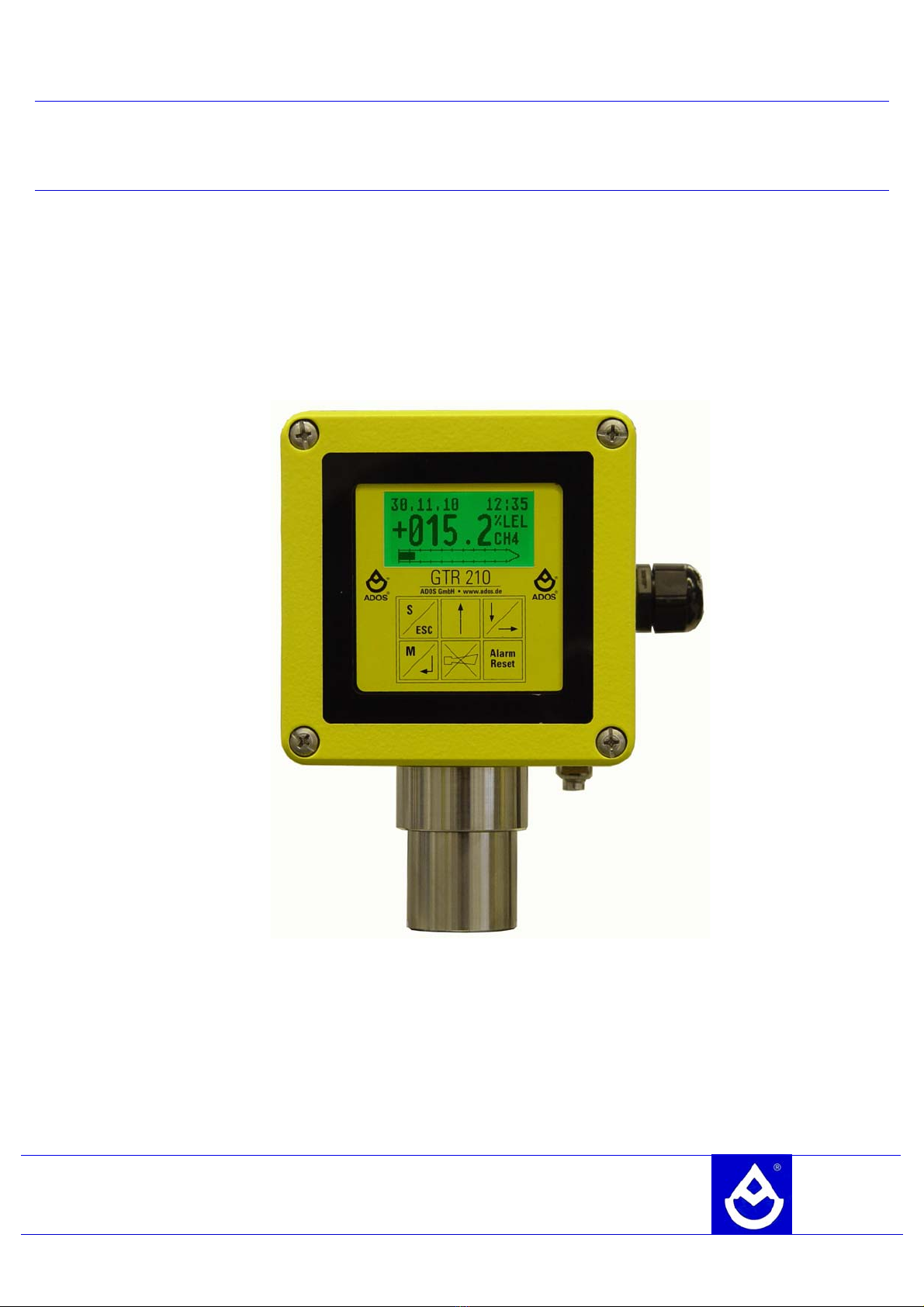
The GTR 210 is a universal gas transmitter for the detection of combustible gases, toxic gases or
oxygen. The gas transmitter can be equipped with six different types of sensing elements. It converts the
measured gas concentration to a physical concentration value. The transmitter shows the concentration
on an integrated display and transfers it via the current port to an evaluation unit.
Three versions of the transmitter are available:
1. GTR 210 Standard:
The GTR 210 Standard is the basic model of the GTR 210 family. It provides as User interface
a LCD graphic display, a touchpad with six keys and one current output.
2. GTR 210 EX:
This is the flame-proofed version of the GTR 210 Standard. It can be installed in hazardous
areas (class II zone 1). Therefore several types of approval has been awarded. As the basic
model the GTR 210 EX provides a current output signal.
3. GTR 210 Comfort:
This version is a standalone device. It can be operated without an evaluation unit. It is
supplied directly with 230V AC 50Hz / (optional 115V AC 60Hz). Additionally to the current
output, three alarm relays and one fault relay are supported.
All three versions can be built with the following alternatives:
• IP 54: for an ambient temperature of -25°C...+55°C
• IP 66: for an ambient temperature of -25°C...+60°C
The version as well as the alternative can be identified precisely via the type plate.
The electronics of the gas transmitters will also work for temperatures down to approx. -40°C, but at
temperatures lower than -25°C the display may loose it´s readability.

ADOS GmbH GTR 210 Rev 1.16 Page 2
2. Conformity
The gas transmitter GTR 210 incorporates a universal gas measuring head which is manufactured both
as standard and in an explosion-protected version.
The safe measuring function for inflammable gases and the software were tested by
Dekra-Exam-GmbH. The GTR 210 conforms to Safety Integrity Level 1 (SIL1).
The GTR210, GTR210-Comfort and GTR210-Ex conforms to the following standards.
• DIN-EN 60079-29-1: 2008 Explosive atmospheres - Part 29-1:
Gas detectors - Performance requirements of
detectors for flammable gases
• DIN-EN50271: 2011 Electrical apparatus for the detection and
measurement of combustible gases, toxic gases or
oxygen - Requirements and tests for apparatus
using software and/or digital technologies
• DIN-EN50270: 2007 Electromagnetic compatibility - Electrical apparatus
for the detection and measurement of combustible
gases, toxic gases or oxygen
The explosion-protected version has been checked by KEMA Quality B.V. and corresponds to the
protection type
Ex II 2 G Ex d e ia mb IIC T4 Gb
The EX GTR 210 conforms to the following standards:
• DIN-EN 60079-00: 2010 Explosive atmospheres - Part 0:
Equipment - General requirements Explosive
atmospheres
• DIN-EN 60079-01: 2008 Explosive atmospheres - Part 1:
Equipment protection by flameproof enclosures "d"
• DIN-EN 60079-07: 2007 Explosive atmospheres - Part 7:
Equipment protection by increased safety "e"
• DIN-EN 60079-11: 2007 Explosive atmospheres - Part 11:
Equipment protection by intrinsic safety "I"
• DIN-EN 60079-18: 2010 Explosive atmospheres - Part 18:
Equipment protection by encapsulation "m"

ADOS GmbH GTR 210 Rev 1.16 Page 3
2.1. MED option
Gas transmitters with the MED option are made from seawater-resistant materials.
In the MED option, the gas transmitter GTR210 fulfils the requirements of the marine equipment
directive 2014/93/EU.
Its conformity has been demonstrated in an EC type examination by the body for ship safety (transport
employer's liability insurance association). With the MED option, the transmitter also conforms to the
following standards:
• IEC 60092-504: 2001 Electrical installations in ships - special
+ corrigendum 2011 features - control and
instrumentation
• IEC 60533: 1999 Electrical and electronic installations in
ships - electromagnetic compatibility
It thus fulfils the requirements of Item 3.54 of Annex A1 of the marine equipment directive.
The maritime field of application of the transmitter covers the detection of flammable and toxic gases
both below and above deck.
The use of the transmitter on the bridge or for measuring oxygen is not permitted.
3. Method of Operation
The gas transmitter consists of a two-part housing.
The lower part is used for the wall fixing and for connecting the control cable.
The measurement cell and the electronics of the gas transmitter are integrated into upper part of casing.
A capacitive keyboard and a graphics display are located behind a window incorporated in the upper
part.
For the detection of various gases, chemical measurement cells, sensors according to the process of
catalytic combustion, thermal conductivity, semi-conductors, infrared sensors and photo-ionization
detectors, are used.
The sensor signal is processed by the gas transmitter and converted into a physical display format. The
measured gas concentration is indicated at the same time on the display and transmitted to the
evaluation electronics unit outside of the explosion-hazard area via a 4-20 mA interface. This unit
processes the measured value, displays it as concentration and carries out possible control and warning
functions.
In the Comfort version of the GTR 210, alarm and fault relays are additionally installed on the lower
housing. Thus the Comfort version can be used as a real "standalone" gas measuring device, without
additional central unit.

ADOS GmbH GTR 210 Rev 1.16 Page 4
4. Installation & Operational Startup
4.1 Installation
The gas transmitter GTR 210 is designed for stationary gas monitoring. The installation should be
implemented at a location which is clean, sheltered from the weather and as vibration-free as possible.
The installation must be such that the sensor is accessible for maintenance work.
Before the installation and operational startup of the gas transmitter, a check should be made to ensure
that the type of sensor is suitable for use in the on-going environment.
In case of detection of inflammable gases and oxygen, the current version of EN60079-29-2 "Explosive
atmospheres - Part 29-2: Gas detectors - Selection, installation, use and maintenance of detectors for
flammable gases and oxygen" must be observed.
Shielded cable must be used for the signal line.
3 conductors are required for the standard and Ex-protection implementation.
The shield of the measurement signal line has to be connected unilaterally on the ground potential in the
alarm evaluation unit. It is not allowed to connect the shield with the gas transmitter. Moreover it should
be paid attention that the shield of the measurement signal line is put down possibly only for a short time
on the gas transmitter site. This is to prevent the transfer of EMC dysfunctions to the transmitter.
The required cross-section of the conductors depends on the length of cable used. The voltage drop on
the supply line must be such that the supply voltage does not fall below 18 V at the gas transmitter. The
following table lists common cross-sections and their maximum cable lengths. Both supply and return
lines are considered in the lengths of the cables.
Example Cross-section Maximum length
0.25 mm2280 m
J-Y(ST)Y 2x2x0.6 0.28 mm2320 m
J-Y(ST)Y 2x2x0.8 0.5 mm2570 m
0.75 mm2850 m
1.0 mm21100 m
1.5 mm21700 m
The system must be voltage-free before and during operational commissioning work.
Please note that the housing must be connected to the equipotential bonding.

ADOS GmbH GTR 210 Rev 1.16 Page 5
4.1.1 Electrical connection GTR 210 Standard and EX GTR 210:
Terminal Module assembly Connection
24V
I
GND
Power supply
Output signal
Ground
24V DC
mA 4...20
GND
PE Equipotential bonding
Replace the fuses with identical types only ! (A replace in the EX-version of the transmitter is not
possible!)
24V
4..20mA
GND
to the sensor upper part
PE
fuse F400:
Littlefuse 02616.200
(200mA F)
fuse F401:
Littlefuse 02616.200
(200mA F)
ADOS GmbH GTR 210 Rev 1.16 Page 6
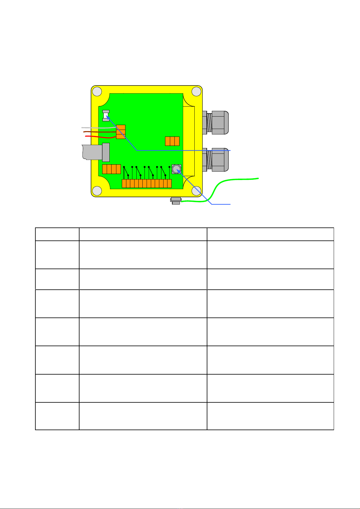
4.1.2 Electrical connection GTR 210 Comfort
Terminal Module assembly Connection
L
N
PE
Power supply
230V AC, 50Hz
L
N 230V AC, 50Hz
PE
I+
I-
Output current mA 4...20
GND
IN+
IN-
Digital input:
Connect with a zero-potential closing-
contact only
24V
digital input
123 Alarm 1
Zero-potential change-over contact
normally closed (nc)
common (com)
normally open (no)
456 Alarm 2
Zero-potential change-over contact
normally closed (nc)
common (com)
normally open (no)
789 Alarm 3
Zero-potential change-over contact
normally closed (nc)
common (com)
normally open (no)
101112 Fault
Zero-potential change-over contact
normally closed (nc)
common (com)
normally open (no)
Replace the fuses with identical types only !
Current rating of relais-contacts: 250 VAC, 8A / 30VDC, 8A
PE
L
N
I -
I +
IN+
IN-
230 VAC
50Hz
GND
I
24V
to sensor upper part
PE
Alarm 1
Alarm 2
Alarm 3
Fault
1
2
3
4
5
6
7
8
9
10
11
12
fuse F1: replace only with
type: SIBA 179200 1,6T
fuse F2: replace only with
type: Littlefuse HF451 375mA

ADOS GmbH GTR 210 Rev 1.16 Page 7
4.1.3 Installation of the Flow Adapter
In some applications, it is not possible to measure gas directly on site. In such cases, the gas can be
extracted and fed into the gas transmitter via a pump at an appropriate location.
In this case, the GTR210 can be fitted with a flow adapter.
The flow adapter is drawn through the pressure-proof sensor encapsulation of the gas transmitter. To
ensure that the conical nipple creates a secure seal, the encapsulation must be pushed into the flow
adapter as far as the limit stop.
Finally, the flow adapter is fixed in place with the grub screw.
%UEG
CH4
GTR 210
S
M
ESC
Alarm
Reset
‐
+055.2
Alarm: L1 L2
AdosGmbHwww.ados.de
GTR210
%LEL
CH4
grubscrew
sealing
ADOS GmbH GTR 210 Rev 1.16 Page 8
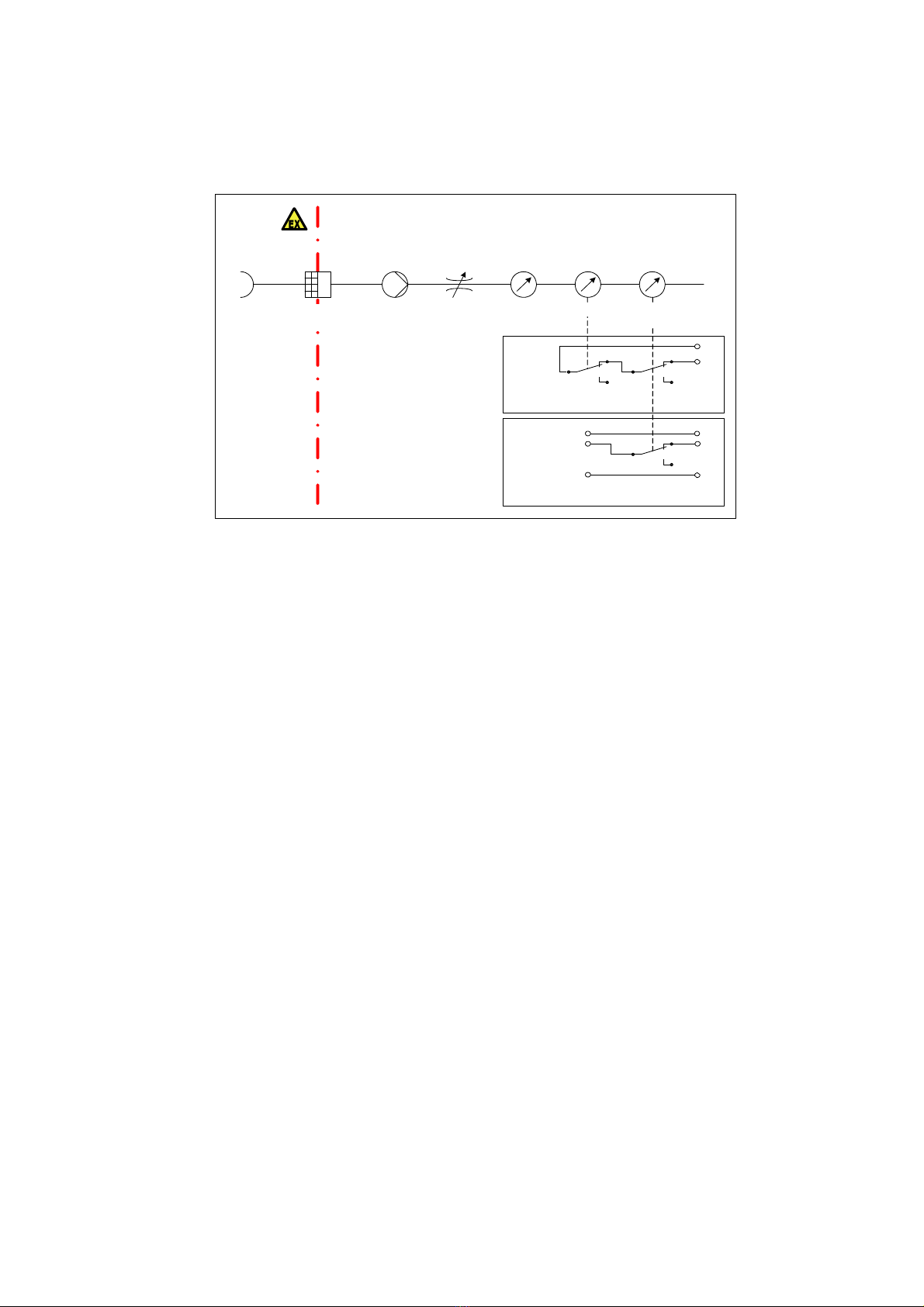
The following configuration should always be chosen for extracting the gas:
The flow monitor must be connected as illustrated. In the event of a fault in the flow rate, it interrupts the
current output signal of the GTR210.
With the comfort version of the GTR210, the contact of the flow monitor is connected in series with the
fault relay. The fault-status of the GTR210 is transferred on an equal footing with the fault flow rate
status.
The following points must be observed when using the flow adapter:
• If gas is extracted from a potentially explosive area, measures must be taken to eliminate the
risk of explosion (e.g. with a deflagration arrester).
• The flow rate must be 30 l/h ±30%.
• The pump must not build up a significant pressure inside the flow adapter. The increase in
pressure should not exceed 20 kPa.
• The flow rate must be monitored by a flow sensor.
• The inner diameter of the measuring gas line should be 6 mm.
• A dead time is added to the setting time t90 as the length of the measuring gas line increases.
With an inner diameter of 6 mm and a flow rate of 30 l/min, the following rule of thumb applies:
10 seconds dead time per metre of line. A measuring gas line length of 30 m should not be
exceeded.
• Some gases can be absorbed by certain plastics. For a holistic configuration, particularly for
the measuring gas line, components made from Teflon, stainless steel or viton should
therefore be selected.
• It must be ensured that the flow adapter is fitted correctly. It is imperative that the flow adapter
is fixed to the GTR210 with the grub screw. The leak-tightness of the system must be checked
after installation and following all maintenance work.
pump
deflagration‐
arrestor
needle‐valve rotar‐pipe
extraction
probe
GTR210faultrelais
(GTR210‐Comfortonly)
GTR210 flow‐meter‐
switch
24V
I
GND
24V
I
GND
GTR210currentoutput
EX‐area
Connectionscheme:
monitoringflowvia
fault‐relais
Connectionschemefor
monitoringflowvia
currentoutput
11
10
12

ADOS GmbH GTR 210 Rev 1.16 Page 9
4.1.4 Electrical connection GTR 210 Comfort with Controlbox:
Terminal Module assembly Connection
L
N
PE
Power supply
230 V AC 50Hz
L
N 230 V AC 50Hz
PE
I+
I-
Output current mA 4...20
GND
IN+
IN-
Digital Input bridge
24V
Power
Fault
Alarm
Buzzer
Button
Connection to external control box 24V 24V Supply
Power green LED
Fault yellow LED
Alarm red LED
Buzzer Alarm generator
Button Horn cancelling
10 11 12 Malfunction
Potential-free change-over contact
Opening contact (nc)
Centre terminal (com)
Closing contact (no)
PE
L
N
I‐
I+
IN+
IN‐
230VAC
50Hz
GND
I
24V
tosensorupperpart
PE
fault
10
11
12
FuseF1:replaceonlywith
SIBAtype1792001,6T
FuseF2:replaceonlywith
LittlefuseHF451375mA
24V
power
fault
alarm
horn
reset
connectionGTR210controlbox
ADOS GmbH GTR 210 Rev 1.16 Page 10
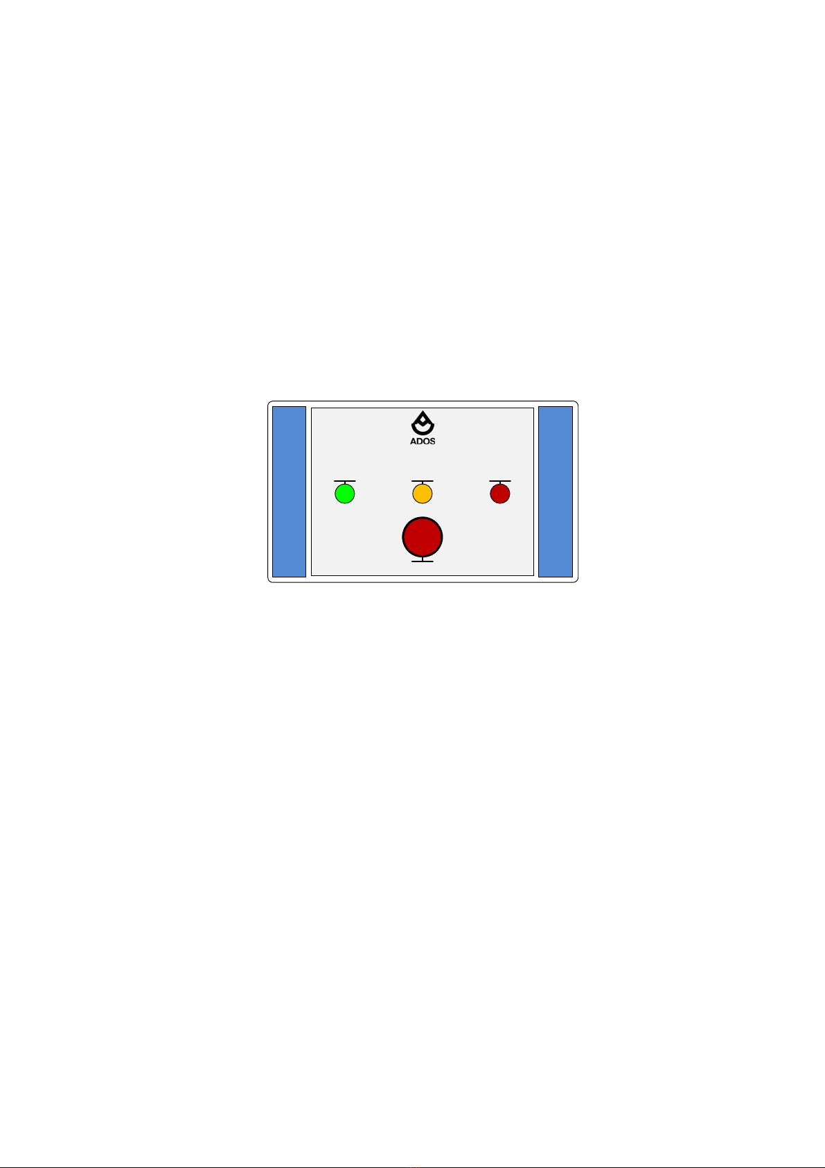
The external warning unit incorporates both optical and acoustic warning signals.
The warning signals are controlled by the GTR 210:
Green LED - Display Power supply
Yellow LED - Display Fault
Red LED - Display Alarm
Buzzer - acoustic indicator limit value 2
Button - possible acknowledgement limit value 3 (buzzer)
To enable the external buzzer in the control box to be acknowledged, Alarm 3 must be set to the horn
function.
Advice: the external Controlbox is not part of the EC Type Examination Certificate
Mess‐ u.RegeltechnikGmbHD‐52078Aachen
GTR210Control
PowerFaultAlarm1
Hornoff

ADOS GmbH GTR 210 Rev 1.16 Page 11
4.2 Notes on Safe Use of the Gas Transmitter
! Caution !
• The connection of the GTR 210 may be implemented in voltage-free status only.
• In case of explosion-protected implementation of the GTR 210, a cable gland with an EC
design type test certificate and the identification: II 2G Ex e II must be used. The
cable gland connection is included in the scope of delivery.
• The connection terminals must be tightened with a torque of 0.4 Nm
• The housing of the GTR 210 may be opened in voltage-free status only.
• The standard and the Comfort versions may not be installed under any circumstances
in an area that is classified as an Ex-zone!
• The Ex approval does not apply to use in oxygen-enriched atmospheres.
• Pellistors are not suitable for measuring combustible gases within atmospheres low in
oxygen.
• Sensor elements of the type TGS or pellistors can be poisoned by materials containing
traces of silicone, sulfur or halogenated, as well as by metals, such as for example lead,
so that the gas transmitter may not be used if any of these sensor toxins are present!
• At flow velocities greater than 4 m/s and with the presence of gas, increases in
measurements can occur that are greater than those permitted according to EN
60079-29-1.
• For the IP 66 alternative of the gas transmitter the t90 for propane is approx. 8 seconds
more than prescribed in the EN 60079-29-1. This fact has to be considered when
adjusting the alarm thresholds.
• Please bear also in mind that the response times t90 can fluctuate up to 10 %.
• For the IP54/IP66 versions of the transmitters is the t90 time for ammonia 380sec/549sec.
This fact has to be considered when adjusting the alarm thresholds.

ADOS GmbH GTR 210 Rev 1.16 Page 12
• The nc-contacts of the alarm relays (terminals 1, 4, 7 and 10) may only be used for
safety-related purposes if vibration loads cannot be avoided.
• When the “sensor-overload” message appears, the zero point and sensitivity must be
adjusted before using the device further. The device must be operated for at least 1
hour in pure air before this is done. The adjustment should checked regularly (e.g.
daily) until no further significant deviations are detected.
• The supply voltage at the connecting terminals of the GTR 210 must not be less than
18 V and not higher than 26 V
• The GTR 210 can be used only in the MED version on boats
• A usage of the transmitter on the boat bridge is not allowed
• The detection of oxygen on boats is not allowed
4.3 Commissioning
Commissioning is carried out after installation and following the electrical connection of the gas
transmitter:
• Switch on the supply voltage (switch on alarm control unit, e.g. FlexADOS 914).
A self-test takes place and the transmitter is initialised (see chapter 5.4). Once the self-test and
initialisation are complete, the warm-up period of the sensor starts. During this period, the sensor is in
maintenance-mode and there are no alarm outputs. Once the warm-up period has expired, the sensor
signal has stabilised. The transmitter is now in normal measuring mode.
Finally, the following initial checks must be carried out:
• Calibration check (see chapter 7.1)
• Check of signal transmission to evaluation unit (more detailed information on this can be found
in the operating manual for the evaluation unit used)
• Check of trigger of alarms
The gas transmitter is now operational.

ADOS GmbH GTR 210 Rev 1.16 Page 13
5. Operation
5.1 Device Display
The GTR 210 incorporates a graphics display. The upper line of the display indicates the status of the
gas transmitter, where faults and alarms are output. If no alarms or faults are present, the current date
is displayed. The measured value is indicated below the status line. The measured value is displayed
with sign, name of the target gas and the physical unit. In case of an equipment fault, the cause of the
fault is displayed instead of the measured value. On the lower line of the graphics display, a bar graph
is generated, which permits the user to evaluate the on-going measured value with reference to the
measuring-range end value. In addition, the alarm limits are displayed on the bar graph.
Also, the display is provided with a back lighting which displays the status of the gas transmitter:
1. Green: Normal measurement mode
2. Red: Overshooting / Undershooting of a limit value.
3. Yellow: Fault
13.05 12:30:59
+01 %LEL
CH4
Status indicator: Date and time
Unit of the measurement gas: %LEL
Name of the measurement gas: CH4
Bar graph: 1%
State of a limit value (60%)
Measured value: +1%
ALARM:L1 L2
+51 %LEL
CH4
Status indicator: Alarm 1, Alarm2
Unit of the measurement gas: %LEL
Name of the measurement gas: CH4
Bar graph: 51%
State of a limit value (60% not exceeded yet)
Measured value: +51%
State of a limit value (20% already exceeded)
FAULT
- Initialisation
- ROM-Test
Status indicator: Error
Fault description
Bar graph
ADOS GmbH GTR 210 Rev 1.16 Page 14
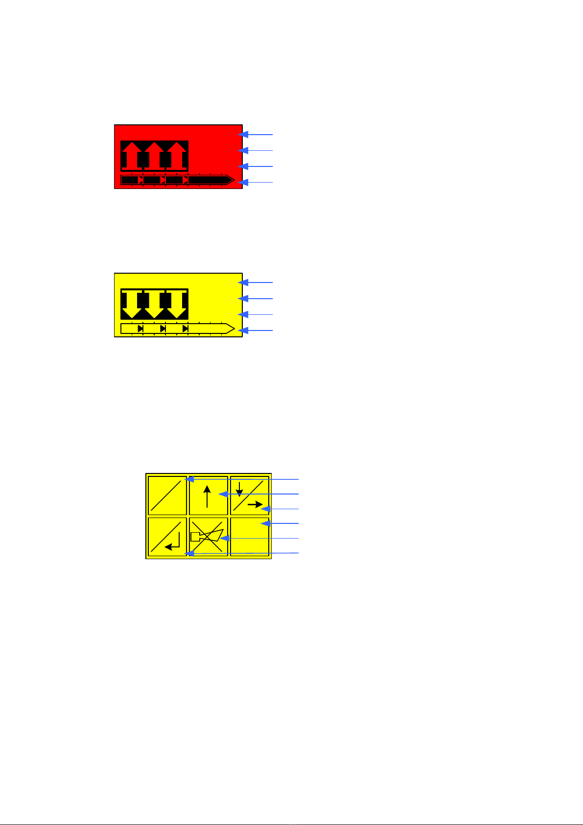
Measuring range overflow events are displayed with three arrows pointing upward:
Measuring range underflow events are displayed with three arrows pointing downward.
5.2 Keyboard
The keyboard is provided with six keys with which the device parameterization is carried out. In addition,
self-locking alarms can be acknowledged over the keyboard.
The keyboard consists of capacitive sensors. These are calibrated every two minutes. If a key is
“blocked”, it can be operated again after two minutes.
ESC key: With this key, inputs are rejected. If the ESC key is pressed longer than
4 seconds during operation, you reach the code input for the menu entry
ENTER key: Inputs are confirmed with this key.
UP key: With this key the current input value is increased. This key is also used for the
menu navigation.
DOWN key: With this key the current input value is reduced. This key is also used for the
menu navigation.
Alarm reset key With this key self-locking alarms are receipt. For this, the key
must be pressed longer than 4 seconds.
Horn reset key: With this key, the horn relay is receipt. For this, the key must be
pressed longer than 4 seconds.
ALARM:L1 L2 L3
%LEL
CH4
Status indicator: Alarm 1, Alarm 2, Alarm 3
Unit of the measurement gas: %LEL
Name of the measurement gas: CH4
Bar graph: >100%
FAULT
%LEL
CH4
Status indicator: Error
Unit of the measurement gas: %LEL
Name of the measurement gas: CH4
Bar graph: 0%
S
M
ESC
Alarm
Reset
ESC key
UP key
DOWN key
Alarm-reset key
Horn-reset key
ENTER key

ADOS GmbH GTR 210 Rev 1.16 Page 15
5.3 Alarms
In the user menu of the GTR 210, three limit values can be set, each of which triggers an alarm.
The first alarm is a pre-alarm, the limit value of which is always lower than that of the main alarm (except
for the measurement of oxygen). The user can adjust whether the first limit value is self-locking, or an
automatic acknowledgement is initiated if the measured gas concentration falls below the first limit
value.
The second alarm is the main alarm. The main alarm is always self-locking. The acknowledgement of
self-locking alarms is implemented using the key "Alarm reset", or with the Comfort version using an
external pushbutton, which is connected with the digital input of the transmitter. The acknowledgement
is accepted only if there is no further overshoot.
The third limit value is freely parametrizable. As well as the self-locking, the option "horn relay" can be
selected. If this option is selected, the third alarm can then also be acknowledged when the limit value
violation is still present. Additionally the acknowledgement is implemented automatically after 2 minutes.
This option applies to activation of acoustic alarm devices only.
For some applications (e.g. with the measurement of oxygen) it is required to reverse the monitoring
direction in the device parameters. This means that the alarms are triggered when the measuring value
has fallen below the limits. In case of the measurement of oxygen, the pre-alarm is always greater than
the master alarm. The display indicates the following example for oxygen monitoring in the ambient air.
The measuring range is 0-21 Vol% O2.
The monitoring direction of the limit values can be read on the bar graph.
ALARM: L2
+10 %LEL
CH4
Status indicator: Alarm 2
Unit of the measurement gas: %LEL
Name of the measurement gas: CH4
Bar graph: 10%
2. Limit value (40 %LEL CH4 )
Acknowlegement has not yet been initiated
+20 VOL%
O2
Status indicator: Date, time
Measurement display: +20 Vol% O2
Bar graph: 95% of the fullscale value
(fullscale = 21 Vol% O2)
Location of the limit values:
19 Vol% O2 = 90% fullscale
17 Vol% O2 = 80% fullscale
15 Vol% O2 = 70% fullscale
Monitoring of the limit value underflowing
13.05 12:30:59
Limit value marker for alarms which are
triggered with limit value overflow
Limit value marker for alarms which are
triggered with limit value underflow
ADOS GmbH GTR 210 Rev 1.16 Page 16
5.4 Trend Graph
The GTR 210 comes with 4 different trend graphs that are shown when pushing the arrow keys more
than two seconds in the measuring mode.
You can switch between the display of the different trend graphs by repeating the activation of the arrow
keys.
The following trend graphs including information about the measured gas concentration are available:
• 0...6 minutes
• 0...90 minutes
• 0...24 hours
• 0...18 days
Values above or below the measuring range are shown in a special way.
The same happens to unvalid data sets. These can occur if the gas transmitter enters the “failure” mode
and there are no measuring dates for the period that shall be displayed (e.g. after restarting the
transmitter).
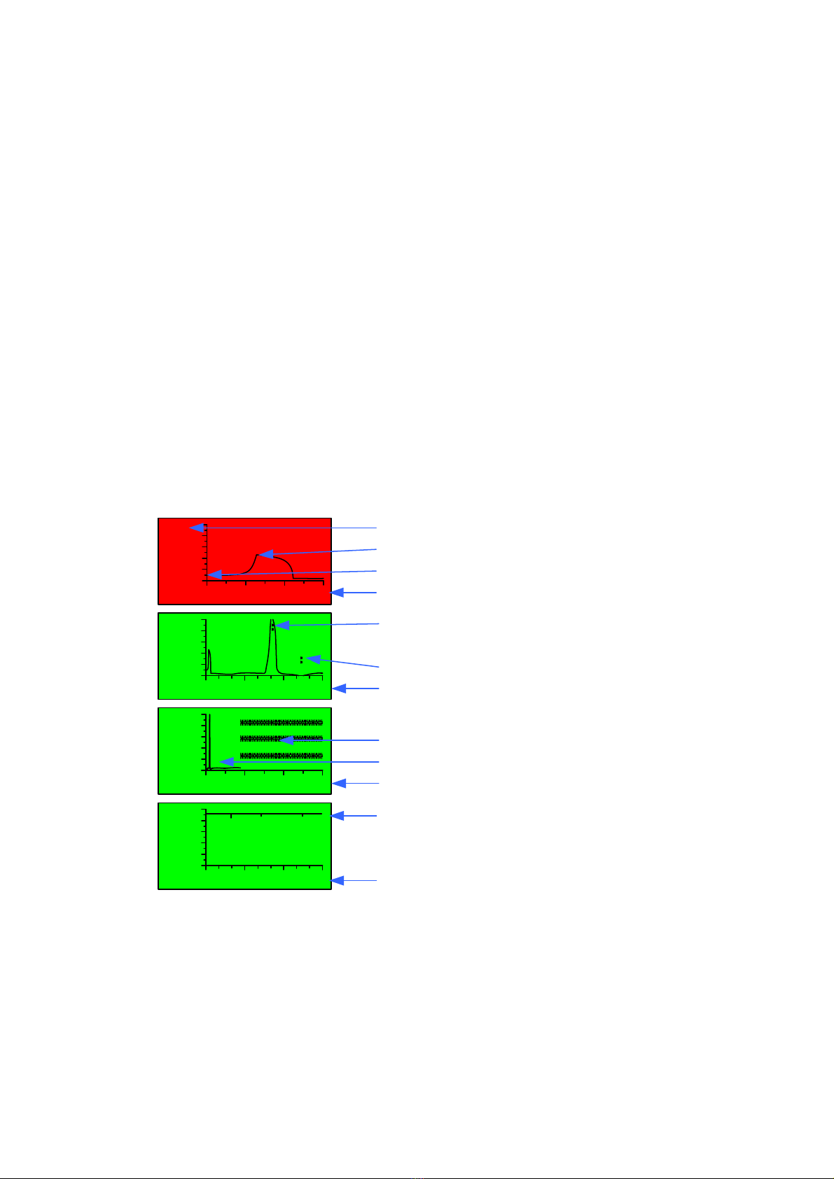
In the following example some typical trend graphs are shown:
These trend graphs always show the minimum and maximum values of the measured gas
concentrations within a certain period. This means for the first example 6 minutes / 90 pixel = 4 seconds.
The gas transmitter goes automatically back to the standard display in case of a changed status of
alarm or failure or if no button has been pushed for 20 seconds.
100
%LEL
CH4
Min: 0 30 60 90
100
%LEL
CH4
Hrs: 0 8 16 24
21.0
VOL%
O2
Days: 0 6 12 18
Overflowmarkingforthemeasuringvalue
Undeflowmarkingforthemeasuringvalue
Scalaofx‐axis:0– 90minutes
Illegalmeasuringvalues
Legalmeasuringvalues
Scalaofx‐axis:0– 24hours
Trendchartatoyxgen
Scalaofx‐axis:0– 18days
100
%LEL
CH4
Min: 0 2 4 6
Measuringrangey‐axis(100%LELCH4)
Measuringvaluebefore2minutes(50%LELCH4)
Actualmeasuringvalue(10%LELCH4)
Scalaofx‐axis:0– 6minutes
Table of contents
Other Ados Transmitter manuals


Popular Transmitter manuals by other brands

Moore Industries
Moore Industries TMZ user manual

Becker
Becker Centronic MemoControl MC511 Assembly and operating instructions

Beyerdynamic
Beyerdynamic Synexis TP8 Product information

Williams AV
Williams AV PPA T27 user manual

IFM
IFM TA1 Series operating instructions

Spektrum
Spektrum NX10SE instruction manual


