Ados T060E Operating manual

1569‐PT060EE1Rev.7Page1of62
ELECTRONIC WEIGHING TRANSMITTER
T060E
User and installation manual

1569‐PT060EE1Rev.7Page2of62
Tableofcontents
1.INTRODUCTION........................................................................................................................................ 4
1.1Overview...........................................................................................................................................................4
1.2Description........................................................................................................................................................4
1.2.1Options/ Versions .........................................................................................................................................4
1.3Use ....................................................................................................................................................................5
1.4Description of labels .........................................................................................................................................5
1.5Operating specifications....................................................................................................................................6
2.INSTRUMENT’S OPERATION .................................................................................................................. 7
2.1Turning on the instrument.................................................................................................................................7
2.2Transmitter’s functions .....................................................................................................................................8
2.2.1Management of the calibration .....................................................................................................................8
2.2.2Sum value function.......................................................................................................................................9
2.2.3Management of the zero................................................................................................................................9
2.2.4Signal filtering ............................................................................................................................................10
2.3Front panel ......................................................................................................................................................11
2.3.1Display........................................................................................................................................................11
2.3.2LED signals ................................................................................................................................................12
2.3.3Key functions..............................................................................................................................................12
2.4Self-troubleshooting........................................................................................................................................12
2.4.1Cell connection fault (FAIL) ......................................................................................................................12
2.5Management of relays.....................................................................................................................................13
3.INSTALLATION........................................................................................................................................ 14
3.1Receiving the material.....................................................................................................................................14
3.2Assembling the instrument..............................................................................................................................14
3.3Connections.....................................................................................................................................................15
3.4Rear panel .......................................................................................................................................................15
3.5Power supply tag.............................................................................................................................................15
3.6Connection to power supply (side B)..............................................................................................................16
3.6.1Version 110÷230V~ 24-48V~ ....................................................................................................................16
3.6.2Version 12÷24V ................................................................................................................................16
3.7Connection of load cells (side A)....................................................................................................................17
3.7.1Connection of load cells 1...........................................................................................................................17
3.7.2Connection of load cells 2 input .................................................................................................................19
3.7.3Wiring example (single weighing system)..................................................................................................20
3.7.4Wiring example (double weighing system) ................................................................................................21
3.8Connection of serial lines (side A)..................................................................................................................22
3.9Digital inputs (side B).....................................................................................................................................23
3.10Connection of relay outputs (side B)...............................................................................................................24
3.11Optional analogue output................................................................................................................................25
3.12PROFIBUS DP output (optional)....................................................................................................................26
4.MAINTENANCE ON THE INSTRUMENT................................................................................................ 27
4.1Preventive maintenance...................................................................................................................................27
4.2Corrective maintenance...................................................................................................................................27
5.MANAGEMENT OF THE INSTRUMENT................................................................................................. 28
5.1Introduction.....................................................................................................................................................28
5.2Operational sequence ......................................................................................................................................28
5.3Selection of the management functions...........................................................................................................28
5.3.1Time-Out function on the keys’ operation..................................................................................................28
5.4Configuration of operational parameters.........................................................................................................29
5.4.1Selection of operational parameters............................................................................................................29
5.4.2Editing of the value of operational parameters...........................................................................................30
5.4.3Setting the load cells’ signal.......................................................................................................................31
5.4.4Setting the weighing system capacity.........................................................................................................31
5.4.5Setting the system resolution......................................................................................................................31
5.4.6Average settings..........................................................................................................................................31
5.4.7Reference channe selection (only with instrument with double channel)...................................................32
5.4.8Scale factor selection ((only with instrument with double channel)...........................................................32
5.4.9Relay 1 function..........................................................................................................................................32
5.4.10Threshold value of relay 1......................................................................................................................33
5.4.11Hysteresis value of relay 1......................................................................................................................33

1569‐PT060EE1Rev.7Page3of62
5.4.12Minimum alarm time of relay 1..............................................................................................................33
5.4.13Minimum time to return to idle mode of relay 1 ....................................................................................33
5.4.14Enabling of FAIL function for channel 1...............................................................................................33
5.4.15Enabling of FAIL function for channel 2...............................................................................................33
5.4.16Function of serial port 1 .........................................................................................................................34
5.4.17Function of serial port 2 (excluded in case of PROFIBUS option)........................................................34
5.4.18Physical interface of serial port 1 ...........................................................................................................34
5.4.19Data transmitted on serial port 1 in continuous mode ............................................................................35
5.4.20Data transmitted on serial port 2 in continuous mode ............................................................................35
5.4.21Baud rate of serial port 1 ........................................................................................................................35
5.4.22Baud rate of serial port 2 (excluded in case of PROFIBUS option).......................................................36
5.4.23RS485 address of serial port 1................................................................................................................36
5.4.24RS485 address of serial port 2 (excluded in case of PROFIBUS option)...............................................36
5.4.25PROFIBUS address (only in case of PROFIBUS option)......................................................................37
5.4.26Analogue output .....................................................................................................................................37
5.4.27Definition of the type of analogue output...............................................................................................37
5.4.28Function of the analogue output.............................................................................................................37
5.4.29Full scale of the analogue output............................................................................................................38
5.4.30Digital filter setting.................................................................................................................................38
5.4.31Unbalanced load alarm setting ...............................................................................................................39
5.5Calibration.......................................................................................................................................................40
5.5.1Theoretical calibration procedure ...............................................................................................................40
5.5.2Permanent tare ............................................................................................................................................41
5.5.3Zero calibration...........................................................................................................................................42
5.5.4Span calibration ..........................................................................................................................................43
5.5.5Linearization...............................................................................................................................................44
5.5.6Analogue output adjustment.......................................................................................................................45
5.5.7Zero adjustment D/A ..................................................................................................................................46
5.5.8Full scale adjustment D/A...........................................................................................................................47
5.6Instrument test.................................................................................................................................................48
5.6.1Testing relay outputs and digital inputs......................................................................................................48
5.6.2Testing the analogue output........................................................................................................................49
5.6.3Testing load cell inputs...............................................................................................................................50
6.SERIAL PROTOCOL COMMUNICATION............................................................................................... 51
6.1Serial interface management...........................................................................................................................51
6.2String format in continuous mode...................................................................................................................52
6.2.1Calculation of the checksum.......................................................................................................................54
6.3String format in bi-directional mode...............................................................................................................54
6.3.1Weight request command ...........................................................................................................................54
6.4Bi-directional modality with MODBUS protocol...........................................................................................55
6.4.1T060E registers list.....................................................................................................................................56
6.4.2Status word coding......................................................................................................................................57
6.4.3List of Colis supported by T060E...............................................................................................................57
6.5PROFIBUS DP protocol .................................................................................................................................58
6.5.1Data from T060E weight transmitter ..........................................................................................................58
6.5.2Status word coding......................................................................................................................................58
6.5.3Command register.......................................................................................................................................58
6.5.4GDS file......................................................................................................................................................59
IMPORTANT
Theinstructionmanualmustbestoredproperlyandmadeavailabletoallauthorizedstaff.
Theinstructionmanualmustbepreserveduntiltheequipmentisputoutofservice.
AdditionalcopiescanberequestedtotheCompany’sassistancecentre.
Foranyclarificationsortechnicalinformation,pleasecontacttheCompany’sassistancecentre.

1569‐PT060EE1Rev.7Page4of62
1. INTRODUCTION
1.1 Overview
Thismanualdescribestheinstalling,programmingandtroubleshootingproceduresofweighttransmitter,mod.
T060E.Theinstructionmanualmustbestoredproperlyandmadeavailabletoallauthorisedstaff.
Theinstructionmanualmustbepreserveduntiltheequipmentisputoutofservice.Additionalcopiescanbe
requestedtotheCompany’sassistancecentre.
Foranyclarificationsortechnicalinformation,pleasecontacttheCompany’sassistancecentre.
Pleasenotethatanyinstrumentalterationswillvoidthewarranty,therefore,incaseofissues,contactexclusivelythe
Company’sassistancecentres.
Theuseroftheequipmentmustcomplywithallsafetystandardsapplicableinthecountrywherethedeviceisused,
andhemustalsoensurethattheequipmentisoperatedincompliancewithitsintendeduse,forhisownsafety.
1.2 Description
T060Eisaweighttransmitterdesignedforuseinweighingsystemsboastingstraingaugeloadcells.Themain
operatingcharacteristicsare:
Checkingof5basicthresholdsthatcanbeactivatedaccordingtoprogrammableoperatingparameters.
Managementof2inputsthatcanbeactivatedfortarefunction.
Interfacingtoexternalperipheralunitsthroughthemanagementofseriallines,withphysicalinterfaceRS232
orRS485.
Connectiontosupervisorysystemsthroughthemanagementofananalogueoutputundervoltageorcurrent.
1.2.1 Options/ Versions
T060Eoffersaseriesofoptions:
Inputforasecondweighingsystem
PROFIBUS‐DPinterface
T060EOP1OP2
D=DOUBLECHANNEL
P=PROFIBUSDP
1=110VAC
2=220VAC
3=24VAC
4=24VDC
Exampleofconfiguration:T060E1‐DPInstrumentintendedfor110VACpowersupply,featuringdoubleweighing
inputandPROFIBUS‐DPinterface.

1569‐PT060EE1Rev.7Page5of62
1.3 Use
THEFOLLOWINGISPROHIBITED:
Openandapplychangesand/oralterationstotheequipment.Ifthisclauseisnotrespected,the
warrantywillbevoided.
Wetand/orimmersetheinstrumentinanyliquid.
Exposeittostrongmagneticand/orelectricfields
Useinareassubjecttoexplosionhazard
Opentheequipment(itcanbeopenedexclusivelybyauthorisedpeople)
DANGER:
Cut‐offpowerbeforeperforminganyinterventionontheinstrument.
Inspectthepowersupplycableonaregularbasistocheckifthereareanydamages,andifso,
cut‐offpowerandreplaceit.
Themanufacturerdeclinesanyliabilityfordamagescausedtopeopleorobjectsderivedfroman
improperuseofthedevice.
1.4 Description of labels
ThelabelsaffixedonT060Econtain:
indicationofmanufacturer
identificationoftheinstrument'smodel
Instrument’sserialnumber
identificationoftheoperatingvoltage
CEmarking
Thelabelsmustnotberemoved;itisprohibitedtoaffixotherlabelstotheinstrumentwithoutthemanufacturer’s
authorisation.
Attheendofitsusefullife,the
productmustbedisposedofat
suitableseparatecollectioncentres.
Warning:pleaserefertothesupplied
documents
CEmarking
Warning:fulgurationhazard
Alternatingcurrent

1569‐PT060EE1Rev.7Page6of62
1.5 Operating specifications
Powersupply
From9÷24V ±10%(option)
110‐230~±10%
Absorbedpower10W
Operatingtemperaturefrom–10°Cto+40°C
Storagetemperaturefrom–20°Cto+50°C
Relativehumidity95%noncondensing
Maindisplay6digits,11mmLEDS
Statussignals85mmLEDS
Keyboard4mechanicalkeys
Loadcellinputpowersupply5V /114mA(max8cellsof350Ωinparallel)
Loadcellinput2inputpowersupply(optional)5V /114mA(max8cellsof350Ωinparallel)
Inputsensitivity0.02µV
Linearity
Temperaturedrift
Converter’sresolution24bit
Resolutionofdisplayedweight50000div.
Analoguesignal From–2mV/Vto+3mV/V
Conversionspeed100Hz
DigitalfilterSelectable
Serialports1RS232/RS485(fullduplex)opto‐isolated
Serialports1RS485(halfduplex)
Logicoutputs5SPSTrelayoutputs
Logicoutputs(optional)1SPSToutput(safetyoutput)
Logicinputs2digitalopto‐isolatedinputs
Opto‐isolatedanalogueoutput1selectable0÷10V/4÷20mA(activetype)
Resolution 16bit
Impedances Min.voltage10KΩ/Max.current500Ω
Linearity
Temperaturedrift
Sizes100x105x10mm
Assembly OnDINEN60715TH35bar.
ContainerABSRAL7035
FrontprotectiondegreeIP40/DINEN60529

1569‐PT060EE1Rev.7Page7of62
2. INSTRUMENT’S OPERATION
2.1 Turning on the instrument
Whentheinstrumentisturnedon,thefollowingsequenceofindicationsappearsontheprimarydisplay,approx.
everytwosecondsapart:
A D O S
T 0 6 0 E
R 1. 0 0 (Revisionoftheinstalledsoftware)
Whenreachingthisphase,theinstrumentbecomesimmediatelyoperativeandtheweightvalueappearsonthe
display.

1569‐PT060EE1Rev.7Page8of62
2.2 Transmitter’s functions
InstrumentT060Eisaweighttransmitterwithpotentialthresholdrelaymanagementfunction.
Therefore,itisnotatraditionalweighinginstrument,sinceGross,NetandTaremanagementfunctionsarenot
available.
OnlyZEROcorrectionscanbeexecuted(throughexternalinputs)withthepurposetorecoverzeroderivativesor
deviationsrelativetotheweighingsystem.
Theonboardrelaysaremanagedasalarmrelays,thereforetheyarealwayskeptenergizedandarede‐energizedin
caseofalarm.
2.2.1 Management of the calibration
T060Eforeseestheset‐upofatheoreticalcalibration.However,theoperatorcanexecutepotentialcorrectionsduring
thecalibrationphase.Theadvantageofthistypeofset‐upliesinthefactthatthesystemcarriesoutanautomatic
calibration,byknowingthecells’characteristics.
Thesystemisnotvalidincaseofloadcellsnotsupportingdirectlytheentireweightappliedtothesystem(e.g.incase
ofaweighingpinappliedtoaresultantofareturnsystem).Inthiscase,theoperatormustsettheweightvalueused
attheendofthemeasurementchain.
Forexample,incaseofaweighingpinappliedtothefixedcomponentofaliftingsystem,theoperatormustsetthe
valueactuallyliftedbythebridgecrane;forexample,incaseofpinweighing1tonandthecapacityofthebridge
craneconsistingof300tons.Inthiscase,thesignalwillbesetaccordingtothepin’sdatasheetandthecapacitywill
besetto300(correspondingto300tonsofthesystem'scapacity),whilethesensitivitywillbesetaccordingtothe
accuraciesidentifiedintheapplicationofthesystem(forexample,ifitweights200kg,thesensitivitymustbesetto
0.2).
Theresolution(divisionvalue)issettotheresultofthe60000divisions.Higherset‐upsarediscardedbythesystem.
Thesystem’sresolutionisgivenbytheratiobetweencapacityandresolution.
Asystemwitha100Kgcellandaresolutionof0.01isasystemconsistingof10000divisions.
SE G N 1
T060Eforeseesloadcellswithmaximumsignalof3.5mV/V.
PO R T 1
Thevaluesetinthisparameterconstitutesthefullscaleoftheweighingsystem.Itforeseesamaximumvalueof
100000divisions.
SE N S 1
Thevaluecanbeselectedwithintherangefrom50to0.001divisions.
Thechangeofbothsystemcapacityandloadcellsignal(mV/V)causetheclearanceofcalibrationdata
(linearizationsincluded)alreadycarriedout,ofsetpointsvaluesandtheanalogoutputdata.

1569‐PT060EE1Rev.7Page9of62
2.2.2 Sum value function
TheT060Ethedoublechannelweighingversion(Doption)foreseesthepossibilitytohandlethesumvalueofthetwo
channels.Thevaluecanbedisplayedbothpushingandinassociationwithoneormorethresholdrelays
alarms(seechapter2.5).Incaseofsystemswithcapacityordifferentunitmeasure,theoperatormusrealignthe
valuetothesameunitmeasure,decidingwhichofthetwochannelsmustbetakenasreferencechannel.
I.E.:
Channel1F.S.10.00tandchannel21000kfF.S.consideringchannel1asreferencechannel(parameterPRIOR),we
shouldreturnthechannel2toadisplayint.
InordertogetthistheT060EwithparameterMULTIPallowsdividingormultiplyingthechannelvalue.
Inourexampledividingby1000thechannel2valueisdisplayedasforchannel1int.
Accordingtodifferentsystemscapacities,multiplyingordividing,itispossibletosumvalueswiththesamemeasure
unit.
2.2.3 Management of the zero
Theexternalinputscanbeusedtoresetpotentialzeroderivativesordeviationsrelativetotheweighingsystem.The
AZMlimitisvalidinbothways,thereforetheactualfieldis‐100.0%.+100.0%.
Theinputisactiveontheclosingpanel.
Weightresettingiscarriedoutafterconversionandlinearizationoperationswhicharenotinfluenced,causinga
verticaltranslationofthetransmitter’sresponsecurve.
Zeroingaffectsalltransmitters’functions:display,serialtransmission,analogueoutputandthresholdmanagement
arealllinkedtothecorrectweightvalue.
Theresetvalueislostiftheequipmentisturnedoff.
Thenon‐resettotalweightvaluecanbecheckedlocallybypressingkeyDEC:bykeepingthiskeypressed,the
instrumentdisplaysthetotalweightvalue.
1569‐PT060EE1Rev.7Page10of62
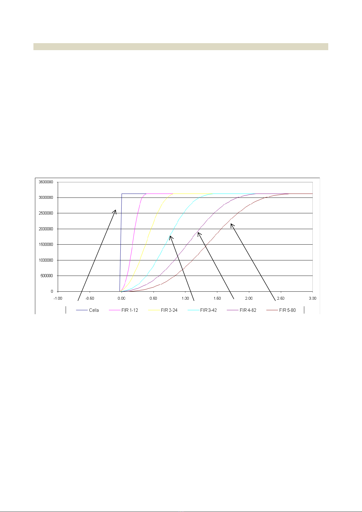
2.2.4 Signal filtering
Theinstrumentallowsintroducingfilteringmethodsofthesignalcomingfromloadcells(FIRfilters).Thismethodis
basedonDigitalSignalProcessing(DSP)modesandallowshandlingatbest,signalscontainingstrongharmonic
components(e.g.generatedbymixers).
Duringtheconfigurationphase,itispossibletoselectthreetypicalfilters(withmovingaverage)and5DSPfilters.
Theformerallowquickerresponsetimesbutarelesseffectivewithregardstointerferences,thereforetheymustbe
usedwhenextremelyquickweightvariationsmustbedetected.
Thelatterallowmitigatinginterferences(sincetheyboastahigherfilteringeffect)atthedisadvantageoftheresponse
timetoweightvariations.
Inbothcases,thehigheristhefilter’snumber,thegreateristhefilteringeffectandtheresponsetimetoaweight
variation.
Forexample,theresponsetoastepweightvariationisshowninthechartbelow,basedontheselectedfilter.
ThechartshowsthatfilterFIR1boastsaresponsetimeofapprox.0.2seconds,whilefilterFIR5boastsaresponse
timeofapprox.2.5seconds.

1569‐PT060EE1Rev.7Page11of62
2.3 Front panel
2.3.1 Display
Innormaloperatingconditions,thedisplayindicatestheweightvaluesaccordingtothefollowingcriteria:
theirrelevantinitialzerosarenotdisplayed
the“minus”sign(incaseofnegativeweightvalues)isdisplayedinthefirstleftdigit
Ifthenegativeweightvalueisofsixdigits(e.g.‐324210),thefirstleftdigitwillindicatethe“minus”signandthe
weightvalue,alternatively.
Ifthenegativeweightvalueisofsevendigits,thelesssignificantfivedigitsaredisplayedandthemessagestarts
flashinginordertoindicatethepresenceofanon‐visibleinitial“1”.Thefirstleftdigitwillindicatethe“minus”
signandtheweightvalue,alternatively.
Theweightindicationlimitsare:
Lowerlimit:‐20%offullscale
upperlimit:120%offullscale
Iftheweightislowerthanthelowerlimit,thefollowingindicationisdisplayed:
- - U L - -
Iftheweightisgreaterthantheupperlimit,thefollowingindicationisdisplayed:
- - O L - -
2 1 0 0 0 0

1569‐PT060EE1Rev.7Page12of62
2.3.2 LED signals
ThemeaningofthemessagesprovidedbythesignalLEDSlocatedontheinstrument’sfrontpanelisthefollowing:
RL1÷RL5TheLEDisonduetothetriggeringoftherelativethreshold
SRTheLEDisontonotifythetriggeringofthesafetysignal
TXTheLEDflashestosignalthetransmissionactivityofserialport1.
RXTheLEDflashestosignalthereceivingactivityofserialport1.
2.3.3 Key functions
Iftheinstrumentisinoperatingmode,itallowscommutingthereading(iftheinstrumentforesees
theoptionalsecondchannel)todisplaytheweightvalueofthesecondchannelortotalvalue
(channel1+channel2).
Iftheinstrumentisinconfigurationmode,itallowsbrowsingforwardthemenuitemsand
increasingtheparameters’value.
Iftheinstrumentisinoperatingmodeandtheweightwaszeroed,thedisplaywillindicatethe
valuebypressingthiskey(fortheselectedchannel).
Iftheinstrumentisinconfigurationmode,itallowsbrowsingbackwardthemenuitemsand
decreasingtheparameters’value.
Iftheinstrumentisinoperatingmode,itallowsenteringinconfigurationmode.
Iftheinstrumentisinconfigurationmode,thekeywillconfirmtheselectionsmade.
Iftheinstrumentisinoperatingmode,ithasnofunction.
Iftheinstrumentisinconfigurationmode,thiskeywillcanceltheselectionsmade.
2.4 Self-troubleshooting
2.4.1 Cell connection fault (FAIL)
Theinstrumentconstantlychecksthecorrectconnectionoftheloadcell(interruptionandshort‐circuitofthesignal
andpowersupplyconnections)and,incaseananomalyisdetected,aFAILinternalsignalisgenerated.
ByprogrammingoneormorerelaysasFAIL,inadditiontothemessageappearingonthedisplay,allchannel’srelays
areforcedinalarmstatus(theyarede‐energized).Forexample,byprogrammingFAIL1,allrelayssetwithalarm
thresholdsonchannel1and/orthetotal,areforcedinalarmstatus.

1569‐PT060EE1Rev.7Page13of62
2.5 Management of relays
Thebasicinstrumentisequippedwithfiverelaysthatcanbeconfiguredasrequired.
Agenerallyopencontact(NA)notundervoltageisavailableforeachrelay.
Therelays’operationislinkedtotheconditionsdefinedintheconfigurationphase.
Therelays’commutationtakesplacewhenthethresholdvaluesetintheconfigurationphase(SET#parameter)is
reachedandremainsinthisconditionforatimeframeequaltoorexceedingthealarmminimumtime(DAL#
parameter).Itisrestoredinnormalconditionswhentheweightvalueisdroppedbelowthevaluedeterminedbythe
sumofthethresholdvalueandtheconfiguredhysteresisvalue(DB#parameter)andremainsinthisconditionfora
timeframeequaltoorexceedingtheminimumnormaltime(DOH#parameter).
Thechangeoftherelayoperationcausetheclearanceofsetpointsvalues.
Eachrelaycanbeconfiguredtooperateinoneofthefollowingmodes:
F A I L 1 Loadcellconnectionfault(FAIL).Thealarmstatusistriggered
whentheFAILconditionispresent.
L O N 1 Minimumalarm(LON)
Thealarmstatusistriggeredwhentheweightvalueislower
thanorequaltothethresholdvalue.
H I N 1 Maximumalarm(HIN)
Thealarmstatusistriggeredwhentheweightvalueisgreater
thanorequaltothethresholdvalue.
L O G 1
Minimumalarm(LOG).Thealarmistriggered,regardlessof
theresetvalue.
Thealarmstatusistriggeredwhentheweightvalueislower
thanorequaltothethresholdvalue.
H I G 1
Maximumalarm(HIG).Thealarmistriggered,regardlessof
theresetvalue.
Thealarmstatusistriggeredwhentheweightvalueislower
thanorequaltothethresholdvalue.
T O T N Alarmonthetotalvalueofthetwochannels(TOTG).The
alarmstatusistriggeredwhentheweightvalueisgreater
thanorequaltothethresholdvalue.
T O T G
Alarmonthetotalvalueofthetwochannels(TOTG).The
alarmistriggered,regardlessoftheresetvalue.
Thealarmstatusistriggeredwhentheweightvalueisgreater
thanorequaltothethresholdvalue.
O N Therelayiskeptconstantlyenergized.

1569‐PT060EE1Rev.7Page14of62
3. INSTALLATION
3.1 Receiving the material
Beforesigningthetransportdocument,makesuretherearenodamagestotheequipmentcausedduringtransport
andifso,notifythecarrier.
Inadditiontotheinstrument,thefollowingmustbepresent:
1seriesoffemaleflyingterminalsforconnectingthepowersupplyandinputandoutputsignals
1copyoftheinstructionmanual
1copyoftheinstrument’stestingreport(checkthattheserialnumberappearingintherelativelabel
correspondstotheserialnumberindicatedonthetestingsheet).
INPUT100‐240V~
10W50/60Hz
MODELT060E1
S.N.20160234
Eachdevicefeaturestherequiredinformationforproperidentification:modelandserialnumber.
Thisdata,togetherwiththesoftwareversion,mustbeindicatedwhenrequestinginformation.
3.2 Assembling the instrument
WARNING
Makesurethatthesupplyvoltagefallswithintheinstrument’sallowedlimits.
Makesurethatitispossibletodisconnectpowerduringinstallationand/ormaintenancephases.
Performagroundconnectionifrequired.
Itisrecommendedtouseashieldedcableforcell’sinputsignals,analogueoutputsandseriallines.
Usetroughsforcell’sinputsignals,analogueoutputsandseriallines,whichareseparatefromthoseofpowersignals.
Connectthepanelonwhichtheinstrumentisinstalledtotheground.
Theinstrument’soutputrelaysmustbeusedtocontroltherelays’coils(whichnominalcurrentmustfallwithin
declaredlimitsandanyhow,usingsuitablearcsuppressiondevices),logicinputsorsignalLEDS;theymustnotcontrol
powersignals.

1569‐PT060EE1Rev.7Page15of62
3.3 Connections
Allinstrument’sconnectionsarecarriedoutonthesideoftheinstrument.
3.4 Rear panel
Alabelcontainingscreen‐printedindicationstofacilitatetheoperatorincarryingoutcablingoperationsisaffixedon
thesidesoftheinstrumentnearterminals.
SIDE B
SIDE A
3.5 Power supply tag
Beforeconnectingtheequipmenttoapowersource,makesurethattheselectedvalueonthelabelcorrespondsto
theforeseenvoltage.Iftheforeseenvaluesdiffersfromthevoltageindicatedonthetag,donotconnectthe
equipmentandcontactexclusivelyacompany’sassistancecentretochangetheversionifneeded.

1569‐PT060EE1Rev.7Page16of62
3.6 Connection to power supply (side B)
3.6.1 Version 110÷230V~ 24-48V~
INDICATIONFUNCTIONTERMINAL
NNeutral2
LLine1
EGround3
Connecttheinstrument’ssafetygroundterminaltothesystem’sgroundbarthroughflexiblecable.
3.6.2 Version 12÷24V
INDICATIONFUNCTIONTERMINAL
++12÷241
‐02
1 2 3 4 5 6 7 8 9 10 11 12 13 14 15 16 17 18
OUT 1
OUT 4
OUT 2
OUT 1
OUT 2
OUT 4
OUT 3
OUT 3
G SAFETY OUT
V SAFETY OUT
OUT 5
OUT 5
INP 2
INP 1
C INP
100-240VAC
124VAC 48VAC
LL
NN
EE
2
3
24VDC
-
+L
E
N

1569‐PT060EE1Rev.7Page17of62
3.7 Connection of load cells (side A)
Thecablecomingfromtheloadcellsorjunctionboxmustbeconnectedtotheterminalslocatedontherearofthe
instrumentandcalledLOADCELL1.
Connectionbetweentheloadcellandtheinstrumentmustbecarriedoutwithashieldedcable.Thecable’sshield
mustbeconnectedtotheground.
Connectionmusttakeplacerespectingthecolourcodeindicatedontheloadcells.
T060foreseesthestandardconnectionof6‐wireloadcells.Incaseofconnectionof4‐wireloadcells,connectthe
referencewirestotherelativepolaritiesofthepowersupplycables.
MAKESURETHECONNECTIONCABLEBETWEENLOADCELLSANDINSTRUMENTISDUCTEDINTROUGHSSEPARATE
FROMTHOSEOFPOWERLINES,INORDERTOAVOIDCOUPLINGTHATMAYPREJUDICETHEMEASUREMENT
ACCURACY.
3.7.1 Connection of load cells 1
LC1
INDICATIONFUNCTION TERMINAL
+A+Excitation 39
‐A‐Excitation 38
+S+Signal37
‐S‐Signal 36
+R+Reference 35
‐R‐Reference 34
3128 29 30
-S
+R
-R
3432 33
+S
3635 37
-A
+A
3938
-R
+R
-S
+S
-A
+A
LOAD CELL 2 LOAD CELL 1
232019 2221 2524 2726
SGND 3
IOUT+
VOUT+
SGND 2
-RS485
+RS485
SGND 1
-RS485/RX
+RS485/TX
SERIAL
OUT 1
SERIAL
OUT 2
ANALOG
OUTPUT
OPTO OPTO

1569‐PT060EE1Rev.7Page18of62
Incaseof4‐wireconnection,short‐circuittheterminals–Excitationwith‐Referenceand+Excitationwith+
Reference.
CONNECTIONWITH4‐WIRELOADCELLS
CONNECTIONWITH6‐WIRELOADCELLS

1569‐PT060EE1Rev.7Page19of62
3.7.2 Connection of load cells 2 input
T060Eforeseesanoptionalsecondloadcellsinput.Theconsiderationsmadeforthemainchannelalsoapplyforthe
optionalinputchannel.
LC2
INDICATIONFUNCTION TERMINAL
+A+Excitation 33
‐A‐Excitation 32
+S+Signal 31
‐S‐Signal 30
+R+Reference 29
‐R‐Reference 28
3128 29 30
-S
+R
-R
3432 33
+S
3635 37
-A
+A
3938
-R
+R
-S
+S
-A
+A
LOAD CELL 2 LOAD CELL 1
232019 2221 2524 2726
SGND 3
IOUT+
VOUT+
SGND 2
-RS485
+RS485
SGND 1
-RS485/RX
+RS485/TX
SERIAL
OUT 1
SERIAL
OUT 2
ANALOG
OUTPUT
OPTO OPTO

1569‐PT060EE1Rev.7Page20of62
3.7.3 Wiring example (single weighing system)
Inthecaseofplantconsistsofasingleweighingsystemwithoneormorecellsconnectedinparallelthewiringmust
bemadeonchannel1(seediagramasanexample)
Exampleofasystemconsistingofasingleweighingsystemwithonlytwoloadcellsinparallel
Table of contents
Other Ados Transmitter manuals


Popular Transmitter manuals by other brands


Electronic Broadcast Equipment
Electronic Broadcast Equipment SIRIO 2000T User and maintenance manual

NIVELCO
NIVELCO EasyTREK SP-300 Installation and programming manual

SMW
SMW LNB-LINK user guide

Moseley
Moseley DSP6000A user manual

Indexa
Indexa DF-100 operating instructions

YOKOGAWA
YOKOGAWA EJA210E user manual

NET-K
NET-K WT-1550-EM30 operating manual

Omega Engineering
Omega Engineering CYTX231 Series user guide

Ametek Drexelbrook
Ametek Drexelbrook Universal Lite 509-1 Series Installation and operating instructions

Toyo
Toyo SOT-EQ80 Series Operation manual

Hydac
Hydac HFT 2100 user manual

BSi
BSi Mini-Tx UHD product manual