SGM LEKTRA TC26 User manual

825B030D
TC26/27/28/29
Compact capacitance level transmitter with settable relay built-in
Technical Data
TC26-9 Mechanical installation
Enclosure material: PP+Carbon steel
Mechanical installation: Bajonet
(to be insert into IP65 enclosure)
Mechanical protection: IP50
Electrical connection: 2 x 6pole plug-in connectors
Working temperature: -30 to +80°C
Power supply depend to the model:
TC26 24Vdc, TC27 24Vac,
TC28 115Vac, TC29 230Vac
Power consumption: max 2,5W (1,5W Vdc)
Analog output: 4÷20mA max load 500 ohm
Relays output: 1 x SPDT 2A, 230Vac (resistive)
Serial port: RS485
Measure range: 20pF÷10.000pF
Temperature compensation: by ref. internal capacitor
Linearity: 0,5%
Calibration: two push-buttons, for self-acquisition
LEDs display: green LED flashing=measure
Fix=calibration
yellow LEDs for rel1 action
The TC26-9 insert must be lodge into the IP65 capacitance-
sensor head commection.
Important to screw tight the cover of the head connection and
the cable gland in order to grant the sensor IP65.
Thanks to the bajonet fixing-system, to insert or remove the
TC26-9 from the head connection need to push and rotate.
Rotate clock-wise to fix into the head
Rotate reverse-clock-wise to remove from the head
LEVEL 4-20mA transmitter + 1 settable relay insert, digital
tecnology, termal-drift compensation, two pushbuttons or
RS485 port for calibration. Local or remote calibration
possibility.
TC26-9 General
fig.3
fig.1
fig.2
applied solutions for the applications

TC26-9 Electrical Connections
The TC26-9 capacitance transmitters have the following
power-supply, electrical connections:
fig.7
fig.6
TC26-9 Setpoint Calibration
The TC26-9 relay(RL1) operates as max level alarm (threshold1). This configuration is the default factory configuration and
it can be changed by means RS485 port and the TC S/W communication.
To calibrate the threshold1 of maximum levelneeds to move the level at the threshold point than:
press simultaneously P1 and P2, release them and verify that “Mode led” will stay fix on. Press P2 and release it, press P1
and release it. Wait until “Mode led” is flashing again before move the level. The threshold of RL1 has been memorised.
On fig.7 the relay status.
The current consumption is less than 1,5W for Vdc power supply
and 2,5W for Vac power supply.
TheTC26-29capacitancetrannsmittersarelodgedintothesensor
capacitancehead connections; remove the cover unscrewingand
opening the upper part, gain the access to two 6-pole plug-in
connectors. Electrical connection must be made with a multi-wires
roundcableofproperdiameter,otherwise thesealofthe cablegland
may be impaired. No special cable or coax-cable are requests for
compactversion,and no practicedistancelimits.Forthe Vdc power
supply take in consideration that the negative of the power supply
is electrically connected to the negative output current. For the Vac
powersupply versions,fromthepower supplyandthe outputcurrent
there is a galvanically separation. A special J-box with P1 and P2
calibration push buttons built-in is available on request for remote-
calibration.
Available a RS485 serial port to communicate to PC or PLC. On
requestthe “TC”S/Wcommunication forPCand theRS485/RS232
conversionmoduleareavailable.“TC”allowaPCTC26-29configuration
and calibration, see the relevant documentation.
Always connect the electrode to vessel ground (PA). For this purpose
there is a terminal on the side of the housing or on the mechanical
connection. This connection is also used to supply the ground
reference potential as well as to drain off electrostatic charges.
TC27 = 24Vac, TC28 = 115Vac, TC29 = 230Vac
TC26 = 24Vdc
fig.4
fig.5
GREEN GREY
GREEN GREY

TC26-9 4-20mA Calibration
b)
Refers to the “TC” S/W operating manual
The TC26-9 calibration can be done in two different ways:
a) By means the P1 and P2 push-buttons.
b) With PC or PLC soft. communication with RS485 port.
a)
To calibrate by-means 2 push-buttons P1 and P2 (see figure), needs to lodge the “TC26-29” into the head connection of the
capacitance sensor and to install into the vessel or tank to be measured.
Depends to the possibility to reach easily 0% and 100% level is possible to use “Full-Empty Calibration” or , when 0% and
100% level can’t be reached the “High and Low-point Calibration” methods can be used, see fig.8.
fig.8
Full, Empty Calibration(fig.9)
The TC26-9 transmitter can be calibrate in
respectively at the level of 0% and 100%
level, in order to memorise the relevant
capacity electronically.
In the measuring mode, the TC has the
Mode LED flashing.
To calibrate 0% (4mA) needs to have the
level at the 0%.
Press simultaneously P1 and P2, release
them and verify that “Mode led” will stay fix
lightened.
Press two times P1. The measured
capacity has been memorised and
associated to 4mA output.
Press simultaneously P1 and P2 again to
switch in measure mode (Mode led
flashing.
To calibrate 100% (20mA) needs to have
the level at the 100%.
Press simultaneously P1 and P2, release
them and verify that “Mode led” will stay fix
lightened.
Press two times P2. The measured
capacity has been memorised and
associated to 20mA output.
Press simultaneously P1 and P2 again to
switch in measure mode (Mode led
flashing.
Important!
The calibration can be done first with
empty and than with full (as the above
procedure) or first with full and than with
empty as well.
fig.9
Full(100%), Empty(0%) Calibration
TC26-9 4-20mA Calibration (intermediate High-point , Low-point)
TC26-9 Factory test certificate TC26-9 Warranty
fig.11
.
fig.10
In conformity to the company and ceck procedure I certify
that the equipment:
TC2 ............. Serial n. ......................
is conform to the technical requirements on Technical Data
and it is made in conformity to the SGM-LEKTRA procedu-
re
Quality Control Manager
.............................................................................................
Production and ceck date
.............................................................................................
The warranty expires when damages they have provoked from
the use not quite or from not correct installations. The
warranty is valid for a period of 12 months from the sell behind
presentation of this manual. All the reparations in warranty will
have realized in our workshop in Rodano (MI), the costs of
dismuonting and reinstalling of the device and the costs of the
transport will be paid by the customer.
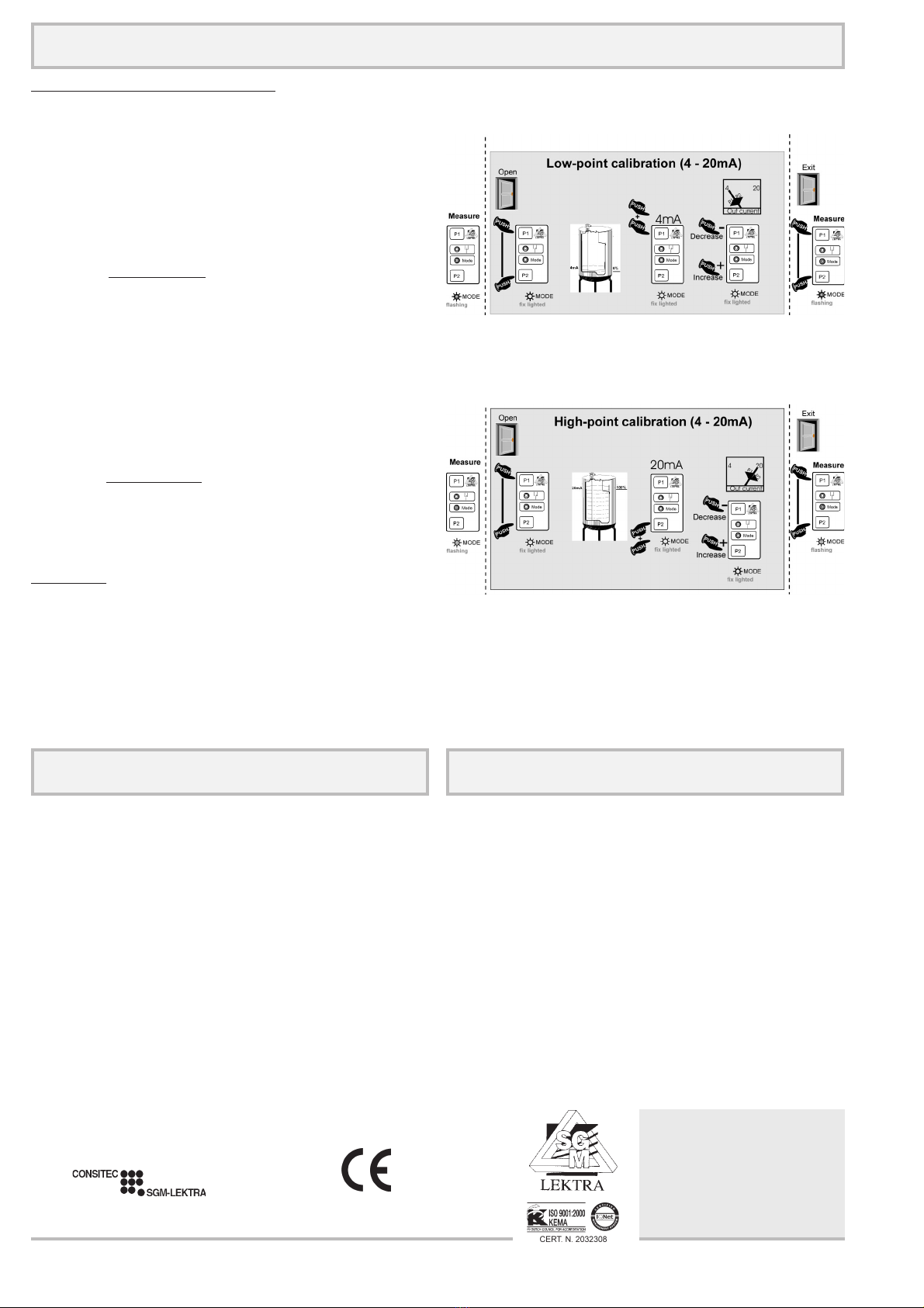
High-point, Low-point Calibration
If only a limitate level variation is possible, the calibration of
the TC26-9 is still possible.
Need to connect a current-meter on the TC26-9 output current
and verify the present level point at which make the calibration.
Supposely you are on the Low-point calibration, and the
relevant level is 26%(8,16mA) than;
Press simultaneously P1 and P2, release them and verify
that “Mode led” will stay fix lightened, Open the calibration
mode. Press two times P1. The measured capacity has been
associated at the moment to 4mA output. Now, pushing few
times the P2 key, increase the output current from 4mA to
8,16mA, (P1 decrease the value). Once the correct current-
output is displayed in to the current meter; press
simultaneously P1 and P2 again to Exit from calibration going
in measure mode (Mode led flashing).
Increase the level of your product as much as possible, for
instance up to 58%(13,28mA) than;
Press simultaneously P1 and P2, release them and verify
that “Mode led” will stay fix lightened, Open the calibration
mode. Press two times P2. The measured capacity has been
associated at the moment to 20mA output. Now, pushing few
times the P1 key, decrease the output current from 20mA to
13,28mA, (P2 increase the value) ; press simultaneously P1
and P2 again to Exit from calibration going in measure mode
(Mode led flashing).
Important!
The calibration can be done first with low-point and than with
high-point (as the above procedure) or first with high-point and
than with low-point as well.
documentation subject to technical change with no prior warning
SGM LEKTRA s.r.l.
Via Papa Giovanni XXIII, 49
20090 Rodano (Milano)
tel. ++39 0295328257 r.a.
fax ++39 0295328321
e-mail: inf[email protected]
web: www.sgm-lektra.com
This manual suits for next models
3
Other SGM LEKTRA Transmitter manuals

SGM LEKTRA
SGM LEKTRA RPL75 User manual

SGM LEKTRA
SGM LEKTRA RPL81 User manual

SGM LEKTRA
SGM LEKTRA METER Series Quick start guide

SGM LEKTRA
SGM LEKTRA PTU50 Guide

SGM LEKTRA
SGM LEKTRA RPL75 User manual

SGM LEKTRA
SGM LEKTRA PTU51 User manual

SGM LEKTRA
SGM LEKTRA PTU05 User manual

SGM LEKTRA
SGM LEKTRA PTU50 User manual

SGM LEKTRA
SGM LEKTRA KPT Guide

SGM LEKTRA
SGM LEKTRA FLOWMETER Guide


