Ados T060E PN Series Operating manual

1710‐PT060PNERev.0Page1of57
ELECTRONIC WEIGHING TRANSMITTER
(PROFINET VERSION)
T060Ex-PN
User and installation manual

1710‐PT060PNERev.0Page2of57
Tableofcontents
1.INTRODUCTION........................................................................................................................................ 4
1.1Overview...........................................................................................................................................................4
1.2Description........................................................................................................................................................4
1.2.1Options/ Versions .........................................................................................................................................4
1.3Use ....................................................................................................................................................................5
1.4Description of labels .........................................................................................................................................5
1.5Operating specifications....................................................................................................................................6
2.INSTRUMENT’S OPERATION .................................................................................................................. 7
2.1Turning on the instrument.................................................................................................................................7
2.2Transmitter’s functions .....................................................................................................................................8
2.2.1Management of the calibration .....................................................................................................................8
2.2.2Sum value function.......................................................................................................................................9
2.2.3Management of the zero................................................................................................................................9
2.2.4Signal filtering ............................................................................................................................................10
2.3Front panel ......................................................................................................................................................11
2.3.1Display........................................................................................................................................................11
2.3.2LED signals ................................................................................................................................................12
2.3.3Key functions..............................................................................................................................................12
2.4Self-troubleshooting........................................................................................................................................12
2.4.1Cell connection fault (FAIL) ......................................................................................................................12
2.5Management of relays.....................................................................................................................................13
3.INSTALLATION........................................................................................................................................ 14
3.1Receiving the material.....................................................................................................................................14
3.2Assembling the instrument..............................................................................................................................14
3.3Connections.....................................................................................................................................................15
3.4Rear panel .......................................................................................................................................................15
3.5Power supply tag.............................................................................................................................................15
3.6Connection to power supply (side B)..............................................................................................................16
3.6.1Version 110÷230V~ 24-48V~ ....................................................................................................................16
3.6.2Version 12÷24V ................................................................................................................................16
3.7Connection of load cells (side A)....................................................................................................................17
3.7.1Connection of load cells 1...........................................................................................................................17
3.7.2Connection of load cells 2 input .................................................................................................................19
3.7.3Wiring example (single weighing system)..................................................................................................20
3.7.4Wiring example (double weighing system) ................................................................................................21
3.8Connection of serial lines (side A)..................................................................................................................22
3.9Digital inputs (side B).....................................................................................................................................23
3.10Connection of relay outputs (side B)...............................................................................................................24
3.11Optional analogue output................................................................................................................................25
3.12PROFINET output ..........................................................................................................................................26
4.MAINTENANCE ON THE INSTRUMENT................................................................................................ 27
4.1Preventive maintenance...................................................................................................................................27
4.2Corrective maintenance...................................................................................................................................27
5.MANAGEMENT OF THE INSTRUMENT................................................................................................. 28
5.1Introduction.....................................................................................................................................................28
5.2Operational sequence ......................................................................................................................................28
5.3Selection of the management functions...........................................................................................................28
5.3.1Time-Out function on the keys’ operation..................................................................................................28
5.4Configuration of operational parameters.........................................................................................................29
5.4.1Selection of operational parameters............................................................................................................29
5.4.2Editing of the value of operational parameters...........................................................................................30
5.4.3Setting the load cells’ signal.......................................................................................................................31
5.4.4Setting the weighing system capacity.........................................................................................................31
5.4.5Setting the system resolution......................................................................................................................31
5.4.6Average settings..........................................................................................................................................31
5.4.7Reference channe selection (only with instrument with double channel)...................................................32
5.4.8Scale factor selection ((only with instrument with double channel)...........................................................32
5.4.9Relay 1 function..........................................................................................................................................32
5.4.10Threshold value of relay 1......................................................................................................................33
5.4.11Hysteresis value of relay 1......................................................................................................................33

1710‐PT060PNERev.0Page3of57
5.4.12Minimum alarm time of relay 1..............................................................................................................33
5.4.13Minimum time to return to idle mode of relay 1 ....................................................................................33
5.4.14Enabling of FAIL function for channel 1...............................................................................................33
5.4.15Enabling of FAIL function for channel 2...............................................................................................33
5.4.16Function of serial port 1 .........................................................................................................................34
5.4.17Physical interface of serial port 1 ...........................................................................................................34
5.4.18Data transmitted on serial port 1 in continuous mode............................................................................35
5.4.19Baud rate of serial port 1 ........................................................................................................................35
5.4.20RS485 address of serial port 1................................................................................................................35
5.4.21Analogue output .....................................................................................................................................36
5.4.22Definition of the type of analogue output...............................................................................................36
5.4.23Function of the analogue output.............................................................................................................36
5.4.24Full scale of the analogue output............................................................................................................37
5.5Calibration.......................................................................................................................................................38
5.5.1Theoretical calibration procedure ...............................................................................................................38
5.5.2Permanent tare ............................................................................................................................................39
5.5.3Zero calibration...........................................................................................................................................40
5.5.4Span calibration ..........................................................................................................................................41
5.5.5Linearization...............................................................................................................................................42
5.5.6Analogue output adjustment.......................................................................................................................43
5.5.7Zero adjustment D/A ..................................................................................................................................44
5.5.8Full scale adjustment D/A...........................................................................................................................45
5.6Instrument test.................................................................................................................................................46
5.6.1Testing relay outputs and digital inputs......................................................................................................46
5.6.2Testing the analogue output........................................................................................................................47
5.6.3Testing load cell inputs...............................................................................................................................48
6.SERIAL PROTOCOL COMMUNICATION............................................................................................... 49
6.1Serial interface management...........................................................................................................................49
6.2String format in continuous mode...................................................................................................................50
6.2.1Calculation of the checksum.......................................................................................................................52
6.3String format in bi-directional mode...............................................................................................................52
6.3.1Weight request command ...........................................................................................................................52
6.4Bi-directional modality with MODBUS protocol...........................................................................................53
6.4.1T060E registers list.....................................................................................................................................54
6.4.2Status word coding......................................................................................................................................55
6.4.3List of Colis supported by T060E...............................................................................................................55
6.5PROFINET protocol .......................................................................................................................................56
6.5.1Data from T060E weight transmitter ..........................................................................................................56
6.5.2Status word coding......................................................................................................................................56
6.5.3Command register.......................................................................................................................................56
IMPORTANT
The instruction manual must be stored properly and made available to all authorized staff.
The instruction manual must be preserved until the equipment is put out of service.
Additional copies can be requested to the Company’s assistance centre.
For any clarifications or technical information, please contact the Company’s assistance centre.

1710‐PT060PNERev.0Page4of57
1. INTRODUCTION
1.1 Overview
Thismanualdescribestheinstalling,programmingandtroubleshootingproceduresofweighttransmitter,mod.
T060E.Theinstructionmanualmustbestoredproperlyandmadeavailabletoallauthorisedstaff.
Theinstructionmanualmustbepreserveduntiltheequipmentisputoutofservice.Additionalcopiescanbe
requestedtotheCompany’sassistancecentre.
Foranyclarificationsortechnicalinformation,pleasecontacttheCompany’sassistancecentre.
Pleasenotethatanyinstrumentalterationswillvoidthewarranty,therefore,incaseofissues,contactexclusivelythe
Company’sassistancecentres.
Theuseroftheequipmentmustcomplywithallsafetystandardsapplicableinthecountrywherethedeviceisused,
andhemustalsoensurethattheequipmentisoperatedincompliancewithitsintendeduse,forhisownsafety.
1.2 Description
T060Eisaweighttransmitterdesignedforuseinweighingsystemsboastingstraingaugeloadcells.Themain
operatingcharacteristicsare:
Checkingof5basicthresholdsthatcanbeactivatedaccordingtoprogrammableoperatingparameters.
Managementof2inputsthatcanbeactivatedfortarefunction.
Interfacingtoexternalperipheralunitsthroughthemanagementofseriallines,withphysicalinterfaceRS232
orRS485.
Connectiontosupervisorysystemsthroughthemanagementofananalogueoutputundervoltageorcurrent.
1.2.1 Options/ Versions
T060Eoffersaseriesofoptions:
Inputforasecondweighingsystem
PROFIBUS‐DPinterface
PROFINETexternalinterface
T060EOP1OP2
D=DOUBLECHANNEL
P=PROFIBUSDP
PN =PROFINET
1=110VAC
2=220VAC
3=24VAC
4=24VDC
Exampleofconfiguration:T060E1‐DPInstrumentintendedfor110VACpowersupply,featuringdoubleweighing
inputandPROFIBUS‐DPinterface.

1710‐PT060PNERev.0Page5of57
1.3 Use
THEFOLLOWINGISPROHIBITED:
Openandapplychangesand/oralterationstotheequipment.Ifthisclauseisnotrespected,the
warrantywillbevoided.
Wetand/orimmersetheinstrumentinanyliquid.
Exposeittostrongmagneticand/orelectricfields
Useinareassubjecttoexplosionhazard
Opentheequipment(itcanbeopenedexclusivelybyauthorisedpeople)
DANGER:
Cut‐offpowerbeforeperforminganyinterventionontheinstrument.
Inspectthepowersupplycableonaregularbasistocheckifthereareanydamages,andifso,
cut‐offpowerandreplaceit.
Themanufacturerdeclinesanyliabilityfordamagescausedtopeopleorobjectsderivedfroman
improperuseofthedevice.
1.4 Description of labels
ThelabelsaffixedonT060Econtain:
indicationofmanufacturer
identificationoftheinstrument'smodel
Instrument’sserialnumber
identificationoftheoperatingvoltage
CEmarking
Thelabelsmustnotberemoved;itisprohibitedtoaffixotherlabelstotheinstrumentwithoutthemanufacturer’s
authorisation.
Attheendofitsusefullife,the
productmustbedisposedofat
suitableseparatecollectioncentres.
Warning:pleaserefertothesupplied
documents
CEmarking
Warning:fulgurationhazard
Alternatingcurrent

1710‐PT060PNERev.0Page6of57
1.5 Operating specifications
Powersupply
From9÷24V ±10%(option)
110‐230~±10%
Absorbedpower10W
Operatingtemperaturefrom–10°Cto+40°C
Storagetemperaturefrom–20°Cto+50°C
Relativehumidity95%noncondensing
Maindisplay6digits,11mmLEDS
Statussignals85mmLEDS
Keyboard4mechanicalkeys
Loadcellinputpowersupply5V /114mA(max8cellsof350Ωinparallel)
Loadcellinput2inputpowersupply(optional)5V /114mA(max8cellsof350Ωinparallel)
Inputsensitivity0.02µV
Linearity
Temperaturedrift
Converter’sresolution24bit
Resolutionofdisplayedweight50000div.
Analoguesignal From–2mV/Vto+3mV/V
Conversionspeed100Hz
DigitalfilterSelectable
Serialports1RS232/RS485(fullduplex)opto‐isolated
Serialports1RS485(halfduplex)
Logicoutputs5SPSTrelayoutputs
Logicoutputs(optional)1SPSToutput(safetyoutput)
Logicinputs2digitalopto‐isolatedinputs
Opto‐isolatedanalogueoutput1selectable0÷10V/4÷20mA(activetype)
Resolution 16bit
Impedances Min.voltage10KΩ/Max.current500Ω
Linearity
Temperaturedrift
Sizes100x105x10mm
Assembly OnDINEN60715TH35bar.
ContainerABSRAL7035
FrontprotectiondegreeIP40/DINEN60529

1710‐PT060PNERev.0Page7of57
2. INSTRUMENT’S OPERATION
2.1 Turning on the instrument
Whentheinstrumentisturnedon,thefollowingsequenceofindicationsappearsontheprimarydisplay,approx.
everytwosecondsapart:
A D O S
T 0 6 0 E
R 1. 0 5 (Revisionoftheinstalledsoftware)
Whenreachingthisphase,theinstrumentbecomesimmediatelyoperativeandtheweightvalueappearsonthe
display.

1710‐PT060PNERev.0Page8of57
2.2 Transmitter’s functions
InstrumentT060Eisaweighttransmitterwithpotentialthresholdrelaymanagementfunction.
Therefore,itisnotatraditionalweighinginstrument,sinceGross,NetandTaremanagementfunctionsarenot
available.
OnlyZEROcorrectionscanbeexecuted(throughexternalinputs)withthepurposetorecoverzeroderivativesor
deviationsrelativetotheweighingsystem.
Theonboardrelaysaremanagedasalarmrelays,thereforetheyarealwayskeptenergizedandarede‐energizedin
caseofalarm.
2.2.1 Management of the calibration
T060Eforeseestheset‐upofatheoreticalcalibration.However,theoperatorcanexecutepotentialcorrectionsduring
thecalibrationphase.Theadvantageofthistypeofset‐upliesinthefactthatthesystemcarriesoutanautomatic
calibration,byknowingthecells’characteristics.
Thesystemisnotvalidincaseofloadcellsnotsupportingdirectlytheentireweightappliedtothesystem(e.g.incase
ofaweighingpinappliedtoaresultantofareturnsystem).Inthiscase,theoperatormustsettheweightvalueused
attheendofthemeasurementchain.
Forexample,incaseofaweighingpinappliedtothefixedcomponentofaliftingsystem,theoperatormustsetthe
valueactuallyliftedbythebridgecrane;forexample,incaseofpinweighing1tonandthecapacityofthebridge
craneconsistingof300tons.Inthiscase,thesignalwillbesetaccordingtothepin’sdatasheetandthecapacitywill
besetto300(correspondingto300tonsofthesystem'scapacity),whilethesensitivitywillbesetaccordingtothe
accuraciesidentifiedintheapplicationofthesystem(forexample,ifitweights200kg,thesensitivitymustbesetto
0.2).
Theresolution(divisionvalue)issettotheresultofthe60000divisions.Higherset‐upsarediscardedbythesystem.
Thesystem’sresolutionisgivenbytheratiobetweencapacityandresolution.
Asystemwitha100Kgcellandaresolutionof0.01isasystemconsistingof10000divisions.
SE G N 1
T060Eforeseesloadcellswithmaximumsignalof3.5mV/V.
PO R T 1
Thevaluesetinthisparameterconstitutesthefullscaleoftheweighingsystem.Itforeseesamaximumvalueof
100000divisions.
SE N S 1
Thevaluecanbeselectedwithintherangefrom50to0.001divisions.
Thechangeofbothsystemcapacityandloadcellsignal(mV/V)causetheclearanceofcalibrationdata
(linearizationsincluded)alreadycarriedout,ofsetpointsvaluesandtheanalogoutputdata.

1710‐PT060PNERev.0Page9of57
2.2.2 Sum value function
TheT060Eithedoublechannelweighingversion(Doption)foreseesthepossibilitytohandlethesumvalueofthetwo
channels.Thevaluecanbedisplayedbothpushingandinassociationwithoneormorethresholdrelays
alarms(seechapter2.5).Incaseofsystemswithcapacityordifferentunitmeasure,theoperatormusrealignthe
valuetothesameunitmeasure,decidingwhichofthetwochannelsmustbetakenasreferencechannel.
I.E.:
Channel1F.S.10.00tandchannel21000kfF.S.consideringchannel1asreferencechannel(parameterPRIOR),we
shouldreturnthechannel2toadisplayint.
InordertogetthistheT060EwithparameterMULTIPallowsdividingormultiplyingthechannelvalue.
Inourexampledividingby1000thechannel2valueisdisplayedasforchannel1int.
Accordingtodifferentsystemscapacities,multiplyingordividing,itispossibletosumvalueswiththesamemeasure
unit.
2.2.3 Management of the zero
Theexternalinputscanbeusedtoresetpotentialzeroderivativesordeviationsrelativetotheweighingsystem.The
AZMlimitisvalidinbothways,thereforetheactualfieldis‐100.0%.+100.0%.
Theinputisactiveontheclosingpanel.
Weightresettingiscarriedoutafterconversionandlinearizationoperationswhicharenotinfluenced,causinga
verticaltranslationofthetransmitter’sresponsecurve.
Zeroingaffectsalltransmitters’functions:display,serialtransmission,analogueoutputandthresholdmanagement
arealllinkedtothecorrectweightvalue.
Theresetvalueislostiftheequipmentisturnedoff.
Thenon‐resettotalweightvaluecanbecheckedlocallybypressingkeyDEC:bykeepingthiskeypressed,the
instrumentdisplaysthetotalweightvalue.
1710‐PT060PNERev.0Page10of57
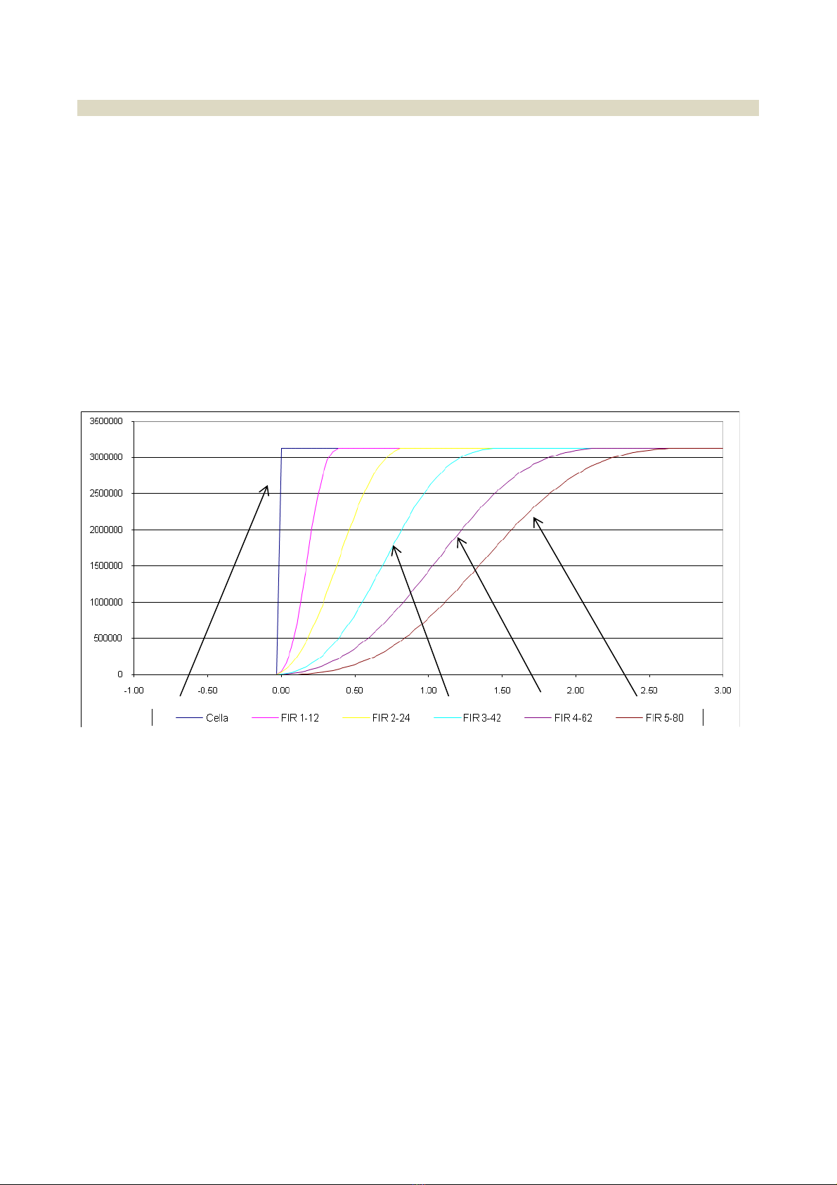
2.2.4 Signal filtering
Theinstrumentallowsintroducingfilteringmethodsofthesignalcomingfromloadcells(FIRfilters).Thismethodis
basedonDigitalSignalProcessing(DSP)modesandallowshandlingatbest,signalscontainingstrongharmonic
components(e.g.generatedbymixers).
Duringtheconfigurationphase,itispossibletoselectthreetypicalfilters(withmovingaverage)and5DSPfilters.
Theformerallowquickerresponsetimesbutarelesseffectivewithregardstointerferences,thereforetheymustbe
usedwhenextremelyquickweightvariationsmustbedetected.
Thelatterallowmitigatinginterferences(sincetheyboastahigherfilteringeffect)atthedisadvantageoftheresponse
timetoweightvariations.
Inbothcases,thehigheristhefilter’snumber,thegreateristhefilteringeffectandtheresponsetimetoaweight
variation.
Forexample,theresponsetoastepweightvariationisshowninthechartbelow,basedontheselectedfilter.
ThechartshowsthatfilterFIR1boastsaresponsetimeofapprox.0.2seconds,whilefilterFIR5boastsaresponse
timeofapprox.2.5seconds.
1710‐PT060PNERev.0Page11of57
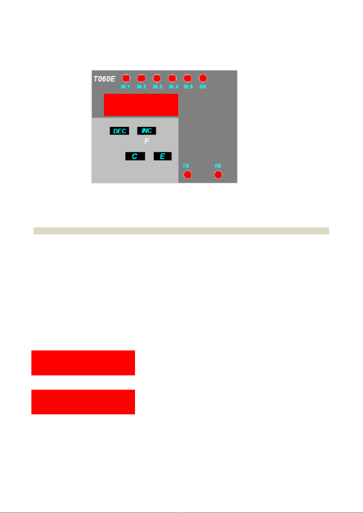
2.3 Front panel
2.3.1 Display
Innormaloperatingconditions,thedisplayindicatestheweightvaluesaccordingtothefollowingcriteria:
theirrelevantinitialzerosarenotdisplayed
the“minus”sign(incaseofnegativeweightvalues)isdisplayedinthefirstleftdigit
Ifthenegativeweightvalueisofsixdigits(e.g.‐324210),thefirstleftdigitwillindicatethe“minus”signandthe
weightvalue,alternatively.
Ifthenegativeweightvalueisofsevendigits,thelesssignificantfivedigitsaredisplayedandthemessagestarts
flashinginordertoindicatethepresenceofanon‐visibleinitial“1”.Thefirstleftdigitwillindicatethe“minus”
signandtheweightvalue,alternatively.
Theweightindicationlimitsare:
Lowerlimit:‐20%offullscale
upperlimit:120%offullscale
Iftheweightislowerthanthelowerlimit,thefollowingindicationisdisplayed:
- - U L - -
Iftheweightisgreaterthantheupperlimit,thefollowingindicationisdisplayed:
- - O L - -
2 1 0 0 0 0

1710‐PT060PNERev.0Page12of57
2.3.2 LED signals
ThemeaningofthemessagesprovidedbythesignalLEDSlocatedontheinstrument’sfrontpanelisthefollowing:
RL1÷RL5TheLEDisonduetothetriggeringoftherelativethreshold
SRTheLEDisontonotifythetriggeringofthesafetysignal
TXTheLEDflashestosignalthetransmissionactivityofserialport1.
RXTheLEDflashestosignalthereceivingactivityofserialport1.
2.3.3 Key functions
Iftheinstrumentisinoperatingmode,itallowscommutingthereading(iftheinstrumentforesees
theoptionalsecondchannel)todisplaytheweightvalueofthesecondchannelortotalvalue
(channel1+channel2).
Iftheinstrumentisinconfigurationmode,itallowsbrowsingforwardthemenuitemsand
increasingtheparameters’value.
Iftheinstrumentisinoperatingmodeandtheweightwaszeroed,thedisplaywillindicatethe
valuebypressingthiskey(fortheselectedchannel).
Iftheinstrumentisinconfigurationmode,itallowsbrowsingbackwardthemenuitemsand
decreasingtheparameters’value.
Iftheinstrumentisinoperatingmode,itallowsenteringinconfigurationmode.
Iftheinstrumentisinconfigurationmode,thekeywillconfirmtheselectionsmade.
Iftheinstrumentisinoperatingmode,ithasnofunction.
Iftheinstrumentisinconfigurationmode,thiskeywillcanceltheselectionsmade.
2.4 Self-troubleshooting
2.4.1 Cell connection fault (FAIL)
Theinstrumentconstantlychecksthecorrectconnectionoftheloadcell(interruptionandshort‐circuitofthesignal
andpowersupplyconnections)and,incaseananomalyisdetected,aFAILinternalsignalisgenerated.
ByprogrammingoneormorerelaysasFAIL,inadditiontothemessageappearingonthedisplay,allchannel’srelays
areforcedinalarmstatus(theyarede‐energized).Forexample,byprogrammingFAIL1,allrelayssetwithalarm
thresholdsonchannel1and/orthetotal,areforcedinalarmstatus.

1710‐PT060PNERev.0Page13of57
2.5 Management of relays
Thebasicinstrumentisequippedwithfiverelaysthatcanbeconfiguredasrequired.
Agenerallyopencontact(NA)notundervoltageisavailableforeachrelay.
Therelays’operationislinkedtotheconditionsdefinedintheconfigurationphase.
Therelays’commutationtakesplacewhenthethresholdvaluesetintheconfigurationphase(SET#parameter)is
reachedandremainsinthisconditionforatimeframeequaltoorexceedingthealarmminimumtime(DAL#
parameter).Itisrestoredinnormalconditionswhentheweightvalueisdroppedbelowthevaluedeterminedbythe
sumofthethresholdvalueandtheconfiguredhysteresisvalue(DB#parameter)andremainsinthisconditionfora
timeframeequaltoorexceedingtheminimumnormaltime(DOH#parameter).
Thechangeoftherelayoperationcausetheclearanceofsetpointsvalues.
Eachrelaycanbeconfiguredtooperateinoneofthefollowingmodes:
F A I L 1 Loadcellconnectionfault(FAIL).Thealarmstatusistriggered
whentheFAILconditionispresent.
L O N 1 Minimumalarm(LON)
Thealarmstatusistriggeredwhentheweightvalueislower
thanorequaltothethresholdvalue.
H I N 1 Maximumalarm(HIN)
Thealarmstatusistriggeredwhentheweightvalueisgreater
thanorequaltothethresholdvalue.
L O G 1
Minimumalarm(LOG).Thealarmistriggered,regardlessof
theresetvalue.
Thealarmstatusistriggeredwhentheweightvalueislower
thanorequaltothethresholdvalue.
H I G 1
Maximumalarm(HIG).Thealarmistriggered,regardlessof
theresetvalue.
Thealarmstatusistriggeredwhentheweightvalueislower
thanorequaltothethresholdvalue.
T O T N Alarmonthetotalvalueofthetwochannels(TOTG).The
alarmstatusistriggeredwhentheweightvalueisgreater
thanorequaltothethresholdvalue.
T O T G
Alarmonthetotalvalueofthetwochannels(TOTG).The
alarmistriggered,regardlessoftheresetvalue.
Thealarmstatusistriggeredwhentheweightvalueisgreater
thanorequaltothethresholdvalue.
O N Therelayiskeptconstantlyenergized.

1710‐PT060PNERev.0Page14of57
3. INSTALLATION
3.1 Receiving the material
Beforesigningthetransportdocument,makesuretherearenodamagestotheequipmentcausedduringtransport
andifso,notifythecarrier.
Inadditiontotheinstrument,thefollowingmustbepresent:
1seriesoffemaleflyingterminalsforconnectingthepowersupplyandinputandoutputsignals
1copyoftheinstructionmanual
1copyoftheinstrument’stestingreport(checkthattheserialnumberappearingintherelativelabel
correspondstotheserialnumberindicatedonthetestingsheet).
INPUT100‐240V~
10W50/60Hz
MODELT060E1
S.N.20160234
Eachdevicefeaturestherequiredinformationforproperidentification:modelandserialnumber.
Thisdata,togetherwiththesoftwareversion,mustbeindicatedwhenrequestinginformation.
3.2 Assembling the instrument
WARNING
Makesurethatthesupplyvoltagefallswithintheinstrument’sallowedlimits.
Makesurethatitispossibletodisconnectpowerduringinstallationand/ormaintenancephases.
Performagroundconnectionifrequired.
Itisrecommendedtouseashieldedcableforcell’sinputsignals,analogueoutputsandseriallines.
Usetroughsforcell’sinputsignals,analogueoutputsandseriallines,whichareseparatefromthoseofpowersignals.
Connectthepanelonwhichtheinstrumentisinstalledtotheground.
Theinstrument’soutputrelaysmustbeusedtocontroltherelays’coils(whichnominalcurrentmustfallwithin
declaredlimitsandanyhow,usingsuitablearcsuppressiondevices),logicinputsorsignalLEDS;theymustnotcontrol
powersignals.

1710‐PT060PNERev.0Page15of57
3.3 Connections
Allinstrument’sconnectionsarecarriedoutonthesideoftheinstrument.
3.4 Rear panel
Alabelcontainingscreen‐printedindicationstofacilitatetheoperatorincarryingoutcablingoperationsisaffixedon
thesidesoftheinstrumentnearterminals.
SIDE B
SIDE A
3.5 Power supply tag
Beforeconnectingtheequipmenttoapowersource,makesurethattheselectedvalueonthelabelcorrespondsto
theforeseenvoltage.Iftheforeseenvaluesdiffersfromthevoltageindicatedonthetag,donotconnectthe
equipmentandcontactexclusivelyacompany’sassistancecentretochangetheversionifneeded.
1710‐PT060PNERev.0Page16of57
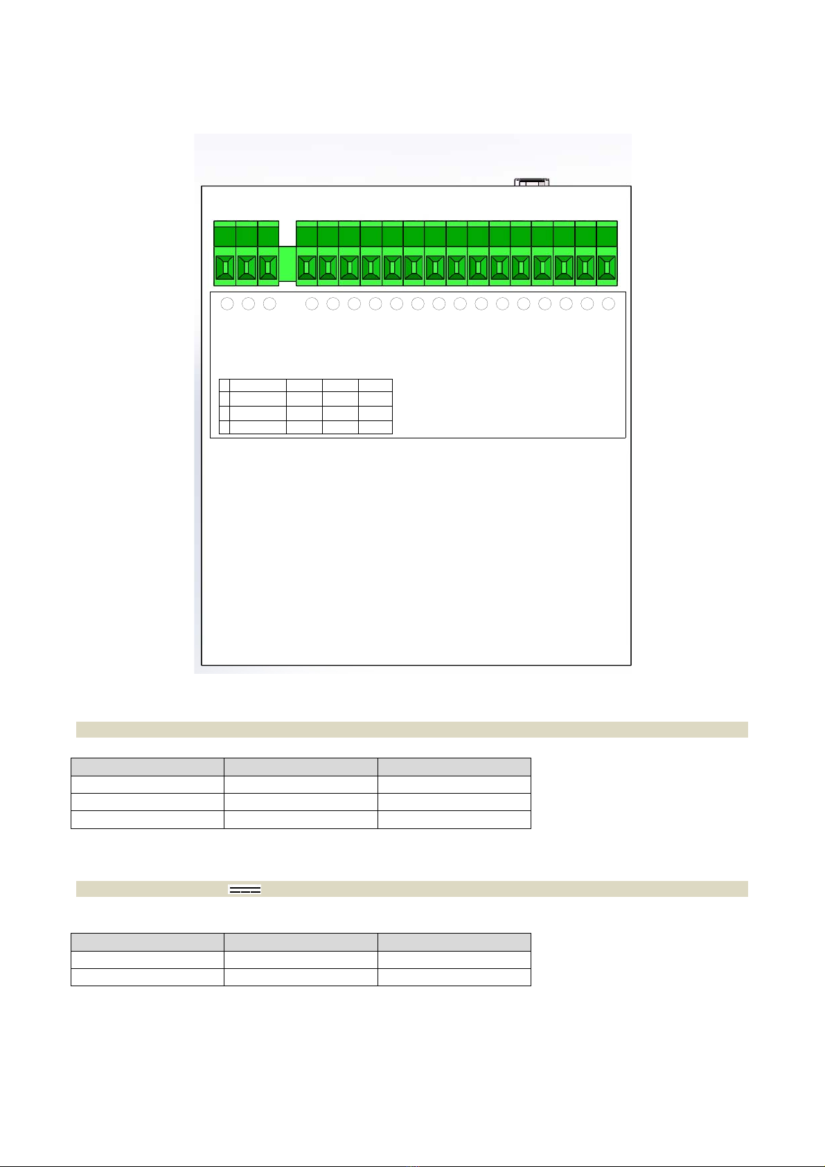
3.6 Connection to power supply (side B)
3.6.1 Version 110÷230V~ 24-48V~
INDICATIONFUNCTIONTERMINAL
NNeutral2
LLine1
EGround3
Connecttheinstrument’ssafetygroundterminaltothesystem’sgroundbarthroughflexiblecable.
3.6.2 Version 12÷24V
INDICATIONFUNCTIONTERMINAL
++12÷241
‐02
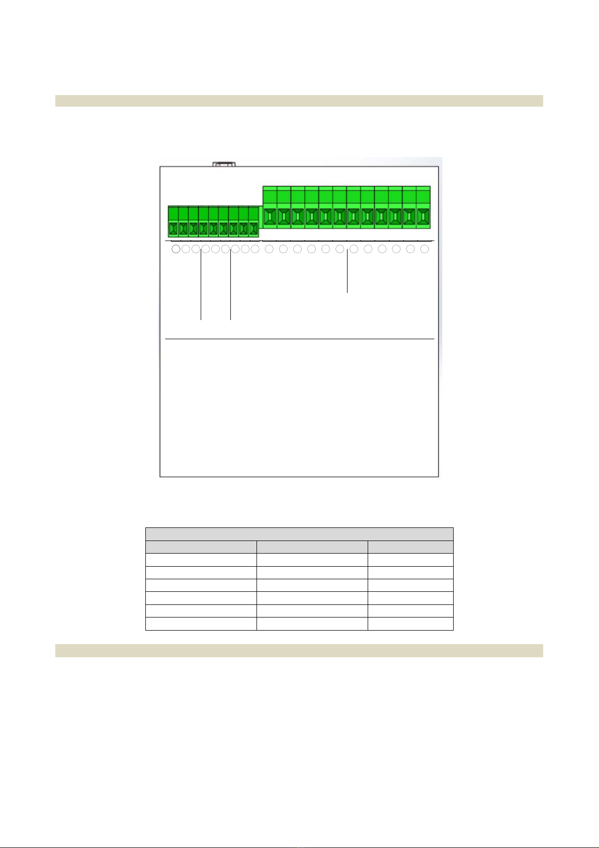
1 2 3 4 5 6 7 8 9 10 11 12 13 14 15 16 17 18
OUT 1
OUT 4
OUT 2
OUT 1
OUT 2
OUT 4
OUT 3
OUT 3
G SAFETY OUT
V SAFETY OUT
OUT 5
OUT 5
INP 2
INP 1
C INP
100-240VAC
124VAC 48VAC
LL
NN
EE
2
3
24VDC
-
+L
E
N
1710‐PT060PNERev.0Page17of57
3.7 Connection of load cells (side A)
Thecablecomingfromtheloadcellsorjunctionboxmustbeconnectedtotheterminalslocatedontherearofthe
instrumentandcalledLOADCELL1.
Connectionbetweentheloadcellandtheinstrumentmustbecarriedoutwithashieldedcable.Thecable’sshield
mustbeconnectedtotheground.
Connectionmusttakeplacerespectingthecolourcodeindicatedontheloadcells.
T060foreseesthestandardconnectionof6‐wireloadcells.Incaseofconnectionof4‐wireloadcells,connectthe
referencewirestotherelativepolaritiesofthepowersupplycables.
MAKESURETHECONNECTIONCABLEBETWEENLOADCELLSANDINSTRUMENTISDUCTEDINTROUGHSSEPARATE
FROMTHOSEOFPOWERLINES,INORDERTOAVOIDCOUPLINGTHATMAYPREJUDICETHEMEASUREMENT
ACCURACY.
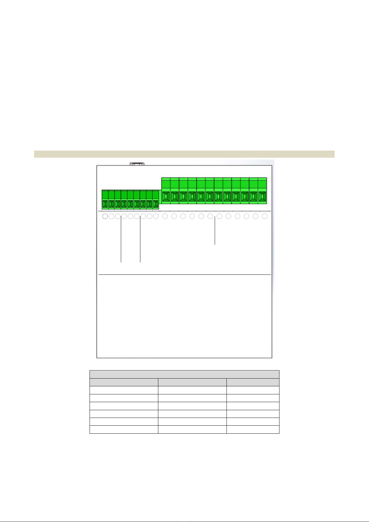
3.7.1 Connection of load cells 1
LC1
INDICATIONFUNCTION TERMINAL
+A+Excitation 39
‐A‐Excitation 38
+S+Signal37
‐S‐Signal 36
+R+Reference 35
‐R‐Reference 34
3128 29 30
-S
+R
-R
3432 33
+S
3635 37
-A
+A
3938
-R
+R
-S
+S
-A
+A
LOAD CELL 2 LOAD CELL 1
232019 2221 2524 2726
SGND 3
IOUT+
VOUT+
SGND 2
-RS485
+RS485
SGND 1
-RS485/RX
+RS485/TX
SERIAL
OUT 1
SERIAL
OUT 2
ANALOG
OUTPUT
OPTO OPTO
1710‐PT060PNERev.0Page18of57
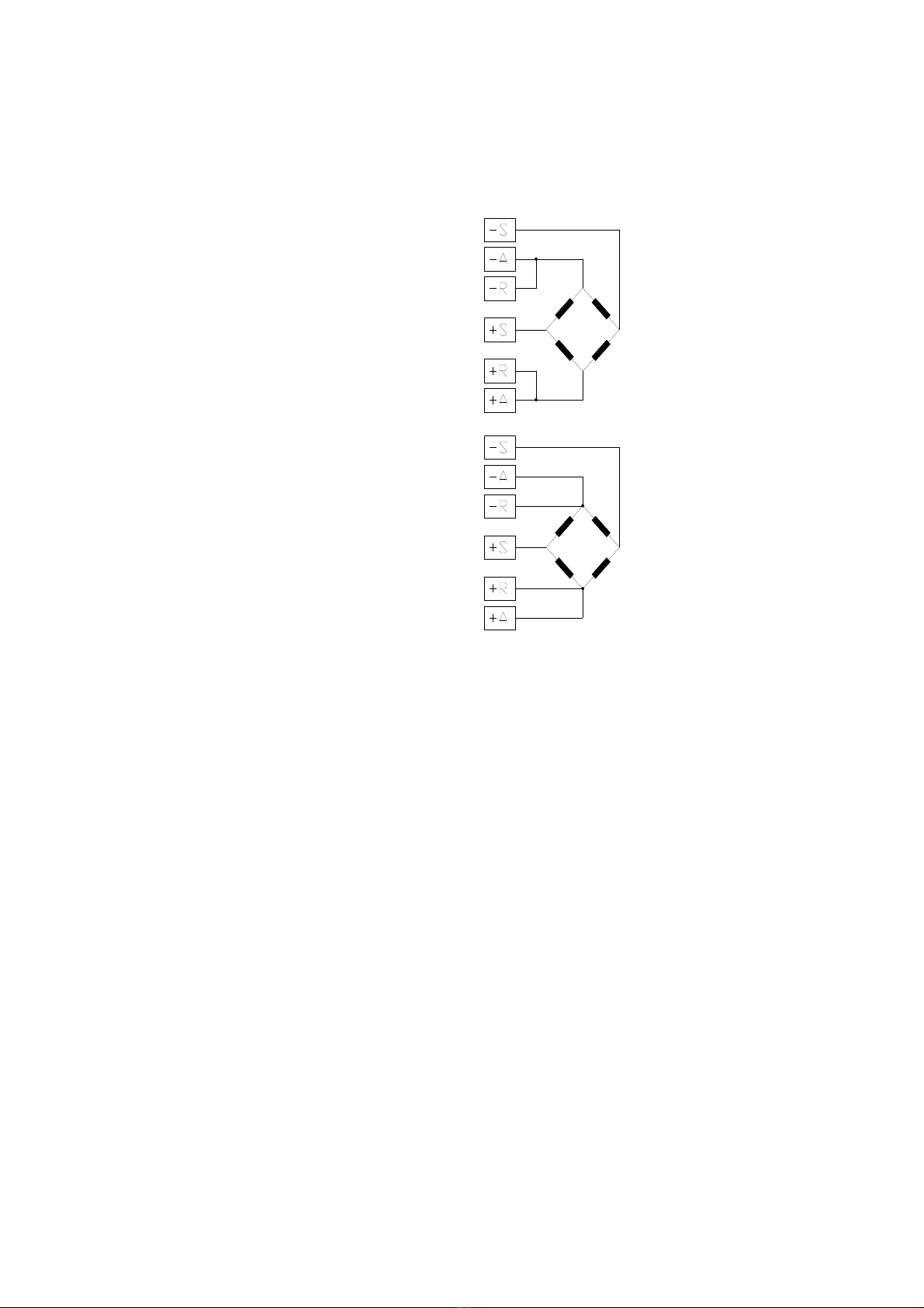
Incaseof4‐wireconnection,short‐circuittheterminals–Excitationwith‐Referenceand+Excitationwith+
Reference.
CONNECTIONWITH4‐WIRELOADCELLS
CONNECTIONWITH6‐WIRELOADCELLS
1710‐PT060PNERev.0Page19of57
3.7.2 Connection of load cells 2 input
T060Eforeseesanoptionalsecondloadcellsinput.Theconsiderationsmadeforthemainchannelalsoapplyforthe
optionalinputchannel.
LC2
INDICATIONFUNCTION TERMINAL
+A+Excitation 33
‐A‐Excitation 32
+S+Signal 31
‐S‐Signal 30
+R+Reference 29
‐R‐Reference 28
3128 29 30
-S
+R
-R
3432 33
+S
3635 37
-A
+A
3938
-R
+R
-S
+S
-A
+A
LOAD CELL 2 LOAD CELL 1
232019 2221 2524 2726
SGND 3
IOUT+
VOUT+
SGND 2
-RS485
+RS485
SGND 1
-RS485/RX
+RS485/TX
SERIAL
OUT 1
SERIAL
OUT 2
ANALOG
OUTPUT
OPTO OPTO

1710‐PT060PNERev.0Page20of57
3.7.3 Wiring example (single weighing system)
Inthecaseofplantconsistsofasingleweighingsystemwithoneormorecellsconnectedinparallelthewiringmust
bemadeonchannel1(seediagramasanexample)
Exampleofasystemconsistingofasingleweighingsystemwithonlytwoloadcellsinparallel
Table of contents
Other Ados Transmitter manuals


Popular Transmitter manuals by other brands

Dwyer Instruments
Dwyer Instruments Series CDTV Specifications-installation and operating instructions

diagral
diagral TT385 Installation and user guide

ASCOM
ASCOM TELECARE WP - BROCHURE 1 brochure

Dwyer Instruments
Dwyer Instruments 629 Series Installation and operating instructions

Acromag
Acromag TT339-0700 user manual

Erone
Erone 028A S2TR2681E2 manual


Worldcast Systems
Worldcast Systems ECRESO FM 750W quick start guide

Sony
Sony WRT-808A Service manual

Honeywell
Honeywell Satellite XT Guide to operations

BWI Eagle
BWI Eagle AIR-EAGLE XLT manual

Ascon tecnologic
Ascon tecnologic ATT1 Engineering manual

BWI Eagle
BWI Eagle AIR-EAGLE XLT Product information bulletin