ADREL ALT-USB User manual


2
Paramaters
Method of altitude measurement: measurement of pressure changes
Measuring Range 0- 5500 m
Resolution 0.2 m (for measurements < 25 meas. / sec )
1 m (for measurements 25 i 50 meas. / sec)
Accuracy: 1 % (accuracy of measuring the difference of altitude)
Supply Voltage: 3,3V to 6V
Current consumption: 5,9 mA
Sampling: 1 ÷ 5 sec / measurement
10 measurements / sec
15 measurements / sec
25 measurements / sec
50 measurements / sec
Max measurement time: 1 - 5h (for 1 ÷ 5 sec / measurement)
400 sec (for 10 measurements / sec )
260 sec (for 15 measurements / sec )
160 sec (for 25 measurements / sec )
80 sec (for 50 measurements / sec )
(total of 4000 measurements)
Measurement triggering: Set in the range of 2 – 200 m
Measurement end: Start level + 7m . Then 32 additional measurements are
taken
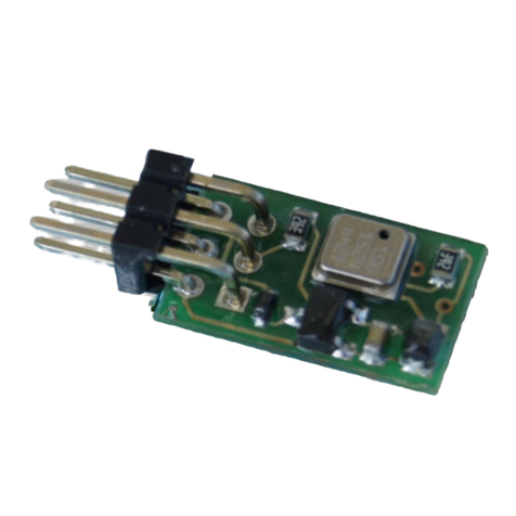
Dimensions: 9,5 x 24 x 7 mm (with connector)
Weight: 1,2 g ( without battery)
Recommended battery: LiPo 20mAh – weight 0,8g
LiPo 50mAh – weight 2g
Battery life for LiPo 20mAh – 3 hours
for LiPo 50mAh – 8 hours
Serial number: Unique entered permanently
Number of contestant: Input form computer
Connection with computer: USB

3
1. Introduction
In accordance with the FAI recommendations, the measurement of altitude in the categories S1
and S5 is to be measured electronically with the use of altimeters. According to these guidelines
altimeter has been developed, which in addition to measuring the maximum altitude, stores
measurement results for the entire flight. Its parameters were adjusted to the recommendations of
the FAI. Altimeter’s size (9.5 x 24 x 7) and weight (1.2 g) allow for its inclusion in all types of
space models. Altimeter may also prove useful when setting F1B model category (eg, choice of
propeller).
2.
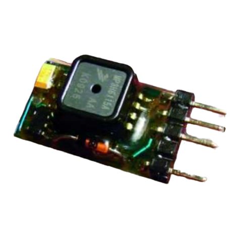
Overview of altimeter
In the described altimeter height measurement is made
on the basis of pressure changes depending on altitude.
Measuring sensor is an electronic system, which measures
the absolute pressure. This sensor is factory calibrated. In
the program, which reads data from altimeter, follows the
conversion of pressure to altitude based on the formula,
which takes into account the current pressure, pressure
changes, temperature, vertical temperature gradient, change
of the density of the atmosphere, depending on altitude..
Model Altimeter AL-01 is used for measuring the height
of the model and the analysis of the flight. Measurements are
stored in nonvolatile memory so they are saved when device
is disconnected from power. Frequency of measurement is set
in the range of 50 measurements per second to 1
measurement every 5 seconds
The readout of the altimeter’s measurements and
parameters is possible when cable is connected to the USB
connector on your computer. The chart shows the entire
flight of a rocket. The graph can be zoomed. For the purposes of competitions altimeter is able to
store the starting numbers of competitors. In addition, each altimeter has a recorded permanent
unique serial number. For archiving the results of
competitions, the measurements can be saved to
disk and retrieved any time.
Adapter - Charger used to connect the altimeter to
a computer using a standard USB cable with the
tip of a type B.
Adapter has a built-
in complete control
system of battery
recharge (single-cell
Li-Pol).
3. Some theory
With the increase in altitude at which it measurement shall be taken the amount column of
the atmosphere decreases, as well as the pressure measured. Pressure changes with altitude within
the first 2000m above the sea are fast - with an increase of altitude about 8m atmospheric pressure
decreases about 1 hPa (see further - bar degree). As a result, measurements made at the same point
and at the same time at different heights, give different pressure values. In addition the changes in
pressure at the same point will be affected by the changes in air temperature.

4
4. Drivers installing
Please install on the PC the USB drivers. The drivers can be downloaded from
www.adrel.com.pl/download - file Altimetr_Program.zip and unzip tem to any folder.
For versions lower than programs 07.2010, you must copy the files from the folder
…/Sterowniki_Builder/ to folder …/windows/system32. They are files: “tee35.bpl” and
“vcl35.bpl”. For versions of 7.2010 and above there is no need to copy these files.
Then connect the altimeter to the computer via
adapter or cable with a 5-pin tip (described above).
For the connection additional hubs can not be used.
Altimeter must be connected via a USB cable AB
type with plugs directly into the computer. Windows
automatically detects the connected device. On the
screen Found New Hardware Wizard will appear.
Select "Not this time" and press "Next".
Then select "Install from a list or specific
location" and press "Next".
Now, select "Include this location in search" and
press "Browse".
Find the folder where you previously unpacked the
downloaded drivers. Select the directory of the
driver, depending on the system:

5
/raw - Windows XP and 2000
/w2k - only Windows 2000
/xpvista7 - Windows XP/Vista/7 x 32
/vista64 - Windows Vista x 64
And press ‘OK’
This brings up a warning message. Ignore it, or
press "Continue Anyway".
The driver will be installed. At the end choose
"Finish".
Then we need to check the COM port number at which the driver has been installed. Then, we
choose in turn:
Start -> Control Panel -> System or
Start -> Control Panel -> Performance and Maintenance -> System
His brings up a window "System Properties". Now select the "Hardware" and press "Device
Manager". Click mark '+' At the label "Ports (COM & LPT)". You should receive a description of
the "Virtual Communications Port (COM ...). This is the
port number that we need to set in the handler of the
altimeter.

6
Vista x 64
Vista x64 does not accept unauthorized kernel-mode drivers. To use AVR-CDC on 64bit
machine, you have to turn the "Driver Signature Enforcement" off by pressing the F8 function key
during system boot up.
"Driver Signature Enforcement Overrider" signs the driver as a Tested river and activates a test
mode so you can load it without a real Signature. You can find a more detailed description on the
download page of the override http://www.ngohq.com/home.php?page=dseo
USAGE
=====
To install the driver:
1. Download the "Driver Signature Enforcement Overrider".
http://www.ngohq.com/home.php?page=dseo
2. Start the DSEO (no installation is needed).
3. Choose "Sign a System File", click the "next" button and sign
lowcdc.inf.
4. Choose "Sign a System File" again, click the "next" button and sign
lowcdc.sys.
5. Choose "Enable Testmode" and click the "next" button.
6. Restart your computer.
5. The maintenance program of the altimeter
Before first use of the altimeter set its parameters. To do this, connect the altimeter to the
computer using a USB cable (as described above) and call the handler Altimetr.exe.
Then press the "Settings". "Setup" window appears.
You need to set the communication port number, which we checked with the driver installation. If
after you select the port you will receive an error message, then make sure you have selected the
correct port and that the cord is inserted into your computer and you have installed the USB driver.
Then, in the following order, input:
- Measuring altitude start
- Current temperature
- Select the frequency of measurements
- Set the way the reset altimeter (described below)
- Number of the competitor
When you press "Save", entered settings will be saved to the altimeter. Exit
without saving the occurs after the closing of the window (click on X).
These settings are remembered by the altimeter, even after power is switched
off. Just a single programming is enough.
1. Setting " Measurement Start Height "
Measurements start after reaching a height set in the parameter "Start Height
Trigger" The optimum height is about 20 - 30 meters. Altimeter records
measurements from the last three seconds before detection of measurement
start level. If you set the start level too low (below 7 meters), the
measurements could be started already at the starting position (fluctuations in
atmospheric pressure are sufficient to start the measurement.) Then the height measurement
is performed until the memory is full (the level of the landing is not checked - normally set
to 7 meters). If a competitor delays the start, the whole flight may not be registered.

7
2. Sampling Frequency
Acc. FAI rules, the measurement must be performed at least 10 times per second. Altimeter
ALT-USB has the ability to set the measurement frequency. It is best to set
15 measurements per second. This ensures fast measurement with accuracy. Setting
a higher frequency of measurements reduces the measurement resolution (to 1 meter)
3. Setting "manual reset"
Altimeter can be reset in two ways: by using software or by altimeter’s contact closure.
During the event, set the lock of manual reset (parameter “manual reset "set to" No ").
A competitor himself can not reset the altimeter.
4. Calibration of temperature.
During the conversion of the amount of pressure to height the air temperature is taken into
account. Altimeter has a built-in temperature sensor. In altimeter’s settings this sensor can
be calibrated. Before the calibration altimeter be should put in place ensuring the ambient
temperature for about 5 minutes (not connected to power). Then connect to your computer
and enter the current temperature settings (field Setup -> “Calibration of the Temp.”).
5. Number of competitors
In the "Competitor No." enter the number.
Before measuring, you must reset the altimeter. This can be done through the program,
pressing the button "Reset". After an additional confirmation, the message of altimeter reset
appears. You can now disconnect it from the computer and connect the battery. Proper reset is
signaled by a single, short-blinking LED. No reset is signaled by 3 blinks of the diode. Altimeter
can also be reset by shorting the pins. To make this possible, you must first set the "Manual Reset"
to 'Yes'. If it is set to 'No', then reset is only possible through the program. Locking this reset is
required during the competitions
6. Assembly of altimeter in the model
It is very important how to install the altimeter in the model. In particular, this applies to
measurements on competitions. The chamber, in which the altimeter is assembled, can not be tight.
There must be holes, allowing the pressure around the altimeter to equalize atmospheric pressure.
Where should we locate the altimetr?
If you plan to put altimetru the rocket to be taken into account that the altimeter is a device
which measures changes in pressure. Therefore, should not be placed in the immediate vicinity
altimetru engine. Altimeter must be separated from direct gas engine. Ignition, which ejects the
tape brake can significantly distort the measurement results as well as destroy the same altimeter
(gases are very corrosive.) Therefore, you should always use the separating pistons. Must be
maintained order: engine, brake piston with tape or other separator, container from the altimeter.
Ventilation holes
For rockets S1 do not have ventilation holes (if the rocket is not hermetic)
For rockets S1 to be done two or three holes with a diameter of 0,3 mm – 0,4mm – (if the rocket is
hermetic)
For rockets S5 to be done two or three holes with a diameter of 0,4 mm – 0,5mm
In models of gliders, airplanes, just altimeter is placed inside the hull model. In models that do not
have a closed hull, perform a separate container where you put altimeter.

8
Connecting the battery
Please pay attention when connecting the battery, the battery connector pins should be parallel
to altimeter’s contacts. Inserting the plug under angle does not provide adequate contact and the
battery can be detached from the altimeter. When connecting clear perceptible resistance should be
felt.
After connecting the battery serial number is displayed, then the reset state is signaled by - the
LED should blink single flashes. Three flashes indicate that the altimeter is not cleared and that it
can be reset manually. Four flashes mean that the altimeter is not cleared and that it can not be
reset manually. It is possible to reset only by the computer.
Before inserting into the enclosure, you should make sure that the LED is blinking single flashes
(altimeter alarm reset). Be careful with any assembly work, so as not to produce negative pressure
in the chamber of the altimeter. Particular attention should be paid when removing the head of
rockets. We can create a vacuum in the chamber of the altimeter and thus start the measurement.
The altimeter rejects measurements of pressure changes that last less than 2 seconds. However,
before re-assembly of the model, you need to make sure that the altimeter is reset, and possibly
reset it. Measurements start after about 3 minutes from the power connection.
7. Altitude measurement.
Altimeter can be powered from any battery with a voltage of 3.3 V to 6V. Altimeter’s
contacts have 2mm spacing, so be sure to use the appropriate plug. At the end of this manual there
are addresses of online shops where you can
buy these connectors, and the names of these
connectors. The figure shows the power
connection. Altimeter
is protected against
reverse connection of
power supply.
After connecting the power, LED blink once or three times. This is a state reset. After a time of
2 seconds the LED is blinking, then displays the serial number of the altimeter. You can stop the
display of the short connection of the reset pins.
Altimeter can be reset without a computer (as far as we indicated in the settings "Manual reset '
Yes'). We should wait until the LED will blink 3 times (if altimeter is not reset) and then short for
a moment two free contacts of the connector (marked in the figure as data contacts or reset). LED
will blink with single flashes.
Altimeter is ready for measurement. Reset by shorting the contacts does not erase the previous
measurement. The start of the measurement (indicated by 2 blinks) deletes the previous data.
Measurements are taken 3 minutes after connecting the battery or reset. They are not stored in
nonvolatile memory only in the so-called instantaneous. Only after the detection of previously
programmed measurement triggering value, the last 32 and current measurements are saved.
altitude measured before the launch is regarded as a reference, or the amount of '0 '. Start of
measurement (ie, exceeding the pre-programmed "altitude of the start of measurement") is signaled
by double blink of diode. Current measurements are saved in memory. After a minimum of
2 seconds after the triggering of measurement altimeter verifies if the model is dropping. If it
reached the altitude of less than 7m, and the model will not get lower, 32 more measurements will

9
be taken, and the cycle is completed. The end is signaled by three blinks of LED (as in the absence
of zeroing). You can disconnect the battery and connect the altimeter to the computer to read data.
If the end of the measurements was not detected automatically, you must short the contacts for
a while (like the return to zero). The measurement is completed
8. Reading of measurements.
After the flight, check if it has been measured. Start of measurement is indicated by two blinks
of the diode. The end of the measurement (detection of land level or the end of memory) is
indicated by a three blinks of LED. However, if after the flight the LED blinks twice, it means that
level of the landing has not been detected -
but the measurements were made. You can
disconnect the battery – until this time
measurements were recorded in the
memory. When connected to a computer,
the altimeter’s LED should blink three or
four flashes (this depends on the parameter
settings "reset manually - as described
above). This means that the measurement
was registered. After pressing the "Read
altimeter" measurements will be read and
displayed on the screen.
On the right side maximum and
minimum altitude will be displayed. In the
"contestant" window the number of
competitor and the serial number will be
displayed.
Read data can be saved on your computer HDD by pressing "Save" in the panel "Drive - Read /
write. Such recorded data can be played back at any time. Altimeter does not need to be connected.
The program can read the current temperature measured by the altimeter.
The graph can be zoomed. Use your mouse to mark the
interesting part of the chart. During
zooming it is important to mark from left
to right. Any selection from right to left
returns to the view
of the entire chart.
Below are the charts
after the increase.
Graphs of the flight can be compared with each other. To do
this, read data from altimeter or disk, and then click
"Compare". This brings up a file selection window. Please
select a file with data to compare and click 'Open'. An
additional chart appears on the screen. Speed chart and
comparisons can be switched off in the menu tab "Charts"
Temperature correction
Altimeter calculated height assuming the temperature, that was measured by the altimeter.
However, in many cases, the temperature may differ significantly from the actual value. It is
enough that before installation, altimeter is exposed to sunlight or a competitor will keep it in his

10
hand. The measured temperature may then vary up to several degrees C. The difference in
calculating the amount of approximately 0.3% per degree C. For example, height of 355.5 meters
at 24 C, after correction for 20 C temperature is 350.7 (the difference of 4,8 meters).
In the handling software of the altimeter (from version 5.2010), temperature correction is possible.
After typing in the "Temperature" field of the new value and pressing "Enter" key, measurements
will be re-converted and displayed. It is recommended that the start cards had additional line,
which keeps the ambient temperature.
Filter
If the altimeter was not properly mounted and subjected to a direct effect of air flow, it also
works on its dynamic pressure, which distorts the measurements. Also wind gusts interfere. The
graph can be seen as a clear "pin", which differ substantially from the correct chart. You can then
use a filter that removes these erroneous measurements. The measurements are filtered multi-
stages. First, discard the "pins". He then calculated the average and again rejected the
measurements are wrong, but taking into account this average. The result is as smooth graph.
The data read from the altimeter, or read from the disk can be filtered in using Filter button on
the left side of the screen.
Data for comparison, can be filtered using the button at the Filter, which is under the
"Compare" button.
After filtration, two graphs are drawn - before and after filtration. By clicking the left mouse
button on the chart, you can delete it. When you change the parameter settings of the filter can
filter out the data again, no need in re-load measurements.
Filter parameter can be set settings tab in the Filter
The "altimeter" has its own instructions. Is displayed when you press "Help"
9. USB Adapter
As described earlier, to connect the altimeter to a computer you need a special adapter. There
are offered two types of adapters: with charger and without t charger. You can also try to make
cable for connecting the altimeter yourself. To do this in a typical
USB cables cut off one plug (leave the plug connected to a
computer) and isolate the wire length of approximately 1.5 cm.
Then color-coded wires as in the photo should be soldered (or
tightened) to the appropriate connector pins. Please note that the
pin spacing is 2mm. Below are listed the addresses
of shops and types of connectors needed
for the implementation of the cable. Free contact must be filled so
that one could not connect the altimeter in the opposite way.
http://www.tme.eu/pl/katalog/?art=ZL265-5SG#id_category%3D100035%26
zl265-5sg connector for soldering
http://www.maritex.com.pl/pl/shop/products/ggid/9326
PBMS05S-LF connector for soldering
BLMS05 Crimp Terminal Housing, 5-pins, single row – clamped connectors
BLMT Metal terminal, for BLMS and BLMD type housings

11
10. Charging the battery
Using adapter charger you can recharge rechargeable lithium-polymer (Pol Lid) batteries.
There are available pin connectors where the battery should be connected. Charging is indicated by
LED. When the LED is off charging is finished. As a source
for supplying the charger you can use any computer,
connecting the adapter to the USB connector. Computers even
when switched off supply this voltage. Now mobile phones
have chargers which have the USB connector. You can use
them as power source.
Battery connector
www.tme.pl
NXG-03 plug shield
NXG-T contact
www.Maritex.com.pl Crimp Terminal » Crimp with pitch 2.00mm
HS-03 plug shield
HST-LF contact
CAUTION!! In the connector shield cut off two small blocking tongue
that are placed on both sides, so that the plug is not stuck in the charger-
adapter connector.
Table of contents
Other ADREL Measuring Instrument manuals
Popular Measuring Instrument manuals by other brands

GESTRA
GESTRA LRG 16-40 Original Installation Instructions
PCB Piezotronics
PCB Piezotronics 3501B1260KG Installation and operating manual
Bante Instruments
Bante Instruments TB200 instruction manual
Apera Instruments
Apera Instruments 800 Series instruction manual
Endress+Hauser
Endress+Hauser Proline Promag D 400 HART operating instructions

Stocks AG
Stocks AG MM 117A Installation, Calibration and Operation
