STOCKS AG –MICROMETER APPLICATOR CONTROL SYSTEM
7
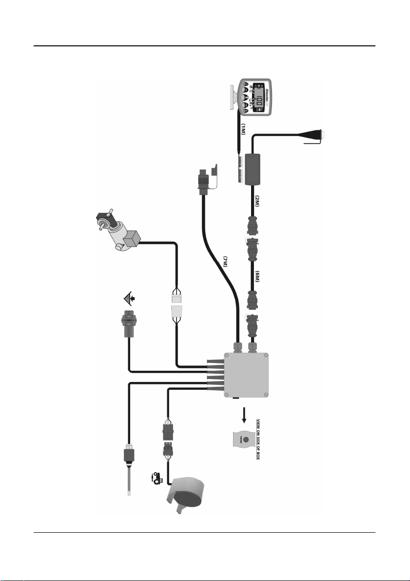
2.2 The Head Unit
Confirm with the operator on where to mount the head unit in the cab. It must
not restrict the view out of the cab, nor impede the use of the controls. The
head unit is fitted with a 1-metre flying lead terminating with an 8/10-way IDC
type connector, ready for connection into the "Terminator" junction box.
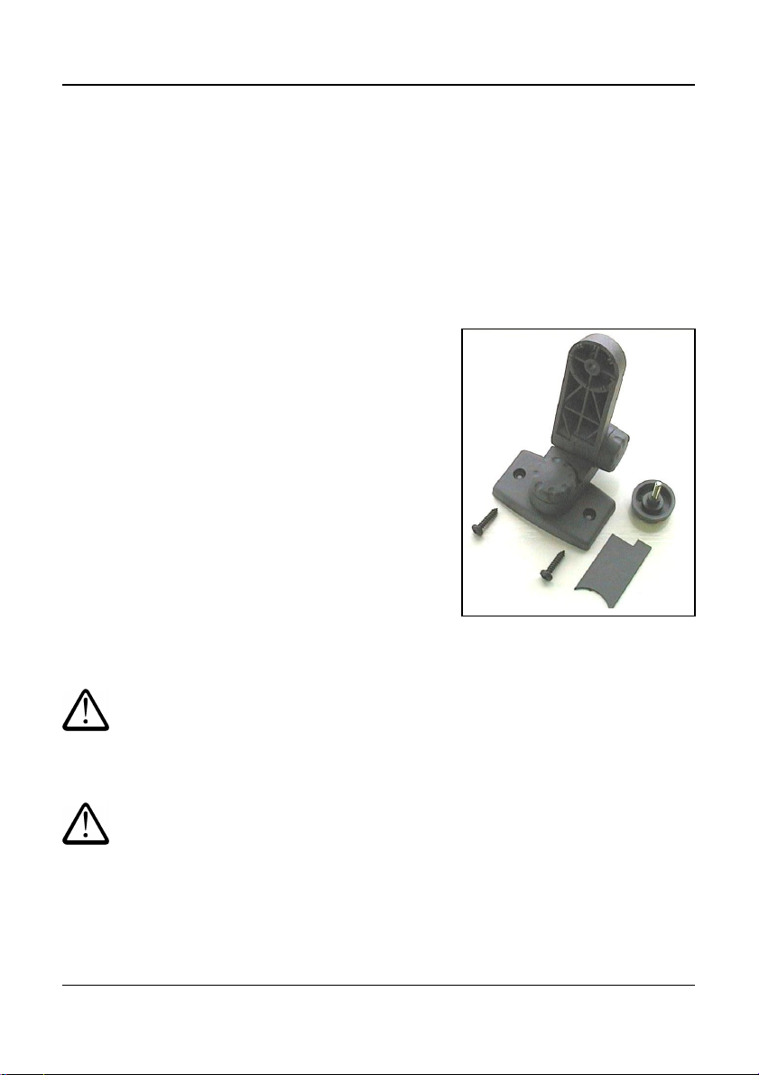
The head unit is supplied with mounting kit ref: TJ235 comprising the following
parts (fig. 2):
1 Long Bracket
1 Short Bracket
3 Clamping Knobs
1 Cover Plate
1 Mounting Plate
2 Self Tapping Screws
1. Snap the cover plate into the recess of the
long bracket (it only fits one way).
2. The instrument mount is designed to offer
maximum flexibility in positioning the
head unit, either from the right hand side
of the cab, from the dashboard or from an
overhead position.
Assemble the two brackets, and mounting
plate with clamping knobs, and attach to
the head unit.
NOTE: Either the long or short bracket can be
attached to the head unit, whichever gives
the most suitable orientation.
Having established the orientation for the
bracket, fix the mounting plate to the cab
with the self-tapping screws provided.
Do not drill into a ROPS or FOPS frame.
If you are fixing the mounting plate to plastic e.g. the dashboard or other cab
moulding, it is recommended to use M4 screws with mudwing washers to
strengthen the mounting point.
Do not attempt to adjust the mounting bracket assembly without first
slackening off the clamping knobs sufficiently. You will only succeed in
damaging the bracket otherwise.
Figure 2 : Head Unit Mounting Kit