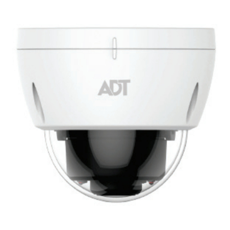
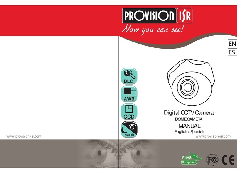
ADT Pulse MDC835 User manual

ADT PulseInteractiveSolutions
MDC835
Mini DomeCamera
InstallationGuide

Chapter 1 Introduction
Table OfContents
CHAPTER1INTRODUCTION..............................................................................1
Overview........................................................................................................1
Physical Details..............................................................................................2
Package Contents..........................................................................................4
CHAPTER2BASICSETUP..................................................................................5
Installation......................................................................................................5
CHAPTER3CEILINGMOUNTING.......................................................................5
Ceiling Mounting Installation...........................................................................5
CHAPTER4ADTPULSEENROLLMENT.............................................................9
Wired Connection tothe GatewayUsing the PulsePortal...............................9
Using WPS withPINtoEnroll the Camera....................................................12
If the CameraContinuallyGoesOffline.........................................................16
APPENDIXASPECIFICATIONS........................................................................17
MDC835 IPCamera.....................................................................................17
Regulatory Approvals...................................................................................17
Copyright 2016.All RightsReserved.
DocumentVersion:1.0
All trademarksandtradenamesarethepropertiesoftheirrespectiveowners.

1
Chapter 1
Introduction
This Chapter provides details of the IP Camera
features, components and capabilities.
Overview
Thiswireless 802.11n weather-resistantIPCamera, whichcomeswiththe IP66
rated housing, hasaF1.8large apertureLens,SONYhigh sensitivityimaging
sensorand high powerIRLEDillumination, enabling it todisplayhigh quality
colorful image in low lightcondition and coverthedistanceup to20 meters atnight.
Thisdeviceisalsoan all-in-one camerathathasautomaticday-night switching,
built-in heaterand Mechanical Pan/Tilt/Rotateorientation adjustment.
The cameraisintended forusein ADT Pulse.
Features
•Lens Support. The IPCamerahasthe built-in F1.8LenswithSONYExmor
high sensitivity3.75 mpixel image sensor.
•Dual Video Support.The IPCamerasupportsH.264 and MJEPGvideo
compression.
•IR LEDs Support. The built-in two infrared LEDscan provide illumination
forup to20 meters.
•Built-in Heater. The built-in Heaterensuresthatthe camerawill continue
tooperateeven in extremelycold outdoorclimates. Theheaterturnson when
the temperaturefallsbelow 26.6°F(-3°C).
Wireless Features
1

Chapter 1 Introduction
2
•Supports 802.11n Wireless Standard. The 802.11n standard
providesforbackwardcompatibilitywiththe 802.11b/gwireless network.
•Supports WPS. Wi-FiProtected Setup (WPS) can simplifythe processof
connecting the IPCameratothe wireless network bypin code mode via ADT
pulse.
•Wired and Wireless Support.The IPCameracan be connected tothe
Pulsenetwork wirelessly. Itcan alsobe hardwired tothenetwork.


Chapter1Introduction
2
PhysicalDetails
Front/RearPanel
Figure1: Front/RearPanel
IRLEDs Theyareused toprovide illumination fornight time.Please
ensurethat the two IRLEDscan be revealed in the
transparent Dome.
Light Sensor Thisisahardwaresensortodetect lux.Pleaseensurethat
the light sensorcan be revealed in the transparent Dome.
Lens No physical adjustment isrequired forthe lens.Please
ensurethat the lenscoverremainsclean.
LANport UseastandardEthernet cable (not included)toconnect
the LANportofthe supplied cable and the PulseGateway
orTSBasepanel.
Note:
lPlugging in the Ethernet cable will disable the wireless
interface.Onlyone interfacecan be activeat anytime.
lThe Ethernetcable should onlybe connected or
disconnected when the cameraispowered OFF.
Attaching ordetaching the Ethernet cable while the
cameraispowered on doesNOT switchthe interface
between wired and wireless.

Chapter1Introduction
3
PowerInterface Connect the two wiresofthe supplied cable tothe terminal
adapter. Do not usethe otherterminal adapters; doing so
maydamage the camera.
PowerIndicator
(Green, Amber,
Blue)
On (Green) -Poweron.
Off –Nopower.
Blinking (Green) -The LEDwill blinkduring start up or
wireless connection isunderassociation.
On(Blue) -Network connection isavailable (wired or
wireless).
On(Amber) -If the LEDison for5secondsand then turns
off,the WPSfunction hasfailed; orthe heaterisactive.
Blinking (Amber) –The WPSfunction isactive.
Note: If thedataisbeing transmitted via WiFi/LAN,The
colorof the LEDisblue in the mean time.
Reset/WPS/ImageFlipButton
Figure2: WPS/Reset/Image Flip Button

Chapter1Introduction
4
WPS/Reset/
Image Flip Button
The button servesthree functionson the camera.
lWPS Pin Code Mode. When pressed and held for5
secondsduring the Pulseenrollment process,the
cameracreatesan encryption-secured wireless
connection.
lReset. When pressed and held over15 seconds,the
camerarebootsand the settingsarerestored todefault
values.
lImage Rotation. When the cameraconnected toADT
Pulse, the image will turn180°if you fast-click this
button twice.


Chapter1Introduction
4
Package Contents
The following items areincluded:
1. IPCamerawithpigtail (DC-INand RJ45)
2. Terminal Adapter
3. Wall Mount Screw Package
4. LTool (T10)
5. SpiceConnector

5
Chapter 2
Basic Setup
ThisChapterprovidesdetailsofinstalling and configuring the IP
Camera.
Installation
Figure3: Wired NetworkConnection
1. Make the Connection
Using a Wired Connection
If you are using a wired connection to the MDC835, connect
a standard Ethernet cable (not included) to the LAN port
of the supplied cable of the camera and the Pulse Gateway
or Total Security (TS) Base panel.
Using a Wireless Connection
The wireless (WPS) connection between the camera and the
Pulse Gateway or Total Security (TS) Base panel is
performed during the Pulse enrollment. See the following
section for more details.
2

Chapter2BasicSetup
6
NOTE
NOTE: The Wireless and LANinterfacescannot be used
simultaneously. Making awired LANconnection disablesthe
wireless interface.
2. Power Up
a. Run the AC Wire to the spice connector.
b. Screw the red wire onto the positive(+) terminal of the
terminal adapter.
c. Screw the black wire onto the negative(-) terminal
of the terminal adapter.
d. Plug the terminal adapter into a power outlet.
CAUTION: Onlyusethe terminal adapterprovided. Using a
different adaptermaycausehardwaredamage.
3. Check the LED
The Power LED will turn on briefly, and then start blinking.
It will blink during startup, which will take 60 to 90
seconds. After startup is completed, the Power LED should
remain ON.
4. Enroll the Camera in ADT Pulse
This process is described in the later chapter.
After the enrollment, please check the image orientation.
You may rotate the image 180 degrees by fast-clicking the
WPS/Reset/Image Flip button twice.
5. Mount the Camera
Place the camera in adesired location near apower source.
For mounting on the ceiling with the mounting
plate, see
Chapter 4 for more details.
Mounting Suggestion
To get the best video quality for targets at night, make sure
that the camera s field of view does not include a foreground
object, such as side wall or roof. Once installing on a
ceiling, angle the camera so that a minimal portion of the
wall is visible.

5
Chapter 3
Ceiling Mounting
This Chapter provides details for final ceiling
mounting of the IP Camera
Ceiling MountingInstallation
NOTE
NOTE: Ensure that the camera is configured and
enrolled in ADT Pulse before permanently
mounting it.
1. Locate an unused indoor outlet to plug into the terminal
adapter. The outlet should be located as close as possible
to the location where the camera will be permanently
mounted.
CAUTION: Do notplug in the terminal adapteruntil all the
connectionsarecompleted and the cameraisfullymounted.
2. Identify the location where you would like to mount the
camera. And then drill three holes on the ceiling based on
the mounting template (last page).
3. Remove the sponge from the camera. And then use the L tool
to remove the three screws and the bubble from the camera.
3

Chapter3CeilingMounting
6
Figure 4: Removing the bubble from the Camera
4. If using the anchors, insert them into the mounting holes.
5. Align the three mounting holes of the camera stand with the
three holes and mount the camera stand on the ceiling using
the provided screws.
Figure 5: Ceiling Installation
NOTE
NOTE: It is recommended to route the cable
through the side opening of the mounting base.
6. The camera offers 3-axis adjustments:
lLoosen the tilt adjust screw to adjust the tile angle
(0°~70°).
lAdjust the pan angle (0°~330°) by holdingthe black liner.
lUse the lens to rotate (0°~350°) the camera.
Figure 6: Angle Adjustment

Chapter3CeilingMounting
7
CAUTION: Do not entwine the antenna while
connecting the LVDS cable.
Figure 7: LVDS Cable
7. Attach the bubble to the camera and tighten it using the
three screws.
NOTE
NOTE: You can use the marks for alignmentwhile
attaching the bubble to the camera.
Figure 8: Attaching the Camera

Chapter3CeilingMounting
8
CAUTION: Makesuretotighten up the three screwsin orderto
prevent waterfromthe camera.
CAUTION: Becareful nottoletthe bubble coverthe light
sensorand damage the LVDScable while attaching thebubble
tothe camera.
8. Connect the power cable to the terminal adapter.
lScrew the red wire onto the positive(+) terminal of the
terminal adapter.
lScrew the black wire onto the negative(-) terminal of the
terminal adapter.
9. Plug the terminal adapter into a power outlet.
10. Make sure the IP Camera is firmly fixed on the ceiling.
11. Verify that the camera is active on the wireless network
and is recognized by Pulse.
NOTE
NOTE: It is recommended to let a qualified
technician install the device.

9
Chapter 4
ADT Pulse Enrollment
This section provides instructions for wirelessly
enrolling the MDC835 Camera into the ADT Pulse
network. This process uses the Wi-Fi Protected Setup
(WPS) with PIN method to wirelessly enroll the
Camera to the gateway via the ADT Pulse Portal or TS
Installer App.
Wired ConnectiontotheGatewayUsing thePulsePortal
1. Set up the Camera, as described in the previous chapter.
2. Open a web browser and in the address bar, enter:
https://Portal.ADTPulse.com.
3. Type your Username and Password, and then click the Sign
In button.
4. Click the System tab, and then click the Manage Devices
button.
4

Chapter4ADTPulseEnrollment
10
5. In the Manage Devices Assistant, click Cameras.
6. Click the picture of the MDC835 or select it from the
drop-down list, and then click the Continue button.

Chapter4ADTPulseEnrollment
11
7. Assign the MDC835 a unique Camera Name (usually based on
the location of the camera) in the spaceprovided, and
then type in the camera sMAC ID.
8. Click the Continue button.
9. Ensure that the camera is connected to the device port
of the Gateway using the Ethernet cable. Click Continue.

Chapter4ADTPulseEnrollment
12
10. After the Camera has connected and the button is no
longer grayed out, click Continue.
11. Click Finish. The Pulse enrollment is complete.
12. Disconnect the camera from the Gateway and remove from
power.
13. Install the camera inits finallocation.
Using WPS withPINtoEnroll the Camera
1. Set up the camera, as described in the previous chapter.
2. Launch an Internet browser and log in to the Pulse portal
or TS installer app.
3. Enter the Manage Devices screen using one of these
methods:
lFor the Pulse portal, select the System tab and click
Manage Devices.
lFor the TS installerapp, click the PulseDevices link.
The Manage Devices screen displays.
4. In the Manage Devices screen, click Cameras.
5. Click the Add Using WPS button, located at the bottom of
the screen.
Other manuals for MDC835
1
Table of contents
Other ADT Pulse Security Camera manuals
Popular Security Camera manuals by other brands
GE Security
GE Security CyberDome II Specifications
Super Circuits
Super Circuits PC508-IR2 user manual
Eneo
Eneo ENC-1003L Installation and operating manua
CIS
CIS VISION:elite VCC-F52U25CL Product specification & operational manual
LevelOne
LevelOne FCS-3101 user manual
Digital Watchdog
Digital Watchdog MEGApix DW-MV82WiA user manual
