1Section 61410020L2-5, Issue 361410020L2-5C
Section 61410020L2-5
Issue 3, July 2001
C A U T I O N !
SUBJECT TO ELECTROSTATIC DAMAGE
OR DECREASE IN RELIABILITY.
HANDLING PRECAUTIONS REQUIRED.
CONTENTS
1. GENERAL ......................................................................1
2. INSTALLATION .............................................................2
3. CONFIGURATION .........................................................3
4. TESTING ......................................................................3
5. WARRANTY AND CUSTOMER SERVICE ...................6
FIGURES
Figure 1. DE-4 U-BR1TE II.................................................1
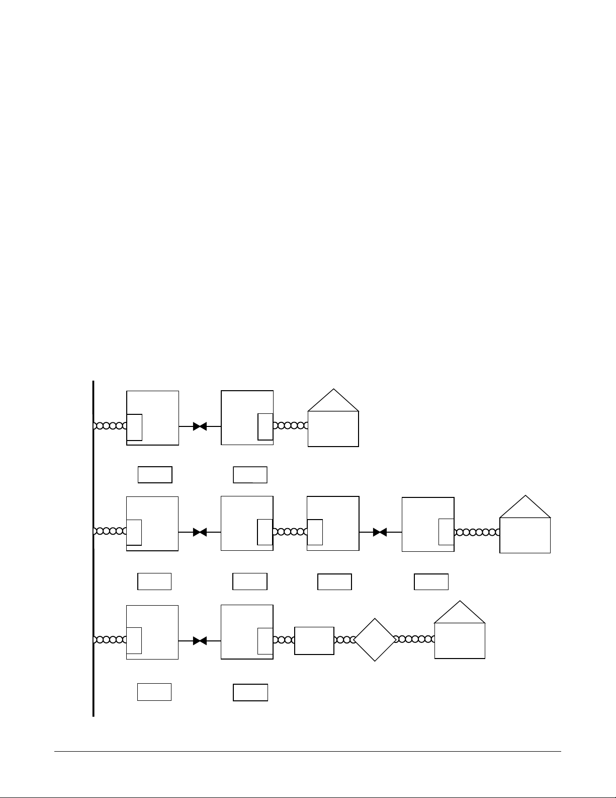
Figure 2. Position Switch Setting at Network Locations ....2
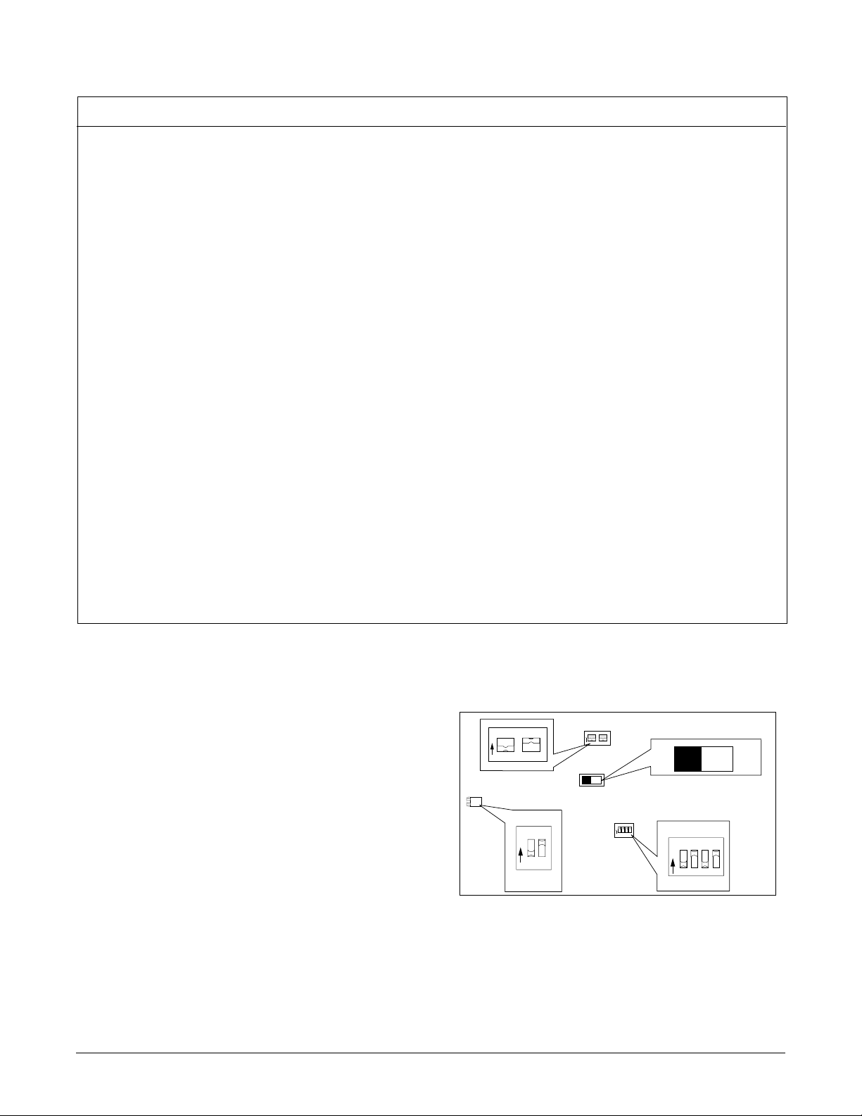
Figure 3. SW1, SW2, and SW6 Labeling ..........................3
Figure 4. Faceplate ............................................................5
TABLES
Table A. Faceplate LED Indicators ....................................3
Table B. SW1, SW2, and SW6 Option Settings ................4
Table C. Rotary Switch Options .........................................5
Table D. Specifications.......................................................7
Model ADTRAN DE-4 U-BR1TE LI
ISDN 2B1Q Interface for
Northern Telecom Channel Banks
Installation and Maintenance
Figure 1. DE-4 U-BR1TE II
Each list of the DE-4 U-BR1TE are interchangeable with
the Northern Telecom ISDN Channel Unit (NT4S10AA)
however, provisioning using the DE-4E Smart Transmit/
ReceiveUnit (STRU) interfaceis not supported. Features
of the DE-4 U-BR1TE L2 and L4 include:
• ISDN 2B1Q interface meets all Layer 1 requirements
as specified in ANSI T1.601-1992.
• Transports ISDN Basic Rate 2B+D information over
T1 facilities in the 3-DS0 format per TR-NWT-000397.
• 18 kft nominal range on mixed gauge wire (42 dB @
40 kHz loop loss, 1300 ΩDC resistance).
• Respond to all Layer 1 maintenance functions.
• Performance monitoring of the Layer 1 facility as
specified in TR-NWT-000397.
• Distinctive metallic DC test signature to identify either
line unit LT or line unit NT mode of operation.
• B1 and B2 addressability at the faceplate for a local
loopback, the NT1, and up to six devices in the
network-to-customer direction.
1. GENERAL
This practice provides installation and maintenance
information for the DE-4 U-BR1TE II L2, part number
1410020L2, and the DE-4 U-BR1TE II w/PWR L4, part
number 1410020L4. Figure 1 is an illustration of the
DE-4 U-BR1TE II.
The DE-4 U-BR1TE II L2 and L4 are line cards designed
to operate with the Northern Telecom DE-3/4/4E and
DE-4E SMART channel banks. Both lists of the DE-4 U-
BR1TE provide an ISDN U-interface allowing
transportation of Basic Rate ISDN (2B+D) over T1
carriers. This allows ISDN service to be extended
beyond the normal servicing range (18 kft) of an ISDN
ready switch. Either list of the DE-4 U-BR1TE 2nd
Generation may be used in the Central Office Terminal
(COT)location andin theRemote Terminal (RT)location.
Each list of the DE-4 U-BR1TE plugs into a single
physical slot but requires up to three consecutive time
slots when configured for 2B+D. Block error rate (BER)
performanceovertheT1 facilityis monitoredandavailable
to the network.
The DE-4 U-BR1TE II w/PWR L4 provides an ISDN 2B1Q
U-interface that will supply 43 mA to span power an
ADTRAN ISDN U-Repeater II or U-Repeater III.
Trademarks: Any brand names and product names included in this document are trademarks, registered
trademarks, or trade names of their respective holders.
LPBKCRTX
LPTX
NT1
AD1
AD6
AD5
AD4
AD3AD2
TEST
B2
B2
PTRN
NORM
1 2
Rx
Tx
DS-0
LOGIC
TSTERR
LPCR
ACT
UBR1TEII
1410020L2
O
N
1
2
O
N
1234
SW5 SW1
SW6
(Only on the L4)
SW2
SW4
SW3