manuals.online logo
Brands
  1. Home
  2. •
  3. Brands
  4. •
  5. ADTRAN
  6. •
  7. Recording Equipment
  8. •
  9. ADTRAN NetVanta 5305 User manual

ADTRAN NetVanta 5305 User manual

Other manuals for NetVanta 5305

7

This manual suits for next models

1

Other ADTRAN Recording Equipment manuals

ADTRAN Network Interface Module T1/FT1 User manual

ADTRAN

ADTRAN Network Interface Module T1/FT1 User manual

ADTRAN SHDSL T1 User manual

ADTRAN

ADTRAN SHDSL T1 User manual

ADTRAN RJ-48C User manual

ADTRAN

ADTRAN RJ-48C User manual

ADTRAN U-BR1TE Instruction Manual

ADTRAN

ADTRAN U-BR1TE Instruction Manual

ADTRAN DS3 NIU3 Instruction Manual

ADTRAN

ADTRAN DS3 NIU3 Instruction Manual

ADTRAN NT1 400 User manual

ADTRAN

ADTRAN NT1 400 User manual

ADTRAN Total Access 1500 Instruction Manual

ADTRAN

ADTRAN Total Access 1500 Instruction Manual

ADTRAN E1 User manual

ADTRAN

ADTRAN E1 User manual

ADTRAN T1/PRI User manual

ADTRAN

ADTRAN T1/PRI User manual

ADTRAN DE-4 U-BR1TE LI Instruction Manual

ADTRAN

ADTRAN DE-4 U-BR1TE LI Instruction Manual

ADTRAN 9004 U-BR1TE II ISDN 2B1Q Maintenance and service guide

ADTRAN

ADTRAN 9004 U-BR1TE II ISDN 2B1Q Maintenance and service guide

Popular Recording Equipment manuals by other brands

ThermoFisher Scientific Dionex DRS 600 Installation checklist

ThermoFisher Scientific

ThermoFisher Scientific Dionex DRS 600 Installation checklist

Shure ANIUSB-Matrix user guide

Shure

Shure ANIUSB-Matrix user guide

Nady Audio HE-1 user guide

Nady Audio

Nady Audio HE-1 user guide

AUDAC APM 01 User manual & installation guide

AUDAC

AUDAC APM 01 User manual & installation guide

Teac GF-350 owner's manual

Teac

Teac GF-350 owner's manual

Fractal Audio MFC-101 MARK III owner's manual

Fractal Audio

Fractal Audio MFC-101 MARK III owner's manual

bmcm USB-OI16 manual

bmcm

bmcm USB-OI16 manual

HHB BurnIT CDR-830 Service manual

HHB

HHB BurnIT CDR-830 Service manual

GE VersaMax IC200CPUE05 manual

GE

GE VersaMax IC200CPUE05 manual

IntesisBox MH-RC-MBS-1 user manual

IntesisBox

IntesisBox MH-RC-MBS-1 user manual

Attero Tech unD4l user manual

Attero Tech

Attero Tech unD4l user manual

Sennheiser UI 765 instruction manual

Sennheiser

Sennheiser UI 765 instruction manual

Sony RCD-W1 Operating Instructions  (primary... Service manual

Sony

Sony RCD-W1 Operating Instructions (primary... Service manual

Roland Planet-P  MKS-10 owner's manual

Roland

Roland Planet-P MKS-10 owner's manual

Roland BOSS GT-PRO Turbostart

Roland

Roland BOSS GT-PRO Turbostart

8x8 Inc Valcom V-2001A manual

8x8 Inc

8x8 Inc Valcom V-2001A manual

Waves SUB Align user guide

Waves

Waves SUB Align user guide

Mitsubishi Electric MAC-334IF-E installation manual

Mitsubishi Electric

Mitsubishi Electric MAC-334IF-E installation manual

manuals.online logo
manuals.online logoBrands
  • About & Mission
  • Contact us
  • Privacy Policy
  • Terms and Conditions

Copyright 2025 Manuals.Online. All Rights Reserved.

For more detailed documentation, visit us online at www.adtran.com
NETVANTA 5305 (SYSTEM) P/N 4200990L1
Quick Start Guide
Quick Start Guide, 64200990L1-13A, March 2004 Technical Support 1-888-4ADTRAN (1-888-423-8726) ©2004 ADTRAN, All Rights Reserved
CONNECT THE CONSOLE NETVANTA 5305
Before connecting to the NetVanta 5305 CONSOLE interface you will need
the following items: VT100 terminal or PC (with VT100 terminal emulation
software) and a straight through serial cable with a DB-9 (male) connector on
one end and the appropriate interface for your terminal (or PC) on the other.
1. Connect the DB-9 (male) connector of your serial cable to the
CONSOLE port on the rear panel of the unit.
2. Connect the loose end of the serial cable to the VT100 terminal or PC
(with terminal emulation software).
3. Open a VT100 terminal session to the NetVanta 5305 using the following
settings: 9600 baud, 8 data bits, no parity bits, and 1 stop bit. Press
<Enter> to activate the ADTRAN Command Line Interface.
4. Enter enable at the >prompt.
5. Enter the password when prompted. The default password is password.
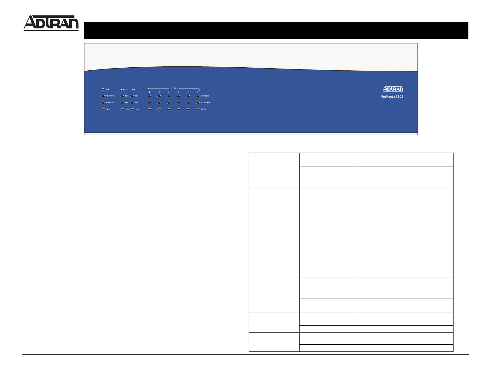
LED DESCRIPTIONS
For these LEDs… This activity… Indicates that…
Status Green (blinking) Power up process
Green (solid) Power on passed self test
Red (solid) Self test failed or boot mode code could
not be loaded
Power 1/2 Green Power supply is okay
Red Power supply failure
Off No power supply present
DBU Off No dial backup Modules installed
Green (solid) Dial backup module is ready for use
Green (blinking) The unit is in dial backup
Red (solid) Dial backup alarm condition
Yellow (solid) Unit is in test
TD/RD Green (blinking) Activity on the ethernet port
Off No activity on the ethernet port
LNK Green (solid) 10BaseT link is up
Yellow (solid) 100BaseT link is up
Red Link is down
Off Administratively down
Status
(slots 1-6) Off Empty slot or the interface is
administratively down
Green (solid) Link is up
Red (solid) Alarm condition is present on the module
Activity
(slots 1-6)
Green (blinking) Data present on the module (i.e. for the
T3 module, this indicated TD/RD data)
Off No activity on the module
Test
(slots 1-6)
Off No test running
Yellow (solid) Module in test
NETVANTA 5305 (SYSTEM) P/N 4200990L1
Quick Start Guide
Quick Start Guide, 64200990L1-13A, March 2004 Technical Support 1-888-4ADTRAN (1-888-423-8726) ©2004 ADTRAN, All Rights Reserved
For more detailed documentation, visit us online at www.adtran.com
ETHERNET PINOUT
Pin Name Description
1 TX1 Transmit Positive
2 TX2 Transmit Negative
3 RX1 Receive Positive
4, 5 — Unused
6 RX2 Receive Negative
7, 8 — Unused
CONSOLE PINOUT
Pin Name Description
1 DCD Data Carrier Detect (output)
2 RD Receive Data (output)
3 TD Transmit Data (input)
Commands
Refer to the ADTRAN Operating System (OS) Command Reference Guide
(provided on the ADTRAN OS Documentation CD) for details on configuring the
system using the Command Line Interface.
Pin Name Description
4 DTR Data Terminal Ready (input)
5 SG Signal Ground
6 DSR Data Set Ready (output)
7 RTS Request to Send (input)
8 CTS Clear to Send (output)
9 RI Ring Indicate (output)
CONSOLE PINOUT (CONTINUED)
1
2
3
REMOVE POWER CORD PRIOR
TO REMOVAL OF POWER SUPPLY
CAUTION:
85-130VAC/190-250VAC
4A/2A 50/60Hz