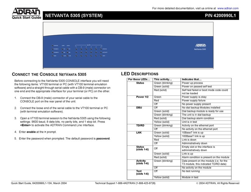
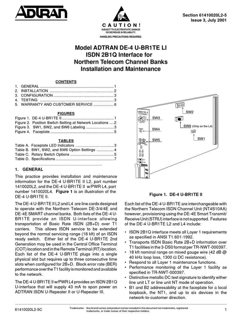
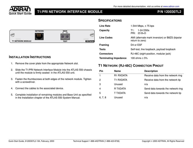
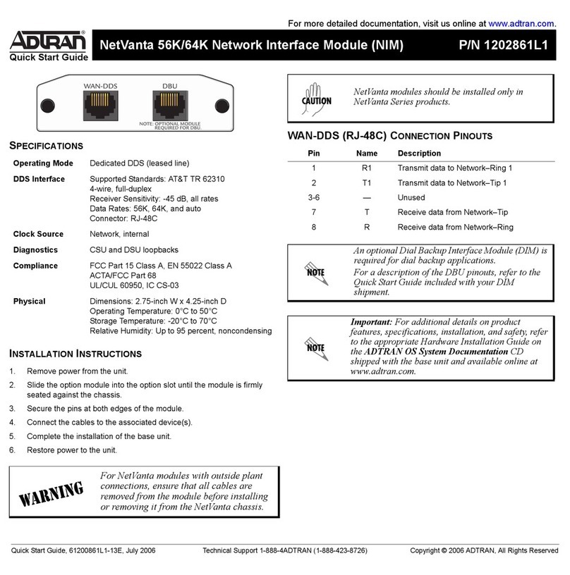
ADTRAN U-BR1TE Instruction Manual

1Section 61150277L1-5, Issue 161150277L1-5A
CONTENTS
1. GENERAL ............................................................1
2. INSTALLATION..................................................2
3. TESTING ..............................................................4
4. MAINTENANCE .................................................6
5. WARRANTY AND CUSTOMER SERVICE .....6
FIGURES
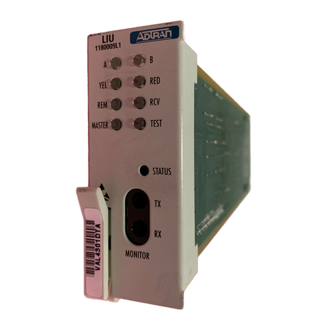
Figure 1. BR1/10 Span Power U-BR1TE ..................1
Figure 2. BR1/10 LIU and BCU ................................3
TABLES
Table 1. SW1 Functions ...........................................2
Table 2. BR1/10 BCU LED Error Information
for U-BR1TE .............................................. 3
Table 3. Connector Interface ....................................4
1. GENERAL
This practice provides installation and maintenance
procedures for the ADTRAN®BR1/10 Span Power
U-BR1TE, illustrated in Figure 1.
Revision History
This is the initial release of this document. Future
revisions will be described in this subsection.
Features
BR1/10 Span Power U-BR1TE (BR1/10),
P/N 1150277L1, features include the following:
• Supports a preferred set of options that
minimizes provisioning errors and expedites
installation.
• Features an Integrated Services Digital Network
(ISDN) 2B1Q interface that meets all Layer 1
requirements as specified in ANSI
T1.601-1992.
• Provides 18 kft nominal range on mixed gauge
wire.
• Operates in 3 DS0 format according to
TR-NWT-000397.
Section 61150277L1-5A
Issue 1, September 2000
BR1/10 Span Power U-BR1TE
ISDN 2B1Q Interface
Installation and Maintenance
Figure 1. BR1/10 Span Power U-BR1TE
Trademarks: Any brand names and product names included in this document are trademarks,
registered trademarks, or trade names of their respective holders.
• Features performance monitoring of the Layer 1
facilities as specified in TR-NWT-000397 and
TR-TSY-000829.
• Responds to B1, B2, and 2B+D loopbacks
through the embedded operations channel (eoc).
• Operates with BR1/10 Line Interface Unit
(LIU) and Bank Controller Unit (BCU) to
provide local access to test each channel unit.
General Description
The BR1/10 is a line card that plugs into a single
channel slot of an ADTRAN BR1/10 channnel bank,
and provides the interface between the Digital
Sub-scriber Line (DSL) and the E1 carrier facility.
The BR1/10 operates in the TR-NWT-000397 3-DS0
mode allowing up to ten individual BR1TE cards for
each E1 carrier facility.
1
Status
LED
SW1

2 Section 61150277L1-5, Issue 1 61150277L1-5A
Options for the BR1/10 are selected with the
3-position DIP switch (SW1) on the U-BR1TE circuit
board. The STATUS LED provides synchronization
information for local craft personnel. See Figure 1
and Table 1.
2. INSTALLATION
After unpacking the unit, inspect it for damage. If
damage is noted, file a claim with the carrier, then
contact ADTRAN. See Warranty and Customer
Service.
NOTE
The BR1/10 operates in conjunction with the
channel bank’s LIU and BCU. The I&M
Practices for those units: 61150279L2-5 and
61150280L2-5, should be available for
reference.
U-BR1TE Status LED
The front panel status LED provides the following
information:
• OFF - No power
• Red - Units not synchronized
• Green - Units synchronized
• Red/Green Flashing - A 3-second flashing
indicates selection by the LIU channel selection
switch.
The BR1/10 inserts in any of the BR1/10 chassis slots
labeled 1 through 10. Insert the unit into the back-
plane connector until firmly seated. At this point the
STATUS LED on the U-BR1TE should illuminate
Red indicating that synchronization has not been
achieved for either the ISDN U-Interface or the E1
interface. When both interfaces are synchronized, the
STATUS LED will change to Green. If the LED stays
Red, check the BCU LEDs to determine the error
type.
BCU Status LEDs
The BR1/10 channel bank selection and status is
obtained by using the LIU and BCU common units.
See Figure 2.
Additional status is displayed by the bottom six BCU
LEDs when the subject unit is selected with the LIU's
DSL Channel Selection switch. When a BR1/10 is
selected by the LIU rotary switch, the BR1/10 Status
LED will flash Red/Green indicating that the unit has
been selected and is establishing communication with
the BCU. After about 3 seconds the LED returns to
the current synchronization status.
Following selection, status information for the
selected unit is provided by the six BCU LEDs,
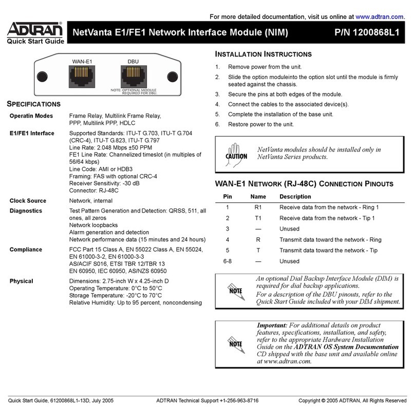
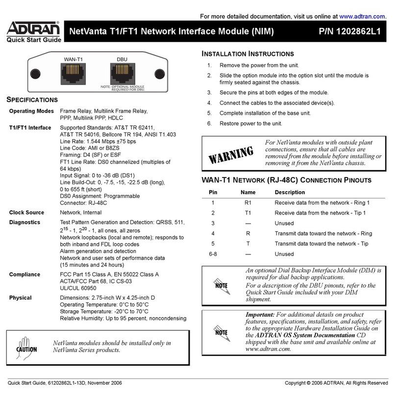
shown here:
LP-SYNC OOCRC
CR-SYNC OOCRC
DS0-LB OOACT
A summary of error information is provided in
Table 2. For more information, see BCU Installation
and Maintenance Practice, number 61150280L2-5.
C A U T I O N !
SUBJECT TO ELECTROSTATIC DAMAGE
OR DECREASE IN RELIABILITY.
HANDLING PRECAUTIONS REQUIRED.
Table 1. SW1 Functions
hctiwSsutatSnoitpircseD
1-1WSNO
FFO
senotpu-ekawcidoireP-edomTLUL .delbasid senotpu-ekawcidoireP-edomTNUL .delbane ebdluohssenotpu-ekawcidoireP detacolsi01/1RBehtnehwdelbane mednaTani,hctiwSottnecajdA nehwro,noitarugifnockniSeciffO seriuqertahtecivedaottnecajda egdirbweNasahcussenotpu-ekaw .hctiws
2-1WSNOFFO .delbanerewopnapS .delbasidrewopnapS
3-1WSNOFFO .edomNDSI .edomenildesaeL

3Section 61150277L1-5, Issue 161150277L1-5A
Figure 2. BR1/10 LIU and BCU
1150279L2
E1 LIU
ADR1
IN
OUT
T
E
S
T
ADR2
ADR3
ADR4
T
E
S
T
ADR6
AD
R5
4
10 1
2
3
5
6
7
9
8
G.703
ALM
OFF
LOC
B1
LB ON
REMOTE
B2
LOC
LOOP
EXT
HDB3
75
Ω
E1-LOC
LP-SYNC
CR-SYNC
DSO-LB
AMI
120
Ω
RMT
CRC
CRC
ACT
1150280L2
E1 BCU
TEST
Recessed Push
Button
Channel Selection
Loopback Address
DB-9 Connector
BCU Test Switch
Table 2. BR1/10 BCU LED Error Information for U-BR1TE
DELnoitcnuFsutatSnotpircseD
CNYS-PL )der( ecafretniPD-SD noitazinorhcnys NO
FFO
romaertspuetairporppA-ecafretni-Ueriw-2nonoitazinorhcnysoN NDSIro,ET1RB-UmednaT,retaeper-U,1TN(tinuNDSImaertsnwod .noitcnuflamLSD,rO.dellatsni/gnidnopserton)hctiws .dezinorhcnysstinU
CNYSRC )der( ecafretnireirraC noitazinorhcnys NO
FFO
-lufsseccusnutnemelekrowtenNDSIrehtonaotreirrac1EssorcagnimarF .knablennahcetomertadellatsni/gnidnopsertontinulennahcetaicossA .noitcnuflamytilicafreirrac1E,rO .dezinorhcnysstinU
*CRCPL )der( PD-SDD ecafretni srorreCRC
NO
FFO
roLSDnomelborpesioN-ecafretni-Ueriw-2morfsrorreCRCgnivieceR .tnemelekrowtenNDSIrehto .poolmorfsrorreoN
*CRCRC )der( ecafretnireirraC srorreCRC NO
FFO
nonoitpoSBZfohctamsiM-reirrac1EmorfsrorreCRCgnivieceR .ytilicafreirrac1Enororregnimit,rO.tinuET1RBdetaicossa .reirracmorfsrorreCRCoN
BL-0SD )wolley( sutatSkcabpooLNOgnihsalF
FFO
.kcabpoolgnitaitinI .kcabpool1Brofdnoces/1 .kcabpool2Brofdnoces/2 .evitcanikcabpooL
TCA )neerg( tiBnoitavitcANOgnihsalF FFO
.lufsseccusstinuetomerdnalacolneewtebstibnoitavitcafoegnahcxE .ylnonoitceridenonitnestibnoitavitcA .tnestonstibnoitavitcA
otrefeR* gnirotinoMecnamrofrePlacoL noitcesbus.noitacidniDELlanoitiddarof

4 Section 61150277L1-5, Issue 1 61150277L1-5A
Connections
Table 3 shows the wiring interconnects to the
backplane amphenol connector for the 2-wire
U-Interface. All other input and output to the BR1/10
are made through the backplane.
3. TESTING
The BR1/10 responds to standard eoc testing
including B1, B2, and 2B+D loopbacks. These eoc
commands are sent from an upstream device such as
the ISDN switch, another U-BR1TE, or an ISDN test
set. This loopback capability provides for remote
testing.
DS0 TESTING
DS0 local test access allows local craft personnel to
assist in circuit turn-up, or sectionalization of trouble
or equipment malfunction when remote testing is not
available or convenient.
The BR1/10 BCU and LIU provide the required
network access for testing downstream ISDN devices,
inserting a test pattern to either the carrier or loop
interface, performing a local bilateral loopback, and
performing local performance monitoring of the ISDN
circuit.
When DS0 is selected on the BR1/10 BCU, local test
access is afforded to each of the installed BR1/10
BR1TE channel units in both the downstream and
upstream directions. Bantam jacks for DS0 logic
access, 8 and 64 kHz clock reference, selection of the
desired channel unit (1-10), and the desired test are
provided by the BR1/10 LIU. When the 10-position
rotary switch is used to select a BR1TE channel unit,
the Status LED on the BR1TE channel unit will flash
Red and Green for approximately 3 seconds before
returning to the current status display.
Loopback Test (ADR1-ADR6, NT1)
Loopbacks in the network-to-customer direction can
be initiated from either the ISDN switch or the BR1/
10 LIU. The downstream direction is automatically
selected based on the card position in the network. To
initiate a loopback, perform the following steps:
1.Insert the TX and RX bantam plugs of the DS0
digital test set into the bantam jack of the LIU.
Connect the clock input to the DS0 digital test
set DB-9 connector on the LIU. Configure the
test set for Near Logic and 64 kbps.
2.Select the desired BR1TE channel unit using
the DSL rotary switch on the LIU. The selected
BR1TE channel card status LED will flash
Green and Red for approximately 3 seconds
when selected.
3.Select the desired loopback address on the LIU
(ADR1-ADR6, or NT1).
4.Select the desired bearer channel using the B1/
B2 DIP switch on the BCU.
5.Depress the BCU’s recessed TEST pushbutton
to initiate the loopback test. The DS0-LB status
LED will light Yellow when the loopback is
established to the selected address. If the
selected address does not respond, the DS0-LB
LED will remain out. Observe the DS0 digital
set for bit errors.
noitisoPlennahCniPdaeL
172
2R
T
292
4R
T
313
6R
T
433
8R
T
55301 R
T
67321 R
T
79341 R
T
81461 R
T
93481 R
T
015402 R
T
Table 3. Connector Interface

5Section 61150277L1-5, Issue 161150277L1-5A
6.Test the other B channel or additional network
ISDN devices by changing to another test (steps
3 and 4). It is not necessary to exit the test
mode to select a new test. If a new BR1TE
channel unit is selected, all DS0 tests will be
terminated.
7.To terminate the loopback, depress the TEST
pushbutton, or remove the transmit bantam
plug. Upon deactivation of the test, the
DS0-LB LED will go out.
Point-to-Point Test (CRTX, LPTX)
A point-to-point (straightaway) test can be performed
on either the U-interface (LPTX) or the E1 carrier
interface (CRTX).
To initiate a point-to-point test using a DS0 digital test
set, perform the following steps:
1.Insert the TX and RX bantam plugs of the DS0
digital test set into the bantam jack on the LIU.
Connect the clock input to the DS0 digital test
set DB-9 connector on the LIU. Configure the
test set for Near Logic and 64 kbps.
2.Select the desired BR1TE channel unit using
the DSL rotary switch on the LIU. The selected
BR1TE channel card status LED will flash
Green and Red for approximately 3 seconds
when selected.
3.Select the desired test direction, LPTX or
CRTX, on the LIU.
4.Select the desired bearer channel using B1/B2
DIP switch on the BCU.
5.Depress the recessed TEST pushbutton on the
BCU to initiate the test.
6.If the far end unit is a BR1/10 BR1TE channel
unit, perform steps 1 through 4 choosing the
same front panel switch setting. Ensure both
test sets are configured for the same test pattern
(511, 2047).
7.Observe the DS0 digital test set for bit errors.
8.To deactivate the loopback, depress the TEST
pushbutton or remove the transmit bantam
plug. Upon deactivation of the test the
DS0-LB LED will go out.
Local Loopback (LPBK)
A bilateral loopback can be initiated for any of the
BR1/10 BR1TE channel units for either bearer
channel. Since a local test pattern source is not
required for this test, it can be performed without
additional test equipment. To initiate a local
loopback, perform the following steps:
1. Select the desired BR1TE channel unit using
the DSL rotary switch on the LIU. The selected
BR1TE channel card status LED will flash
Green and Red for approximately 3 seconds
when selected.
2.Select the LPBK using the 10-position rotary
switch.
3.Select the desired bearer channel using the B1/
B2 DIP switch on the BCU.
4.Depress the recessed TEST pushbutton to
initiate the test. The DS0-LB LED will flash
once per second for a B1 loopback, twice per
second for a B2 loopback.
5.To deactivate the loopback, depress the TEST
pushbutton. Upon deactivation of the test, the
DS0-LB LED will go out.
Local Performance Monitoring
Performance monitoring of the local E1 carrier system
and the 2-wire U-interface of the ISDN data can be
performed from the front panel without interruption of
service to the customer. For this test, bearer channel
selection is not applicable and a test pattern source is
not required. To initiate local performance monitoring,
perform the following steps:
NOTE
LED indication in response to the TEST
pushbuttonasexplainedhereisinadditionto
that explained in Table 2.
1.Ensure a bantam plug is NOT installed in the
front panel TX bantam jack on the BR1/10
LIU.
2.Select the desired BR1TE channel unit using
the DSL rotary switch on the LIU. The selected
BR1TE channel card status LED will flash
Green and Red for approximately 3 seconds
when selected.
3.Select ADR1 on the LIU.
4.Depress the recessed TEST pushbutton to
initiate the test.
6 Section 61150277L1-5, Issue 1 61150277L1-5A
5.The total number of crc errors is simultaneously
displayed by the LP and CR CRC status LEDs.
The LEDs will flash when 6 to 19 crc errors
have been received and will illuminate solid
when 20 or more crc errors have beenreceived.
6.To exit local performance monitoring, depress
the TEST pushbutton.
4. MAINTENANCE
The BR1/10 Span Power U-BR1TE does not require
maintenance for normal operation.
ADTRAN does not recommend that repairs be
performed in the field. Repair services are obtained
by returning the defective unit to ADTRAN.
5. WARRANTY AND CUSTOMER SERVICE
ADTRAN will replace or repair this product within 5
years from the date of shipment if it does not meet its
published specifications or fails while in service (see
ADTRAN Carrier Networks Equipment Warranty,
Repair, and Return Policy and Procedure, document
60000087-10A).
Contact Customer And Product Service (CAPS) prior
to returning equipment to ADTRAN.
For service, CAPS requests, or further information,
contact one of the following numbers:
ADTRAN, Inc.
Attention: International Department
901 Explorer Boulevard
Huntsville, Alabama 3580
USA
www.adtran.com
Asia Pacific - Hong Kong
852 2824-8283 voice
852 2824-8928 fax
Canada - Ontario
1 416 290-0585 voice
1 416 296-1259 fax
Canada - Quebec
1 877 923-8726 toll free
1 514 940-2888 voice
1 514 940-2890 fax
Canada - Other Provinces
1 877 923-8726 toll free
Europe - Zurich, Switzerland
41 1 880 27 77 voice
41 1 880 27 78 fax
Latin America
1 954 746-5355 voice
1 954 746-7540 fax
Mexico/Caribbean
1 954 577-0357 voice
1 954 577-0358 fax
U. S. Headquarters
1 256 963-2500 voice
1 256 963-6300 fax
1 256 963-8200 fax back
Other manuals for U-BR1TE
6
Table of contents
Other ADTRAN Recording Equipment manuals

ADTRAN
ADTRAN DE-4 U-BR1TE LI Instruction Manual

ADTRAN
ADTRAN NetVanta 5305 User manual

ADTRAN
ADTRAN RJ-48C User manual

ADTRAN
ADTRAN SHDSL T1 User manual

ADTRAN
ADTRAN Total Access 1500 Instruction Manual

ADTRAN
ADTRAN NT1 400 User manual

ADTRAN
ADTRAN T1/PRI User manual

ADTRAN
ADTRAN 9004 U-BR1TE II ISDN 2B1Q Maintenance and service guide

ADTRAN
ADTRAN DS3 NIU3 Instruction Manual

ADTRAN
ADTRAN Network Interface Module T1/FT1 User manual