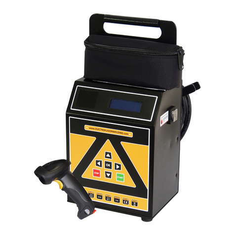
Advance acoustic ATS 180 User manual

ATS180 - Operator Manual
Operating Controls
ATS 180
© 2019. Advance Welding 1
Operating Controls ........................................................................................................................
Safety Notes .....................................................................................................................................
Product Specication ...................................................................................................................
Intended Use ....................................................................................................................................
Introduction ......................................................................................................................................
Delivered Items ................................................................................................................................
Electrical Safety ................................................................................................................................
Using the Equipment .....................................................................................................................
Data Log Memory ............................................................................................................................
Manual Welding .............................................................................................................................
Fusamatic Welding .......................................................................................................................
Bar Code Welding .........................................................................................................................
Fusion Operator Badge ..............................................................................................................
GPS Location .................................................................................................................................
Extreme Low Temperature Operation .................................................................................
Downloading the Weld Memory .............................................................................................
Upgrading the Operating Software .......................................................................................
Set Up Options ..............................................................................................................................
Information .....................................................................................................................................
Fault Finding ...................................................................................................................................
Maintenance ..................................................................................................................................
Disposal ............................................................................................................................................
Calibration and Warranty ...........................................................................................................
Declaration of Conformity ........................................................................................................
Service and Repair.........................................................................................................................
Quick Start Guide ..........................................................................................................................
ATS 180
Shoulder Bag, Frame and
Combination Unit Models
Operating manual

ATS180 - Operator Manual
ATS 180
© 2019. Advance Welding 2
Index .................................................................................................................................................
Operating Controls ....................................................................................................................
Safety Notes ..................................................................................................................................
Product Specication ...............................................................................................................
Intended Use ................................................................................................................................
Introduction ...................................................................................................................................
Delivered Items .............................................................................................................................
Electrical Safety.............................................................................................................................
Duty Cycle .......................................................................................................................................
Using the Equipment .................................................................................................................
Data Entry .......................................................................................................................................
Welding ............................................................................................................................................
Options Menu ...............................................................................................................................
Maintenance ..................................................................................................................................
Fault Finding ...................................................................................................................................
Disposal ...........................................................................................................................................
Calibration and Warranty ...........................................................................................................
Declaration of Conformity ........................................................................................................
Service and Repair .......................................................................................................................
Index
2
3
4
5
6
6
6
7
8
9
10
12
15
22
23
27
28
30
31

ATS180 - Operator Manual
ATS 180
© 2019. Advance Welding 3
1. Supply Cable
2. Temperature Sensor
3. Protective Bag
4. On/O Switch
5. Cooling Fan
6. Display
7. Buttons
8. Welding Cable
9. Bar code scanner reader
1. Welding Cable (can be provided with optional right angle plug)
2. USB Memory Drive
3. Bar Code Scanner (Optional)
4. Bar Code Pen (Standard)
5. USB Socket
6. Welding Cable Socket
7. Protective Lid
8. Display
9. Buttons
10. Protective Frame
11. Ratings Plate
12. Supply Cable
Operating Controls
8. Welding Cable
9. Bar Code Scanner Reader 6. Display
3. Protective Bag
5. Cooling Fan
(On side of case)
2. Temperature Sensor
(On side of case)
1. Supply Cable
7. Buttons
4. On/O Switch
(On side of case)

ATS180 - Operator Manual
ATS 180
© 2019. Advance Welding 4
• RISK OF EXPLOSION! This welding unit must not be used in a gaseous
atmosphere.
• RISK OF ELECTRIC SHOCK! Do not open. No user serviceable parts
inside.
• Before using, always visually inspect the unit to see that the cables and
connectors are not worn or damaged. Replace the damaged part before
welding.
• Switch o and remove the plug from the mains before adjusting, cleaning, or
if the cables are entangled and before leaving the equipment unattended for
any period.
• To avoid damaging the unit, do not interrupt the supply voltage or disconnect
the welding cable, while the unit is welding a tting.
• Do not lift or pull the equipment by its cables.
• Do not disconnect the welding cables by pulling on them, always pull o the
connectors from the tting.
• Do not start a weld without the pipe correctly inserted into the tting.
• Do not touch the tting while welding.
• Do not weld in the rain or leave the equipment outdoors whilst it is raining.
• Weld only in daylight or in good articial light.
• The operator is responsible for accidents or hazards occurring to other people
or their property while using this equipment. Keep the work area safe!
• Keep bystanders a safe distance away from the machine while welding.
• Never allow people unfamiliar with these instructions to use the welding unit.
Safety Notes

ATS180 - Operator Manual
ATS 180
© 2019. Advance Welding 5
Product Specication
Input Power Connections
for this model:
• 110V version
• 120V version
• 230V version
Input plug for your region or
country are available
Contact us for more information
Bespoke OEM
As a bespoke OEM Original Manufacturer we can
produce this product as an OEM to suit your business
Contact us to discuss your requirements
Specication details - ATS 180
Operating Modes Manual, Barcode
Welding Voltage 39.5V (8 to 48V)
Welding Current 1-50A
Welding Time 1-1500 seconds
Supply Voltage
115 ± 15% 110V
(40-60Hz)
230 ± 15% 230V
(40-60Hz)
Supply Current 1-25A (115V)
1-12A (230V)
Supply Power 3000 W
Weight 11 kg
12 kg
Size 30 x 21 x 26cm
33 x 25 x 34cm
Operating Temp. -15ºC to +50ºC
Advance Welding has a policy of continuously improving product design, and as such reserve the
right to change specication of its products without prior notice and with impunity.

ATS180 - Operator Manual
ATS 180
© 2019. Advance Welding 6
This equipment is intended to weld constant voltage electrofusion ttings suitable for low,
medium and high pressure pipe work systems.
This welding unit has been designed to comply with the International Organization for
Standardization standard ISO12176-2:2000 “Plastic pipes and ttings, equipment for fusion
jointing polyethylene systems , part 2, electrofusion”.
This manual gives instructions on the correct assembly and safe use of your welding unit. It
is important that you read these instructions carefully, and keep these instructions for the
life of the unit.
This manual does not detail the specic welding procedure for the ttings: scraping,
clamping and assembly of joints. For this information you must contact the manufacturer of
the ttings.
Carefully remove the welding unit from its packaging and check that you have the following
items:
• Welding unit.
• Bar code reading scanner
• Operating Manual
• USB Memory drive
• Protective carrying bag.
When parts are missing or damaged, please contact your dealer.
Intended Use
Introduction
Delivered Items

ATS180 - Operator Manual
ATS 180
© 2019. Advance Welding 7
Electrical Safety
WARNING! Switch o and remove the plug from the mains before adjusting,
cleaning or if the cable is cut, damaged or entangled.
This welding unit is Class 1 and requires an earthed (grounded) connection. An earth
spike must be used with generators.
This unit is supplied in either 110 volt or 230 volt operation. Check the rating plate
on the side of the unit for the correct supply voltage.
The power source must be capable of providing 3500 Watts.
Extension cables should only be used if they comply with the H07RNF harmonized
standard. They must be tted with connectors to the BS EN 60309-2 standard. All
cables must be unwound from the reel to stop inductive heating eects. The cable
dimensions should be as follows:
It is recommended for increased electrical safety to use a Residual Current Device
(RCD) with a tripping current of not more than 30 mA. Always check your RCD every
time you use it.
The supply cable must be inspected for signs of damage before each use and the
equipment may only be used if in perfect condition. Damaged cables must be
replaced by an approved service agent.
This equipment is classied as “Portable for use on industrial applications”, and
must undergo a formal electrical safety check (Portable Appliance Test) as per local
regulations.
110V Volt operation
Up to 63mm diameter
2.5mm2 cable = 30m
Up to 180mm diameter
2.5mm2 cable = 20m
230 Volt operation
Up to 63mm diameter
1.5mm2 cable = 40m
Up to 180mm diameter
1.5mm2 cable = 25m

ATS180 - Operator Manual
ATS 180
© 2019. Advance Welding 8
The equipment is designed for everyday use on connection size ttings up to 110mm
diameter. It can also weld ttings up to 200mm diameter (8”) but with a reduced duty
cycle.
Larger diameter ttings generate a lot of heat within the equipment and it must be
allowed to cool down between fusion cycles. The equipment uses fan cooling and it is
preferable to have the equipment switched on with the fan running to accelerate the
cooling.
For larger diameter ttings (above 110mm) it is recommended to have up to one hour
cooling time between fusion cycles. Failure to allow the equipment to cool properly
could seriously damage it.
If the equipment has not cooled correctly, then it may not complete the next fusion
cycle correctly. Advance welding accepts no responsibility if the operator fails to
adhere to the correct cooling cycle.
Duty Cycle

ATS180 - Operator Manual
ATS 180
© 2019. Advance Welding 9
Prepare and clamp the pipe and ttings inline with the manufacturers
recommendations. Connect the supply cable to the correct supply voltage and switch
the unit on.
The screen will show the model number and software version. It will also show the
current date and the calibration due date.
After a short pause the owner details will be shown.
The display will now show the “Connect Fitting” screen.
Connect the welding cable to the tting to begin the welding process.
Press the STOP button to enter the data logging menu.
Press the OK button to enter the options menu.
The supply voltage and frequency are shown. This allows the operator to check the
quality of the power supply before welding starts.
Using the equipment
A D V A N C E W E L D I N G
A T S 1 8 0 E X T R A A . 1 . 0 2
C A L D U E : 0 9 / 1 0 / 2 0 1 4
1 0 : 3 1 1 9 / 1 0 / 2 0 1 5
P R O P E R T Y O F :
A D V A N C E W E L D I N G
TEL : 0844 8807748
FAX : 0870 7526139
C O N N E C T F I T T I N G
S T O P : D A T A L O G I N F O
O K : M E N U
S U P P L Y : 2 4 0 V 5 0 H Z

ATS180 - Operator Manual
ATS 180
© 2019. Advance Welding 10
Letters and numbers are entered using the arrow buttons. Using the up and down
arrows will scroll through the list of A to Z and 1 to 9. When the correct letter has been
chosen, pressing the right arrow button will move to the next position. If a mistake has
been made the left arrow button can be used to backspace.
For example, in the following screen:
To enter 40 seconds…
Press the up arrow button four times until the 4 is shown.
Press the right arrow button to move to the next position.
Press the down arrow button once until the 0 is shown.
Press the OK button to accept 40.
Data Entry
M A N U A L W E L D I N G
T I M E : _ _ _ _ S
V O L T S : 3 9 . 5 V
O K

ATS180 - Operator Manual
ATS 180
© 2019. Advance Welding 11
G F S A D D L E + 2 2 C
1 2 5 M M 8 0 S 4 0 . 0 V
S C R A P E D & C L A M P E D ?
P R E S S S T A R T
F U S I O N B A R C O D E
R E A D C O D E
N U M B E R S M A N U A L V / T
Welding modes:
Bar Code Yes
Manual Yes
Data Logging Yes
Connect the welding cable to the tting and the screen will show
Read the bar code on the tting. If the code is read correctly then a message will be
displayed saying “Read OK”. Next, the resistance of the tting will be measured and
checked to the bar code data. If they match the message “Fitting Resistance Veried
OK” will be shown. This is to make sure the correct bar code for the correct tting is
read. The display will now show
Conrm that the pipe and tting have been correctly prepared and start the welding by
pressing the START button.
During the welding, the following screen will be displayed:
The elapsed time will count up from zero to the set weld time
C O N N E C T F I T T I N G
S T O P : D A T A L O G I N F O
O K : M E N U
S U P P L Y : 2 4 0 V 5 0 H Z
Welding
W E L D N U M B E R : 2 3 5
W E L D T I M E : 8 0 S
E L A P S E D : 2 2 S
4 0 . 0 1 V 5 . 1 4 A

ATS180 - Operator Manual
ATS 180
© 2019. Advance Welding 12
The cooling time will now count up. This is to help the operator know when the weld
ended and will continue to count up until the lead is disconnected from the tting.
Disconnect the lead and the unit will reset back to the “Connect Fitting” message.
NUMBER ENTRY
If the bar code pen does not work or the bar code label on the tting has been
damaged, then the barcode numbers can be manually entered. On the “Read Code”
screen, press the UP arrow button. The following screen will be displayed:
Many bar code labels show the 24 numbers underneath the bar code stripes. Read
these from the label and enter them. When all numbers have been entered, press the
OK button.
The display will now show
Conrm that the pipe and tting have been correctly prepared and start the welding
by pressing the START button.
The welding voltage and current will be displayed to allow the operator to conrm the
welding process is correct.
When the weld is complete, the following screen will be displayed:
C O O L I N G T I M E : 0 4 : 5 1
D I S C O N N E C T L E A D T O
C O M P L E T E W E L D 2 3 5
F U S I O N D I G I T S
____________________
____
O K
G F S A D D L E + 2 2 C
1 2 5 M M 8 0 S 4 0 . 0 V
S C R A P E D & C L A M P E D ?
P R E S S S T A R T

ATS180 - Operator Manual
ATS 180
© 2019. Advance Welding 13
MANUAL ENTRY
If the bar code pen does not work or the bar code label on the tting has been
damaged and there are no numbers shown on the label, then the time and voltage
can be entered manually. On the “Read Code” screen, press the DOWN arrow button.
The following screen will be displayed:
Enter the welding time and press the OK button.
The welding voltage can now be entered. This will default to 39.5 volts. Use the up and
down arrows to select the required voltage and press the OK button to select.
The screen will display the following:
Conrm that the pipe and tting have been correctly prepared and start the welding
by pressing the START button.
M A N U A L W E L D I N G
T I M E : _ _ _ _ S
V O L T S : 3 9 . 5 V
O K
M A N U A L W E L D I N G + 2 0 C
8 0 S 3 9 . 5 V
S C R A P E D & C L A M P E D ?
P R E S S S T A R T

ATS180 - Operator Manual
ATS 180
© 2019. Advance Welding 14
DATA LOGGING
If data logging information is required, on the “Connect Fitting Screen” press the
STOP button. The screen will show:
Enter the Operator Name press the OK button. The screen will now show:
Enter the Location and press the OK button. The screen will now show:
Enter the Job Reference and press the OK button. The screen will now show:
Continue with the welding process by connecting the welding cable to the tting.
C H A N G E O P E R A T O R N A M E
__________________
O K
C H A N G E L O C A T I O N
__________________
O K
C H A N G E J O B R E F E R E N C E
__________________
O K
C O N N E C T F I T T I N G
S T O P : D A T A L O G I N F O
O K : M E N U
S U P P L Y : 2 4 0 V 5 0 H Z

ATS180 - Operator Manual
ATS 180
© 2019. Advance Welding 15
Options Menu
When the display shows the “Connect Fitting” message, pressing the OK button will
enter the options menu.
Press OK and the display will show:
Use the up and down arrows to scroll through the options. When the required option
is shown press the left or right arrow to select it.
For additional security, some options require a Supervisor or Workshop password to
access them. This stops the operator adjusting features without permission. When
asked for a password, the following screen will be shown:
Enter the Supervisor Password. Use the up and down arrows to scroll through A to Z
and then use the left and right arrows to move between positions. When the correct
password has been entered press the OK button.
The Supervisor and Workshop passwords are available on request.
Important! Not all options are available on all models of ATS180.
C O N N E C T F I T T I N G
S T O P : D A T A L O G I N F O
O K : M E N U
S U P P L Y : 2 4 0 V 5 0 H Z
W E L D I N G
D A T A D O W N L O A D
S Y S T E M O P T I O N S
S U P E R V I S O R P A S S W O R D
_ _ _ _ O K = C O N T I N U E
S T O P = C A N C E L

ATS180 - Operator Manual
ATS 180
© 2019. Advance Welding 16
D A T A D O W N L O A D
= V I E W L A S T W E L D
O K = C O N T I N U E
S T O P = C A N C E L
This will allow the stored data log memory to be downloaded to a USB memory drive.
To view the details of the last weld on the screen, press the up arrow. All stored information
will be shown.
To download the data, unplug the bar code reading pen from the USB socket and connect
a USB memory drive. Follow the instructions shown on the screen. The data will be
downloaded.
This will allow the clock to be set.
This will allow the date to be set.
Data Download Operator
Set Time Operator
Set Date Supervisor
C L O C K 2 4 H R 1 5 : 1 0
O K
D A T E D D M M Y Y 1 9 / 1 0 / 0 9
O K
E N E N G L I S H
E S E S P A N O L
This will allow dierent display languages to be selected. Use the up and down arrow
buttons to scroll through the available languages. When the required language is shown,
press the left or right arrow button to select it.
Change Language Supervisor

ATS180 - Operator Manual
ATS 180
© 2019. Advance Welding 17
This will change the format of the date and temperature into UK Metric format. The
date will be set to dd/mm/yy and the temperature to Celsius.
This will change the format of the date and temperature into US Imperial format. The
date will be set to mm/dd/yy and the temperature to Fahrenheit.
This will allow the operating software to be updated. After the software has prepared
for the update the screen will show:
The software should be copied onto the USB memory drive and it should be
inserted into the USB socket on the unit. Press the right arrow button and follow the
instructions to update the software. When complete, a message showing “Success!”
will be displayed. Switch the power o and on to restart the welding unit with the new
software.
UK Data & Celsius Operator
US Date & Fahrenheit Operator
Software Update Operator
U K D A T E / T E M P M O D E
U S D A T E / T E M P M O D E
P R E P A R I N G F O R U P D A T E
P L E A S E W A I T . . .
C O N N E C T M E M O R Y S T I C K
W I T H S O F T W A R E U P D A T E
T O U S B P O R T
= C O N T I N U E

ATS180 - Operator Manual
ATS 180
© 2019. Advance Welding 18
This will display the warranty information for the unit, when it was sold and what the weld counter was.
This will show basic information about the last calibration, then the weld counters will be shown:
This will show the date the unit was rst used from new:
Warranty Information Operator
First Use Date Operator
Display Basic Calibration Information Operator
P U R C H A S E I N F O R M A T I O N
S O L D O N : 2 1 / 0 9 / 0 9
W E L D C O U N T : 0 0 0 0 0 4
O K = C O N T I N U E
E C U F I R S T U S E D O N :
2 1 / 0 9 / 2 0 0 9
A W P A R T A W 1 1 - 2 3 1 0
S E R I A L A T S 2 5 0 - 0 0 0 1
C A L D A T E 0 9 / 1 0 / 2 0 0 9
P E R I O D W 1 2 M O N T H S
This will show the full calibration information. Use the right arrow button to scroll through the
calibration information. This will show all of the values entered when the unit was last calibrated.
Display Full Calibration Information Operator
W E L D C O U N T E R
C U R R E N T C O U N T 0 0 0 2 7 8
L A S T C A L 0 0 0 2 0 5
S I N C E C A L 0 0 0 0 7 3
C A L I B R A T I O N D A T A . . .
@1 6 : 0 3 1 9 / 1 0 / 0 9
W E L D C O U N T : 0 0 0 2 7 8
W E L D S @C A L : 0 0 0 2 0 5

ATS180 - Operator Manual
ATS 180
© 2019. Advance Welding 19
This will display the resistance of the tting connected to the welding cable. This option can be
used for fault nding, to make sure the welding unit is measuring the tting resistance correctly.
This can be used to erase the data log information after it has been downloaded to a USB
memory drive. Press the left arrow to erase the log or the right arrow to cancel.
Display Ohm Meter Operator
Erase Data Log Supervisor
F I T T I N G R E S I S T A N C E :
0 0 8 . 0 4 4 O H M S
P R E S S S T O P T O E X I T
E R A S E L O G ?
= N O
= Y E S
This will encrypt the data download into a format that can not be altered. This gives extra
security to the downloaded data. The information can not be adjusted by the supervisor. A
“Download Manager” program is available to decrypt this format.
This will format the data download as plain text. The downloaded data le will have the
format “XLS” to allow Microsoft Excel to open the information as a spreadsheet.
Erase Data Log Supervisor
Plain Data Download Supervisor
E N C R Y P T E D
N O T E N C R Y P T E D

ATS180 - Operator Manual
ATS 180
© 2019. Advance Welding 20
In bar code welding, the actual resistance of the tting is matched against the information
in the bar code label. This option will force the checking of the tting resistance. If there is a
dierence, the weld will not be allowed to continue.
Barcode Ohms Required Supervisor
Barcode Ohms Warn Supervisor
B A R C O D E O H M S C H E C K
O V E R R I D E D I S A B L E D
B A R C O D E O H M S C H E C K
O V E R R I D E E N A B L E D
In bar code welding, the actual resistance of the tting is matched against the information
in the bar code label. With this option set, if the resistance of the tting does not match the
information in the bar code, a warning message will be displayed. The operator can accept
this message and continue welding.
This option allows an authorised service agent to calibrate the unit
This option allows an authorised service agent to change the owner details.
Full Calibration Workshop
Change Owner Information Workshop
C A L I B R A T I O N ?
= Y E S
= N O
C U S T O M E R D E T A I L S
= A D V A N C E W E L D I N G _ _ _
=TEL 0870 6093257__
=FAX 0870 7526139__
Table of contents
Other Advance acoustic Welding System manuals
Popular Welding System manuals by other brands

Thermal Arc
Thermal Arc POWERMASTER 350P Service manual

EWM
EWM Pico 350 cel puls pws MMA operating instructions

Lincoln Electric
Lincoln Electric ARC TRACKER K3019-1 Operator's manual

EINHELL
EINHELL BT-GW 190 D Original operating instructions

GYS
GYS EASYCUT 30 FV manual

Xcel-Arc
Xcel-Arc VIPER SYNERGIC MIG165 operating manual